Publisher’s version / Version de l'éditeur:
Journal of the Soil Mechanics and Foundations Division, 88, SM2, pp. 1-17,
1962-07-01
READ THESE TERMS AND CONDITIONS CAREFULLY BEFORE USING THIS WEBSITE. https://nrc-publications.canada.ca/eng/copyright
Vous avez des questions? Nous pouvons vous aider. Pour communiquer directement avec un auteur, consultez la première page de la revue dans laquelle son article a été publié afin de trouver ses coordonnées. Si vous n’arrivez pas à les repérer, communiquez avec nous à [email protected].
Questions? Contact the NRC Publications Archive team at
[email protected]. If you wish to email the authors directly, please see the first page of the publication for their contact information.
NRC Publications Archive
Archives des publications du CNRC
This publication could be one of several versions: author’s original, accepted manuscript or the publisher’s version. / La version de cette publication peut être l’une des suivantes : la version prépublication de l’auteur, la version acceptée du manuscrit ou la version de l’éditeur.
Access and use of this website and the material on it are subject to the Terms and Conditions set forth at
Experiences with ground water on construction
Legget, R. F.
https://publications-cnrc.canada.ca/fra/droits
L’accès à ce site Web et l’utilisation de son contenu sont assujettis aux conditions présentées dans le site
LISEZ CES CONDITIONS ATTENTIVEMENT AVANT D’UTILISER CE SITE WEB.
NRC Publications Record / Notice d'Archives des publications de CNRC:
https://nrc-publications.canada.ca/eng/view/object/?id=817b8cc5-9c86-4b2b-a555-a8c228e321ee
https://publications-cnrc.canada.ca/fra/voir/objet/?id=817b8cc5-9c86-4b2b-a555-a8c228e321ee
--t
8er
i
TiIL lN21t2
no. l-38 I
e . 2
I
$ee
)
t''1'ul6"Tt;;*;;
JUt PS i9&
y*^", asse+rqn jiili,!{OTTAWA JULY 1962
. ,:"L.^{-t i"
t '.,,:lJ;l:a rJ
6fi;c/4( 6s%
NartoNlu Reselncx Couttctl
CANADADIVISION OF BUILDING RESEARCH
A N A L Y Z E D
EXPERIENCES
WITH GROUND
WATER
ON CONSTRUCTION
BY ROBERT F. LE@ET
P R O C E E D I N G S O F T H E A M E R I C A N S O C I E T Y O F C I V I L E N G I N E E R S
JOURNAL OF THE SOIL MECHANICS AND FOUNDATIONS DIVIS-ION
voL 88. NO. SM2. APRIL 1962, P. 1-17
T E C H N I C A L P A P E R N O . I 3 8
O F T H E
DIVISION OF BUILDING RESEARCH
N R C 6 4 4 6 PRICE 25 CENTS
4qq
"
Thia publication is being distributed by the Divieion of Building Research of the National Research Council. It should not bereproducedin wholeor in part, w"ithout permis-sion of the original publisher. The Division would be glad to be of assistance in obtaining such perrnission.
Publications of the Division of Building Research rnay be obtained by rnailing the appropriate rernitt'nce, (a BaDk, Express, or Post Office Mcney Order or a cheque rnade pay-able at par in Ottawa, to the Receiver General of Canada, credit National Research Council) to the National Research Council, Ottawa. Stamps are not acceptable.
A coupon system has been introduced to rrake pay-mente for publications relativelysinple. Ccupons are avail-able in denorninations of 5, 25 and 50 cents, and rray be ob-tained by rnaking a rernittance as indicated above. These coupons maybe usedfor the purchass qf rlt National Regearch Council publications including specifications of tJre Canadian Government Specifications Board.
l -3092
r
April, 19621s M 2
SOIL MECHANICS
Proceedings
of the
Journal of the
AND FOUNDATIONS DIVISION
American Society of Civil Engineers
{
EXPERIENCES WITH GROUND WATER ON CONSTRUCTION By Robert F. Legget, F. ASCE1
SYNOPSIS
Local ground-water conditions are generally disrupted by construction operations even when accepted methods of handling ground water are used. In most cases natural conditions are restored after a structure is completed, but some engineering projects necessarily cause permanent change in pre-viously existing ground-water conditions, Some unusual Canadian examples include the "control" of ground water at Steep Rock Iron Mines by trapping it before it reached the drained lake bed in order to obviate erosion of the lake bed deposits; the La Tuque hydroelectric development on the St. Maurice River where seepage around a large concrete dam showed itself in a small natural lake, the level of which had to be controlled by pumping; and the Aguasabon hydroelectric development on the shores of Lake Superior, where a "perched reservoir" was used as the main forebay in an area of pervious sand and gravel, glacial silt forming the lining to a natural basin in this pervious material.
INTRODUCTION
Ground water is a familiar problem on construction projects. It is frequent-ly encountered in open excavation work. Methods for handling it by pumping from open sumps, from deepwells, or, preferablyin most cases, by the use of a wellpoint system, are now accepted features of construction practice, but they must always be used with care and under expert guidance. In tunnelling operations, the presence of ground water may be troublesome and costly. If
Note. -Discussion open until September 1, 1962. To extend the closing date one month, a written request must be filed with the Executive Secretary, ASCE. This paper is part of the copyrighted Journal of the Soil Mechanics and Foundations Division, Proceedings of t_he American Society of Civil Engineers, Vol. 88, No. SM 2, April, 1962.
I Dir., Div. of BIdg. Research, Natl. Research Council, Ottawa, Canada.
1962
s M 2
water that seeps into a funnel will not keep the work
rock around ttre heading may prove effective; cement grout mixtures have been successfully and widely used for this pur-. In extreme cases, compressed air may be necessary to control the lnflow of ground water, but "air" will always be used only as a last resort.
Ground water at the bottom of an open excavation poses no difficult question as to its occurrence; the appearance of waterat the bottom of a well presents so direct a parallel that few engineerswillever be puzzled by its appearance. The very simplicity of such evidence of ground water can prove to be mis-leading because the control of ground water during open excavation work can be a complex and difficult operation. The presence of water in tunnelling may be so troublesome that sometimes the mere problem of controlling it distracts attenHon from its origin. There are on record, however, many notable ex-amples of careful study of ground-water conditions occasioned by awet tun-nels," one of the earliest beingthegreatwork of Robert Stephenson during the construction, in 1838, of the Kilsby T\rnnel, near Rugby, England.2
The writer has become increasingly aware of the fact ttrat many civil engineers have little appreciation ofthe sgeological'characteristicsof ground water. One interesting, and rather human, indicationofthis neglect of geology is given by the number of engineers who will give serious consideration to water divining (or dovsing) without recognizing thecharlatanryso often asso-ciated with this practice, whereas they will not accept tlre simple fact that ground water is a part of normal subsurface conditions, to be sfudied in the same way as the other geological features of a construction site.
The writer's purpose herein is to describe briefly some typical examples of ground-water problems encountered on construction work, eachillustrative of one of the many ways in which ground water must be considered if trouble is to be avoided. It will be seen that in each case the basis of the solution to what was, or might have been, a problem was relatively simple and straight forward, after the local ground-water conditions hadbeenrecognized. It is, in fact, this very simplicity that is so often a serious impediment to the proper appreciation of the significance of ground water onconstruction. Construction engineers have been known to regard mere (playing about with seepage,' as quite beneath their dignity, until they werefacedwith the serious consequence of its neglect. Something similar to this situation, later freely acknowledged, developed in the writer's own experience on one of the projects to be described.
Fortunately, a number of excellent guides to ground-water hydrology are available; some useful titles aregivenintheAppendix. These references show how ground water may be enpected under mostof the earth's surfaee, present either in the voids of porous materials, in the joints of more solid materials, in cavities, and in other subsurface irregularities. Replenished by rainfall soaking into the ground, andcontrolledbydischargethrough seepage on slopes and directly into water courses, through springs and (to a limited extent) by transpiration of vegetation, ground water isadynamicgeological phenomenon. Its regular movements follow the physical laws for capillary action and lami-nar flow.
Possibly the most important of all interferences with ground water that occurred as a result of the constructionofan engineering project, graphically
2
"Presidential Address," by W. K. Wallace, proceedings, ICE, Vol. b, January, 19b6, p . 1 4 .
s M 2
GROUND WATERillustrating this geological aspect of groundwater, is the effect that the Aswan Dam in Egypt has had on ground water in the adjacent Nubian sandstone. As early as 1898, John Ballwasthefirstto see that the River Nile received much of its flowinitslowerreachesbyinfiltration from the sandstone through which the river flows. When the great dam was completed (the first stage) in 1902, the rise in the water level in the reservoir area caused a reversal in the flow of this ground water, Dramatic and irrefutable evidence of this effect was provided by appreciable inereases in theflowofwater at distant desert oases; the oasis at Kharga has now (1962) trebled, since 1900. The significant poten-tial influence of this ground-water condition on the proposed construction of the "High Dam" has been examined.3,4
Distribution of ground water will be determined, therefore, by local geo-logical structure, continuous impermeable strata, for example, naturally form-ing barriers to ground-water movement. Not only willthey prevent movement downward but, correspondingly, they can trap groundwaterin "buried" pervi-ous strata. If such a succession of strata is inclined to the horizontal, ground water can thus be retained under hydrostatic pressure, this being the common-ly described artesian or sub-artesian state of ground water. Fig. 1 shows arte-sian water in the middle of the Grand River, Ontario. The water jet is coming up through the casing of atestholeput down at the site of the Shand Dam after the hole had penetrated into the water-bearing Guelph dolomite, over which glacial till formed an impermeable blanket.S When this Jet suddenly shot out of the water of the river while it was at flood level (a week or two before the photograph was taken), ground-water conditions at this construction site immediately become a matter of common job interest. The necessary graphical explanation of the water jet to the men on tlte job led to a general appreciation of the geology of the site that might have been difficult to achieve without sueh dramatic evidence.
Not only does ground water move in response to applied pressures and along suitable graded paths, but its relative position may change throughout the year with variations in rainfall, and even from year to year in response to variations in annual precipitation. Long-term observations of ground-water levels are always desirable, therefore, in any program of subsurface exploration. Correspondingly, the success of any solution to a problem wit} ground water on construction cannot be assured until several years have elapsed, The proJects to be described rvere all undertaken several years ago. Results of ground-water studies in each case have been observed in the intervening years, long-term ground-water level records for the last two cases having kindly been made available for examination. In this instance, therefore, t}te interval between construction and this reporting is desirable, although it should be added that some unusual circumstances have made the
3 oRecent Developments in Nile Control," by A. A. Ahmed, Proceedinpp, ICE, Vol. 1 ? , 1 9 6 0 , p p . 1 3 7 - 1 8 0 .
4 4An Analytical Study of the Storage l,osses in the Nile Basin, with Special Refer= ence to Aswan Dam Reservoir a:rd to High Dam Reservoir (Sadd-El-Aali)," by A. A. Ah+ed, Proceedings. ICE, Vol. 17, pp. 181-200.
b cSoil Mechanics at t}re Shand Dam," by A. W. F. McQueen and R. C. McMordie, Engineering Journal, Vol. 23, April, 1940, pp, 161-177.
4 April, 1962 SM 2
interval rather longer than was really necessary for assurance as to the efficacy of the measures described.
GROUND WATER AT STEEP ROCK LAKE
steep Rock Lake has an area of approximately 10 sq iniles and was located midway between Winnipeg and ihe head of Lal<e Superior in western Ontario.
FIG. 1,_WATER UNDER ARTESIAN PRESSURE
Ttle Seine River used to flow through it, this having been one of the original water routes to western Canada. High grade iron ore was discovered beneath the wafers of the lalte by geophysical prospecting. It was therefore decided to dam the lake at its two ends and pump it out in order to mine the ore, first by open-pit operations in the old lakebedand finally by underground workings
S M 2 GROUND WATER
beneath the open pits. The necessary civil engineering works for the river diversion were completed in 1943, and the lake drained to a depth sufficient to permit the start of open-pit mining before the end of 1944. Lowering of the lake created serious soil problems, butthesewere successfully overcome and mining has contined steadily since the beginning of operations. A full account of the soil problems, with references to all p_apers on the civil engineering aspects of the Steep Rock project, is available.6
Incidental to the main de-watering problems, and the associated investiga-tions of soil stability of the lale-bed deposits, attention had to be devoted to ground water. The original lake was located in glaciated country, the sur-rounding shores displaying much bare rock. soil deposits in the area drain-ing into the lake were typical glacialdeposits, of varied character. Generally, however, glacial sands and gravels predominated. Due to the geological "youth" of the area, drainage was only imperfectly developed, so that all around the lake there were such evidences of ground water as "muskegs," springs, and many signs of seepage, some of this concentrating in small streams, It was, therefore, clear thatmostofthe precipitation of the drainage area around the lake wirs flowing underground, over the generally shallow bedrock surface, into the waters of the lake. It was equally clear that, as the water level in the lake was lowered, the equilibrium of the e:rposed soil on the sloping side bariks of the original lake bed would be disturbed. In-creased pore-water pressures would be developed in the newly drained soils. As the ground water seeped out along the rock surface under these now-e:<posed slopes, its flow might sometimes be concentrated, with possible erosion of the unstable soil.
The extensive landslides that developed all around the lake in the early stages of de-watering (especially as the frozen surface of the soil exposed during the winter's pumping gradually thawed) gave dramatic evidence of this action of ,,disturbed" ground water. All that could be done, in this first stage, was to let "Nature take its course." The vivid evidence of what may be ealled "accelerated geolog'y" repeatedly showed the power of relatively small quantities of water, Clearly, however, every effort that could be made to divert any obvious concentrations of ground-water flowwould be desirable. This was recommended to the mine authorities, and they performed a num-ber of small diversion projects. The construction of small concrete dams across running streams adjacent to the old lal<e bed suJficed to create small ponds, the overflow from which, into adiacent drainage areas and away from the drained lake bed, diverted concentrated flows. This was one of the many factors that assisted in the gradual stabilization of the exposed lake bed, thus facilitating mining and associated operations.
A further reason for arranging for the 'lcapture" of as much water flowing towards the old lake bed as possible wiis to prevent any concentrated flows from running over the exposed soil of the original bed deposits. It was known that these would be unconsolidated and, therefore, easily erodible. One of the larger flow concentrations could not be diverted for a few weeks at the start of the first summer's operations due to the priority of other essential work. It was allowed to flow along its originalcourse, thus disgorging on to the lake bed deposits that were reasonably level for several hundred feet out from the old shore line before dropping off into what had been deep water.
6 dsoil Engineering at Steep Rock Iron Miaes, Ontario, Canada," by R' F. Legget' P r o c e e d i n g s , I C E , V o l . 1 1 , 1 9 5 8 , p . 1 6 9 .
April, 1962
s M 2
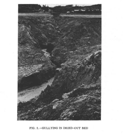
In the course of six weeks, this small flow of water, originating not far from the original shore line as an accumulation of seeping ground water, eroded a gully (FiS. 2). Before the necessary diversion work was completed, at the end of the sixth week, this gully was 36 ft deep and over 60 ft wide. The eroded soil was varved clay, with reasonable strength and a stiff con-sistency. Erosion to the extent noted in such material was one of the most graphic evidences that the writer has ever seen of the necessity for
con-FIG. 2._GULLYING IN DRIED-OUT BED
trolling ground water on construction works, even in such small quantity as could be seen in the small stream that caused this erosion.
GROUND WATER AND THE FIRST TORONTO SUBWAY
Canada's first subway for passenger rail traffic was constructed immedi-ately after World War n by the Toronto Transit Commission in order to relieve what had become one of the worst traffic situations in North
Amer-s M 2
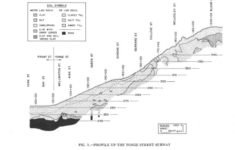
GROUND WATERica. It extends from the downtown Union Station up the main traffic artery of the city for a distance of 4.6 miles. So successful has the subway proved that it is already being extended (as of 1962), as the start of a 10-yr elpan-sion program. The lower third of the route was constructed by cut-and-cover trench excavation beneath Yonge Street; the center third on private right-of-way paralleling Yonge Street partially in open cut and partially by cut-and-cover construction; and the remaining third, also on private right-of-way, was enflrely in open cut, An extensive prograrn of subsurface e:rploration was performed in advance of construction; the soil and rock conditions thereby revealed are shown in Fig. 3. I_t will be seen that only in the upper part of the subway was sand encountered.'r
Thirty of the original test borings were cased with perforated pipes and ground-water levels were read in them at2-weekintervals until the beginning of construction. Some variation was noted in the levels observed in the clay strata but these were purely local; the groundwater in these holes was held in the fissures of theweatheredupperpartof the clay and glacial till deposits. Records obtained from the holes in the sand, however, showed regular varia-tion with local precipitavaria-tion. Study of these records enabled accurate pre-dictions to be made of the performance ofthe ground water when construction started. No unusual problems in the open-cutworkwere encountered, because tlre grade of the subway facilitated drainage by gravity.
There was, however, one somewhat unusual condition in the vicinity of the College Street Station (Fig. 3). It was knownthat trouble with "quicksand" had been encountered some years previously during the construction of tle founda-tions for a large building atthislocation. As soon as test boring records were studied, the reason for this became obviousbecausethe sand strafum forming the ground surface further up Yonge Street here dipped beneath the clay that formed the surface at College Street, The ground water in the sand was, therefore, confined by the overlying impervious clay. It was possible to esti-mate the sub-artesianpressure under which the ground water probably existed, a condition that readily e:<plained the tales of "quicksand" in this locality that had been passed down in Toronto constructlon circles ever since the trouble with the building foundation. It was desirable to check this prediction in ad-vance of the construction of the subway. The Toronto Transit Commission, therefore arranged for a deeper test borlng tobe put down from the bottom of the basement of a new building at this location; the record obtained is shown in Fig. 4. When the claywaspenetrated, ground water immediately rose in the casing to within 12 in. of the calculated level. Information as to this critical ground-water conditlon was provided to all bidders on the main contract. It was taken into fullconsiderationbythecontractorsfor this part of the subway, special care being exercised in the excavation of the clay at this location. The example shows the necessity of sinkingtestholes to proper and sufficlent depth for giving complete information about all ground-water conditions on constructlon sites. All too often shallow borings are thought to be sufficient.
GROUND WATER AT FORESTVILLE. QUEBEC
The Sault-au-Cochon is one of the smaller riversflowing into the St. Law-rence on what is widely known as the "North Shore" (tle south coast of the
7 sSite Investigations for Canada,s Firet Underground Railway," by R. F. l,egget and W. R. Schriever, Civil Eneineerins and Public Works Review. VoI. 55, 1960, pp. ?3-80.
SOIL SYMBOLS WATER LAlo SOILS: ICE LAID SoILS:
A CLAY Q cttttt ttu-ffi srrr ffi srlrv rtl E SAND,GRAVEL N sANoY TILL
n CLAY WtfH 14 SANDY LENSES ttn CLAY AND S|LT, * vARvED CLAY I RocK F q a o o J 6 o o o a r J f U
=
F @ 2 U U YONGE ST, F q F z a P o o z= =
J U = o + o F o t -Y G >9 6
F R O N T S I t J-(o t9 32O -3 t o _ 3OO 29O 2 8 0 27O -a t9 25O-l_:""_
s M 2
GROUND WATERUngava-Labrador peninsula). It enters ttre Gulf over a singularly beautiful waterfall that, unfortunately, complicatesthehandlingofthepulpwood regular-ly coming down the river. The small shipping port of Forestville, developed for the trans-shipment of this pulpwood, was therefore located approximately 1| miles from the mouth of the river, to whieh it is connected by a road and a log flume, the latter taking off from a convenient ponding area above the waterfall.8 while engaged on advising with regard to the harbor development, the writer was asked to examine the route proposed for this log flume and here encountered another ground-water problem.
Log flumes do not often come within the purview of civil engineers, but they are a singularly important partoftheinstallations necessary for
collect-I T r L E E r o x E s
t r € L L s E r r l t o l 9 . 5 i S A T O Y C L A Y , C l t l l o . o J l l o u € H )
-( t o 0 G H l
FIG. 4.-CROSS-SECTION T}IROUGH TEST BORING AT COLLEGE STREET ing pulpwood from the rivers down which it is floated, and for conveying it either to the paper mill or loading berths for transportation to distant mills. At the upper end of the Forestville flume, and at its lower end adjacent to the shipping wharf, the trestles supporting the flume couldbe founded on bedrock. The greater part of thelengthoftheflume, however, had to be located parallel to the access road, along a curving coastline. Much of the exposed soil was sand but some strange signs of seepage of ground water were also noHced.
8 sDevelopment of a Pulpwood Shipping Harbour, Forestville, Quebec,' by R, F. Leg-get, Engineering Journal. Vol. 36, October, 1953, pp. L287-7294.
E L E V 3 4 0 330 3 2 0 STANDING COLUMN rN casrIgElEL S A N O W A S P E N E T R A T E O TOP OF SAiID
10 April, 1962 S M 2 This led to a careful study of the surficial geology along the route. Wave-cut Iow banks below the road showed the exposures of the Leda clay that is such a distinctive feature of soils in the St. Lawrence valley. In this part of the Gulf, the clay is unusually hard and quite impervious. A few simple auger borings shoured that it was continuous under the surface sand deposits, thus providing a perfect trap for any groundwater in the overlying sand, Borings
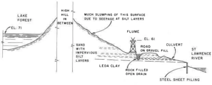
showed also that, as usual, these post-glacial soil deposits were irregular, so that the possibility of movement of footings for the flume-trestles was obvious. A simple drainage system was designed to capture all ground water flowing down the mainsurfaceoftheLedaclay towards the shore line, because any concentration of ground water would be liableto cause soil movement and possible trouble with the alinementof theflume. Fig. 5 illustrates the drainage system that was installed,
Interest was aroused as to the origin of the seepage evident on the slope described. At the time, the area was newly opened up and the first over-all surveys were then in progress; general maps, therefore, were not available. It was not too surprising to find, when the area beyond the crest of the slope
T U C A S L U i l P I N G O F T H I S S U R F A C E H I G H H I L L A T S I L T L A Y E R S F L U M E R O A O C U L V E R T O N G R A V E L F I L L L E D A C L A Y R O C X F I L L E D O P E N D R A I N
FIG. 5._CROSS-SECTION THROUGH LOG FLUME AND ACCESS ROAD
from the shore was explored on foot, that a small lake lay immediately adja-cent to the hill top, at an elevationmuch higher than the location of the flume. Most fortunately, this was noted just before those responsible for the logging operations decided that the lake would be helpfulto them as a source of water if its level were raised a few feet, Although an accurate survey up and over the slope to the trake has notbeennecessary, so that only a sketch can be used to illustrate this point, Fig. 5 shows how serious any rise in the level of the lake would have been. The loggers were dissuaded from their initial plans, and the lake remains (as of 1962) at its original elevation.
Log flumes have the desirable feature of providing their own indication of any settlement of their foundations. The slightest change in the elevation of even one bent immediately showsinthewatersurface in the flume. It is satis-factory to record that, although now in steady operation for approximately
15 yr (as of 1962), the Forestville flume has shown no sign of movement. The entire bank along whichit and the adjacent access road to the wharf are located
s M 2
GROUND WATERFIG. 6.-GENERAL VIEW OF THE FORESTVILLE LOG FLUME, QUEBEC
1 1
L2 April, 1962
s M 2
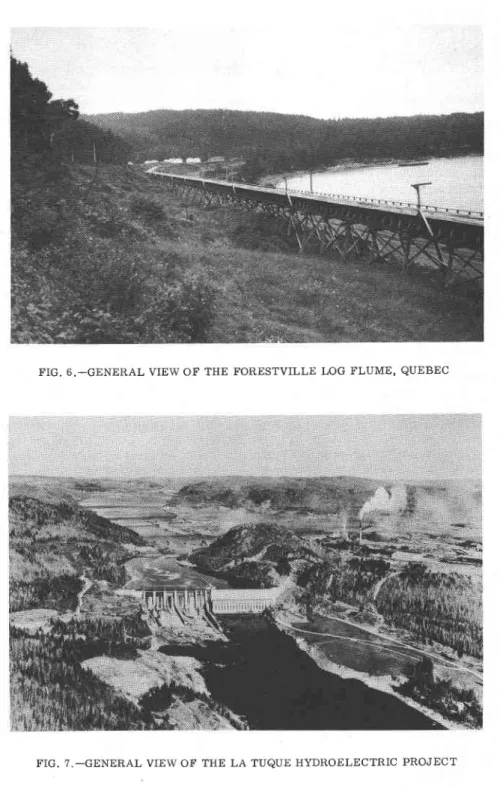
has been completely stabtlized by the simple drainage system described. A general view of the Forestville log flume ls shown in Fig. 6.
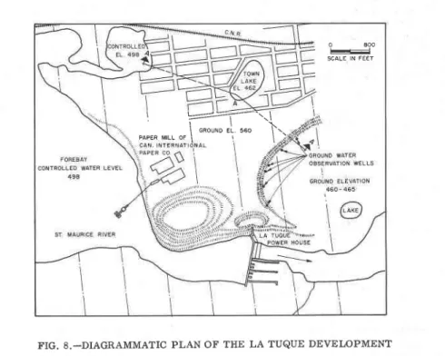
GROI'ND WATER AT THE LA TUQUE ITYDROELECTRIC PROJECT, QUEBEC A hydroelectric plant was eonstructed on the St. Maurice River in Quebec immediately to the west of the town of La Tbque during 1939 to 1941 with an initial capacity of 192,000 hp generated under a head of 114 ft.9 The power-house is integral witl the main dam that was_built in what used to be a rocky gorge through which the river flowed for apprordmateLy 3/4 mile, dropping approximately 90 ft between upper and lover pools. To the west, the ground rises steeply from the original river bed, the dam finishing as a small core wall carried well into the glacial till that forms tJle western river barik. To the east of the powerhouse the dam abuts on to a high rock face cut into the downstream end of one of the two granite "knobs" that form an unusual feafure of the local landscape. The townof LaT\rquetakes its name from the upstre.rm knob. The two rock knobs standoutfroma f{irly level areaof ground stretch-ing approximately 1 mile to the east before steeply rising ground is again reached. The surface of this plain is approximately 60 ft above the forebay level, On it are located tlte town of La T\rque and a larger paper mill, as shown in Fig. ?.
This level plain continues at approximately the same elevation for some distance downstream but has a varyingwidth. Alarge area immediately down-stream of the powerhouse is at an elevafion of 46b ft or approximately 100 ft below the level of this plain. The drop between the two areas occurs as a steeply sloping bank curved in plan to remarkably regular ouiline. It is known that the preglacial valley of the st. Maurice River lies under these two level areas. Geophysical enploration has disclosed the depth to bedrock to be ap-proximately 500 ft. The old preglacial river valley is now filled with unsolidated material derived from glacial deposits. In general, the ground con-sists of uniformly graded sand but somelensesof gravel also occur. The vast extent of this pervious area naturally precluded any attempt to provide a cut-off across it.
Accordingly, it was anticipated that when head-water elevation was raised to its normal operating level, there woutd be a substantial change in the local ground-water situadon. Preliminary calculations suggested that the rise in ground-water level at the foot of the steep slope would not bring the ground-water level up to the surface level of the lower area, although it would be cl.ose to it. A series of observation wells were, therefore, installed along the foot of the slope at the outset of construcfion (Fig. 8). Regular readings in these wells confirmed the original calculations. After it had reached a new state of equilibrium, the ground-water level remainedreasonablyconstant, as observed in these observation wells, located immediately to the southeast of the powerhouse.
The more unusual feature of this projectisthat in the center of the town of La T\rque there isasmallexpanseof water, long known as the Ton'n Lake, that fills a crater-Iike depression in the general ground surface. Before con-struetion of the power plant, its normal elevation was approximately 462 ft above sea level. It had no apparent inflow or outflow, the local explanation . I sConalruction ofllydro-llectric Development of La Tuque,'by J. A. McCrory, En-Aineering Journal. Yol.24, Februa.ry, 1941, pp. b4-68.
SM 2 GROUND WATER 13 being that it was "fed by springs." This is apopular way of sayingthatthe
lake was direct evidence of the general ground-water level, disClosed in this way because of the bottom level of the depression that it filled.
It was to be e:rpected,inviewof the location of the lake, that its level might change when the water in the reservoirbehindthe dam rose to its final opera-ting level. This proved to be the case, the level of the lal<e rising almost 5 ft soon after the main gates on the dam were first closed. This rise in water level threatened to interfere with the operation of town sewers that encircle the lake. A temporary pumping plant was installed, therefore, in order to correct the situation. The plant consisted of a 1600-gpm pump driven by a 40-hp motor discharging directlyintoasewermanhole. It was found'that, alter
FIG. 8.-DIAGRAMMATIC PLAN OF THE LA TUQUE DEVELOPMENT 3 days of continuous pumping, the water level in the lal<e was reduced by ap-proximately 2 ft, thus bringing the level of the lake down to a safe elevation in relation to the sewers.
The pumping installation was later made permanent and has operated inter-mittently ever since. No diffieultyhasbeenexperienced (as of 1962) in keeping the lake level down to a safe elevation. Fig, 9 shows, in diagrammatic form, the over-all gradients of the ground water between the head pond, the Town Lake, and the foot of the steep slope, as they were before construction of the dam and after the rise in the head-pond level. The existence of a permanent pumping installation to correct the natural movement of ground water is un-usual. The success that has attended this simple solution to what could have
o aoo
-S C A L E I N F E E T I L->- -\\\ \ n"or"o ,1. ,"o \.. P A P E R M T L L O F I ! l . . r :1 4 April, 1962
s M 2
been a difficult problem provides yet another example of t}e importance of careful studies of ground water in relation to construction projects.
GROI'ND WATER AT THE
AGUASABON HYDROELECTRIC PROJECT, ONTARIO
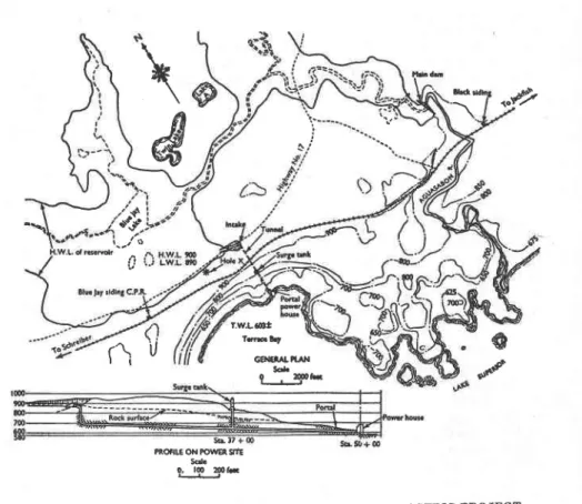
Between 1946 and 1948 the Hydro-Electric Power Commission of Ontario completed its Aguasabon power plant on thenorthshore of Lalce Superior, ap-proxirnately 130 miles east of Port Arthur (FiS. 10). This plant has an in-stalled capacity of S4,000hpgeneratedunderahead of 290 ft. Water is brought to the small powerhouse located on Terrace Bay through a 15-ft diameter tunnel leading to twin steel penstocks. The Aguasabon River enters Lake Superior approximately 2 miles tot}e eastof tlte powerhouse, its water having been impounded by a concrete dam approximately lf miles from the mouth. Unusual local topography results inthereservoirsoformed extending not only up the river in the usual way, but flooding through a narrow gorge just above the dam into a large basin-shaped area to the west of the river, extending to
FoREE^Y | | | l/r^corrRoLLED ErEvrTroN 493 t t \ I TOWrI LAkE zxAxx
'-,/
tur w.L. 475 \oRrGruL nrvER --l\ \ -'1 LE'EL485 "i:::J.F
tr--
$
1 1 4 6 2__w,
M.22tl
r,ooo 2,oo0OISTANCE FROM FOREEAY (FT}
T'IG. 9.-CROSS-SECTION FROM THE LA TUQUE HEAD POND TO THE OBSERVATION PIPES BELOW THE POWER HOUSE
within I mile of the shore of the lake, and yet 290 ft above it (at reservoir water line). Superficial examination of local rock outcrops suggested that the ridge between the reservoir site and the lake would be of solid rock, even though covered with a mantle ofsoil. Theusual careful preliminary test dritl-ing of Ontario Hydro, however, penetrated to depths well below lat<e level along this ridge with nothing revealed but sand and gravel, the presence of many boulders eliminating any possibility of constructing a cut-off wall (even to such a depttr) between the adjacent rock outcrops, and considerably com-plicating the drilling work.
Sfudy of the natural basin directed attention to a small pond of water, Blue Jay Lake, in its center, apoolthatcould only have been retained by underlying impervious materials. The glacial history of this part of northern Ontario suggested that this might be a layer of glacial silt similar to other glacial lake deposits in this part of the Canadian Shield. Trenching around the edge of the reservoir area, and careful test drilling (with a minimum number of holes actually penetrating the blanket) revealed a continuous bed of compact
SM 2 GROT'ND WATER 15 and almost impervious glaeial silt over the entirebed of the basin, extending, most fortunately, approximately to the intended top waterlevel for the reser-voir. Tests were made to determine by penetrationtlte depth of the silt layer. where this was studied it vas found to be a relatively few feet, thinning out towards its upper edge. With the knowledge of this natural reservoir lining, and assuming that it wag continuous, planning of the proiect could be com-pleted.
The plant was built; the reservoir was filled. There was a slight increase in the level of the ground water in the sand and gravel almost 300 ft beneat}
lhd
n &
\
&
r\
'u
rw.La6t t@lt GilEtA|,?I'N SoL t-_3Ph s r , + PROf|LE ON FOWEn Snl SqL 0, lO z00tFIG. 10.-GENERAL PLAN OF THE AGUASABON HYDROELECTRIC PROJECT the reservoir, but this gradually levelled off and the plant has been in con-tinuous operation ever since its opening, dependent for its water supply on this nafural "perched" reservoir. 10
CONCLUSIONS
The foregoing examples suggest some simple conclusionsthatmay be pre-sented in the form of suggestionswithregardto the necessary study of ground
10 'A tPerched' Reservoir in Northern Ontario, Canada,' by R. F. Legget, G6otech-nique, Vol. 3, June, 1953, pp. 259-265.
o
"ttf
('$'
16 April, 1962 SM 2
water in relation to construction operations:
1. Investigation of ground-water conditions must be an integral part of all subsurface invesdgations of sites to be used for civil engineering projects. Observations of grotrnd-water levels, seepage, and associated phenomena should always be correlated, as subsurface investigations continue, with the developing picture of the local geology.
2. In all investigations of ground-water conditions, the dynamic character of ground water must be keptinmind, both with regard to movement of ground water and the fact that ground-water levels will almost eertainly be found to vary throughout the year and possibly also from year to year. Recordings of ground-water level variations should therefore,bemadeforthe longest possi-ble period, and certainly for never less than one full year.
3. Beeause of the dynamic aspectof groundwater, investigations of ground-water conditions should not be restricted to the building site if there is the slightest chance of construcfion operations affecting or being affected by ground-water conditions removed some distance from the site itself.
4. In all such work the three-dimensional aspect of the problem should be kept in mind because sometimes this will profoundly affect the significance of individual observations; this may frequently be conveniently done by using three-dimensional peg models.
5. The dependence of ground water on rainJall should always be kept in mind. In interpreting their inter-relationship, theconceptofground-water de-pletion as devetopedll ty C. W. Thornthwaite will be found to be a powerful tool,
6. Following the completion of civil engineering works that have been in-fluenced by, or are liable to influence, local ground-water conditions, contin-ued inspection for a period of several years following the complefion of the work will always be essential.
ACKNOWLEDGMENTS
The writer is indebted tothose responsibleforthe projects mentioned, with whom he had the pleasure of working, for permission to mention their work in this paper; in particular, M. S. Fotheringham, President and General Manager of Steep Rock Iron Mines Ltd.; W. H. Pattterson, General Manager, formerly Chief Engineer, Subway Construction, Toronto Transit Commission; J. O'Hall-oran, Chief Engineer, Anglo Canadian Pulp and Paper Mills, Ltd.; and Otto Holden, F. ASCE, lately Chief Engineer, Hydro-Electric Power Commission of Ontario (now retired). The writer is also indebted to Richard E. Hearlz, F. ASCE, Chairman of the Board of the Shawinigan Engineering Co., Ltd., for permission to describe the La T\rque example, which the writer has had the privilege of visiting and studying.
11 "An Approach Toward a Rational Classification of Climate," by C. W. Thornth-waite, GeoAraphical Review. Vol. 38, 1948, pp. 55-94.
s M 2
GROUND WATER l 7 L . 2 . 3 . 4 . o . 6 . 8 .APPENDTX.- ADDITIONAL RE FERENCES
"Applied Hydrology," by R. K. Linsley, M. A. Kohler, and J. L' H' Paulhus,
McGraw-Hill Book Co., Inc., New York, N' Y.' 1949.
"Hydrology for Engineers," bY R. K. Linsley, M. A. Kohler, and J' L' H'
Paulhus, McGraw-Hill Book Co,, Inc., New York, New York, 1958'
,,The occurrence of Groundwater in the united states, with a Discussion of
Principles," by O. E. Meinzer, w4gl rypply i3!9l-l!9.199, Geol. Survev,
u. s. Dept. of the Interior, wash@3.
"Plants as Indicators of Groundwater," by O. E. Meinzer, yatsrgrpPU Paper No. 5??, Geol. Survey, U. S. Dept. of the Interior, Washington, D. C., t921.
"Ground Water Hydrolog:y," by D. K. Todd, JohnWiley and Sons, Inc., New
York. N. Y. 1959.
"Ground Water," by C. F. Tolman, McGraw-HillBookCo., Inc., New York,
N . Y . . 1 9 3 7 .
"Methods for Determining Permeability of Water-Bearing Materials," by
L. K. Wenzel, Paper No. 88?, Geol. Survey, U' D. Dept. of the Interior' Washington, D. C., 1942.
"Hydrolog'y," by C. O. Wisler and E. F. Brater, John Wiley and Sons, Inc',

![[Beta-carotene is associated with lower risk of some cancers in women nonsmokers but with higher risk in women smokers]](data:image/gif;base64,R0lGODlhAQABAIAAAP///wAAACH5BAEAAAAALAAAAAABAAEAAAICRAEAOw==)