CONTROLLING A FIELD TEST
ELECTRON BEAM-GENERATED PLASMA SYSTEM
FOR THE DECOMPOSITION OF
CHLORINATED VOLATILE ORGANIC COMPOUNDS
IN AIR STREAMS
by
Matthew P. Schuetze
B.S.E., Engineering PhysicsThe University of Michigan, December 1992
Submitted to the Department of Nuclear Engineering in Partial Fulfillment of the Requirements for the Degree of
Master of Science
at theMassachusetts Institute of Technology
May 1994C Massachusetts Institute of Technology 1994 All rights reserved
Signature of Author
Departg4t of Nuclear Engineering May 19,1994 Certified by
Daniel Cohn, Ph.D. Senior Research Scientist and Acting Assistant Director, Plasma Fusion Center Thesis Supervisor Certified by
Professor Mujid Kazimi, Ph.D. Ch,, Department of Nuclear Engineering Thesis Reader
Accepted b e
Professor Alan Henry, Ph.D. Chairman, Departmental ommittee on Graduate Studies
CONTROLLING A FIELD TEST
ELECTRON BEAM-GENERATED PLASMA SYSTEM
FOR THE DECOMPOSITION OF
CHLORINATED VOLATILE ORGANIC COMPOUNDS
IN AIR STREAMS
by
Matthew P. Schuetze
Abstract
Present methods of treating hazardous chlorinated volatile organic compounds
("VOCs") in dilute concentrations in air are generally inefficient or very expensive. A
new, low cost, energy selective treatment method under development uses a 150-175
keV electron beam to generate an atmospheric-pressure plasma through which the
contaminated air stream flows. The plasma, and therefore the level of contaminant
destruction, is highly controllable through the adjustment of electron beam voltage
and current. This paper discusses the control aspects of an electron beam generated
plasma reactor and its role in a complete field-test remediation system.
Accomplishments include the automation of a 150-175 keV electron beam for
computerized control, the incorporation of a Fourier Transform Infrared Analyzer as
a setpoint generator for closed-loop control of the plasma reactor, and the
implementation of a personal computer-based data acquisition and control system for
the coordinated operation of the entire plasma reactor field test system. Initial field
tests of the plasma remediation system will occur at the U.S. Department of Energy
("US DOE") Hanford facility through the US DOE VOC-Arid Integrated
TABLE OF CONTENTS
1. INTRODUCTION ... 5
2. RESEARCH MOTIVATION, ACCOMPLISHMENTS, AND GOALS ... 8
2.1 CRRENT REMEDIATION TECHNOLOGIES ... 8
2.2 COLD PLASMA PROCESSING: A NEW AND IMPROVED REMEDIATION TECHNOLOGY ... I 2.3 CONTROLLING A COLD PLASMA PROCESSOR ... 16
2.4 FIELD TEST OF COLD PLASMA PROCESSOR AT HANFORD, WA ... 19
3 AUTOMATION OF AN ELECTRON BEAM FOR USE AS A PLASMA REACTOR ... 21
3.1 THE PLAS A REACTOR ... 21
3.2 ELECTRON BEAM MODIFICATION ... 24
3.3 PLASMA REACTOR DiMENSIONS/AiR STREAM PARAMETERS ... 29
4. ON-LINE GAS COMPOSITION ANALYSIS AND EEDBACK CONTROL ... 34
4.1 EXPERIENCE WITH GAS ANALYSIS ... 34
4.2 COMPOSITIONAL MONITOR PERFORMANCE CRITERIA ... 35
4.3 GAS ANALYSIS BY FOURIER TRANsFoRm INFRARED SECTROMETRY ... 37
4.4 A DAPTIVE CONTROL ... 40
4.5 DOSE MAPPING CONTROL SEQUENCE ... 44
5 CONSTRUCTION OF A PC-BASED DATA ACQUISITION AND CONTROL SYSTEM ... 52
5.1 C ONTROL V ARIABLES ... 55
5.2 CompuTER/DATA AQUISITION RESOURCES ... 59
5.3 REM OTE O PERATION ... 60
6. FINAL PROJECTED LAYOUT OF FIELD TEST SYSTEM ... 62
6.1 D RYER O PERATION ... 64
6.2 SCRUBBER O PERATION ... 66
7 CONCLUSIONS ... 69
7.1 S UM ARY ... 69
7.2 SUGGESTIONS FOR FUTURE WORK ... 70
TABLE OF FIGURES
]FIGURE 2 1: DIAGRAM OF EXPERIMENTAL SETUP FOR INITIAL TESTS OF CCI4, C2HCL3, AND CHCL3
DESTR UCTION ... 14
FIGURE 22: DEPENDENCE OF DRY CCL4 DECOMPOSITION ON SPECIFIC ENERGY DEPOSITION AND INITIAL INLET CONCENT AION ... 15
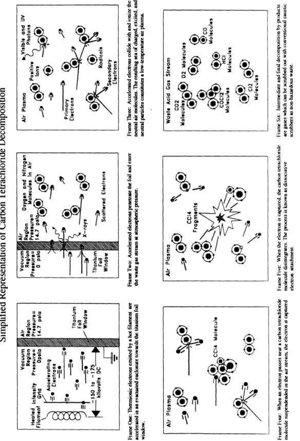
]FIGURE 31 SIMPLIFIED REPRESENTATION OF PLASMA DECOMPOSITION PROCESS ... 23
FIGURE 32 DAGRAM OF PLASMA REACTOR ... 25
FIGURE 33: LECTRON BEAM SCHEMATIC DIAGRAM . ... 26
FIGURE 34: SAMPLE OF ORIGINAL AND MODIFIED VARIABLE TRANsFoRmER
ciRcuns ...
27
FIGURE 35: ELECTRON BEAM IRRADIATION UNIFORMITY PROFILE ... 31
FIGURE
36 AR
VELOCITY NIFORMITY PROFILE...
31
FIGURE
4 1 A
SIMPLE NUCHELSON INTERFEROMETER AND THEKVB/ANALEcT
TRANSEPT INTERFEROMETER.38 ]FIGURE42:
DIAGRAM OF A SIMPLE, GENERIC FEEDBACK LOOP ....
41
FIGURE
44:
DOSE MAPPING FOR SPECIFIEDDRE
OR SPECIFIED FINAL CONCENTRATION ....
48
FIGURE
5. 1:
CONTROL SYSTEM SCHEMATIC DIAGRAM SHOWING TYPICAL FEEDBACK LOOP CONFIGURATToNs.58FIGURE
6 1:
BLOCK DIAGRAM OF PROJECTED FIELD TESTssT'Em
. ...
63
FIGURE
62:
DESICCANT DRYER SCHEMATIC DIAGRAM. ...
65
Twenty years ago, government and industry disposed of their toxic waste solvents by
burying them in the ground. Chlorinated volatile organic compounds ("VOCs"), such as
carbon tetrachloride and trichloroethylene, comprise the largest amounts of industrial
solvents dumped. These hydrocarbons are routinely used in large quantities for metal
degreasing, dry cleaning, and paint stripping. Many of these compounds, classified as
hazardous, have induced cancerous tumors in lab rats, are suspected to be human
carcinogens, and, in the presence of nitrogen oxides, form ground-level ozone, itself a
hazardous compound[ I J.
The improper disposal and subsequent dispersion of these compounds into the
groundwater creates a public health risk. Although the U.S. Environmental Protection
Agency ("US EPA") heavily regulates the present production, distribution, and use of
most hazardous materials in the U.S., much of the dumping occurred several decades ago,
1. Introduction
solvents from soil and groundwater and treating them in preparation for final disposal, is
quite expensive. Current extraction techniques are fairly successful in recovering VCs.
However, present treatment methods are ineffective. They can be expensive, can create
hazardous byproducts, do not offer final disposal, or must be performed off-site.
Using low-temperature plasmas, researchers at the Massachusetts Institute of
Technology Plasma Fusion Center ("PFC") and supported by the U.S. Department of
Energy ("US DOE") through the Volatile Organic Compound-Arid Integrated
Demonstration Program ("VOC-Arid ID") have developed a new, low cost technology for
complete on-site treatment. Focusing on the chemical and physical nature of solvent
decomposition by plasma processing, researchers at the PFC have studied the feasibility of
using electron beam-generated plasmas to break up chlorinated VOCs in laboratory
experiments. Initial investigations indicate that substantial savings in cost and energy
expenditure may be possible by using plasmas instead of conventional technology for low
concentration waste streams. However, the development of a complete field-operable
demonstration system will act as a better indicator of the viability and cost-effectiveness of
this process. Moreover, demonstrating automatic and remote control of the complete
system would optimize the efficiency of the process and eliminate the need for
around-the-clock staffing during continuous-duty operation.
The author of this thesis has designed and implemented the automatic control
infrastructure necessary for adaptive operation of a demonstration plasma reactor-based
modification of a 150-175 keV electron beam for automatic control, the incorporation of a
Fourier Transform Infrared ("FTIR") gas composition analyzer into a follow-up,
limit-cycle control loop, and the design and implementation of a personal computer-based
control system for the coordinated operation of the entire system. As the author
completed this work in context of a team engineering project, the author discusses, where
necessary, background information and general aspects of the project.
This thesis is organized in the following way. Chapter Two focuses on the status of
the new VOC remediation technology and the plans for field testing of the plasma
treatment system. Chapter Three describes the author's work in designing and
implementing automatic controls and indicators for the 150-175 keV electron beam. In
Chapter Four, the author discusses the operation and use of an TIR gas composition
analyzer and its role in various closed-loop control algorithms. Chapter Five outlines the
author's work in selecting and assembling instrumentation for a personal computer-based
control system to oversee operation of the entire field unit. Chapter Six describes the
projected layout of the trailer-based plasma remediation system, operation of the scrubber
and dryer subsystems, and aspects of integrated control of the full system. Chapter Seven
2.1 Current Remediation Technologies
Remediation of sites polluted by the improper disposal of these hazardous compounds
requires two steps. First, the contaminants must be extracted from the soil or
groundwater. Two present technologies -- soil vapor extraction and air stripping -- work
to recover organic solvents from contaminated soil and groundwater. Both recovery
techniques make use of the volatility, or high vapor pressure, typical of most VCs In
soil vapor extraction, vacuum pumps suck air from wells cut into the contaminated
ground. While soils exist as inhomogeneous solids, small air pockets reside between soil
particles. The vacuum extraction process pulls the air from these pockets, and along wth
the air comes the evaporated chlorinated solvent. In air stripping, clean air is sparged or
bubbled through the contaminated water. Hydrocarbons generally have low solubility in
water. Thus, when presented with a medium for escape like clean air, the concentration
gradient kicks the solvent molecules from the water into the air. The hazardous waste
emerges from both soil vapor extraction and air stripping as an air stream near
atmospheric pressure.
The second step of the remediation process involves the treatment of the air stream
carrying dilute concentrations of gas-phase solvent. The four most common treatment
alternatives presently used for gaseous VOC destruction are incineration, catalytic
oxidation, gas-phase concentration followed by incineration or catalytic oxidation, and
liquification followed by incineration or catalytic oxidation. As indicated below, none of
these alternatives adequately treats low concentration gas streams.
The first of these alternatives, incineration, involves the burning of organic
contaminants in flames. Incineration does not effectively treat low concentration
(1-1000 ppm) streams because energy use is non-selective and therefore highly inefficient.
Although many solvents will undergo combustion in a hot flame, a large fraction of the
added energy goes towards raising the temperature of the background gas while only a
small fraction actually destroys the contaminant molecules. In addition, maintaining a hot
flame requires an auxiliary fuel stream, which upon its own combustion adds considerably
to the overall mass of the waste stream. Finally, incineration of chlorinated VCs
produces phosgene a highly toxic gas. Without scrubbing mechanisms to dissolve and
break up this gas, release of phosgene after combustion may be more hazardous than the
original VCs. Although wet scrubbing technology is presently used on sorrie incinerators,
the cost of refitting existing incinerators with add-on scrubbers is apparently very
The second treatment method, catalytic oxidation, differs from incineration only by
using catalysts to induce the same chemical reactions at lower temperatures. Although
catalytic oxidation successfully reduces the high operating temperature necessary for
solvent combustion, energy addition is still non-selective. Moreover, replacement of
precious metal catalysts is generally quite expensive. As with incineration, this process
also generates phosgene as a reaction product.
Gas-phase concentrators, the third current treatment alternative, work by
adsorbing VCs on porous media, such as granular activated charcoal ("GAC").
Adsorption in GAC canisters provides for excellent capture and recovery of low
concentration solvents and, upon canister regeneration, results in higher concentration
solvent streams more suitable for combustion. However, GAC is quite expensive.
Moreover, using GAC requires an added stage in the waste handling process and does not
provide for final disposal of the hazardous material. Unless an incinerator is available
on-site, the waste canisters must still be transported to an incinerator or other suitable
treatment facility.
Finally, liquification, the fourth treatment method, involves the use of membranes
to liquefy the solvent waste stream. Membranes are not effective for treating low
concentration streams because they require the VCs to be near their saturation limit.
with liquification is that, as with GAC, it does not offer final disposal: incineration or some
other suitable final treatment, either on- or off-site, is still required.
2.2 Cold Plasma Processing: A New and Improved Remediation
Technology
The inefficiencies of the current treatment methods demonstrate the need for an on-site,
single-stage process for treating the dilute waste stream in a contaminant-selective and
energy-efficient manner. A cold plasma process has been developed and tested in
laboratory experiments at the PFC which satisfies these initial requirements. In addition, it
creates primarily non-hazardous inorganic gases and salts as final waste products.
The cold plasma process consists of three parts. In the fst stage, a desiccant dryer
removes water vapor from the contaminated waste stream. In the second stage, an
electron beam irradiates the dried gas stream, generating a highly-reactive
low-temperature plasma which decomposes the chlorinated VCs into mostly carbon oxides,
chlorine, and hydrochloric acid. In the third stage, a caustic scrubber stabilizes the still
highly-toxic chloride compounds into sodium salts via acid-base chemistry, while the
carbon oxides are vented to the atmosphere.
Although the first and third stages are established chemical engineering practices,
the second stage represents an innovative use of plasma for chemical processing. In the
temperature, air is composed of a mix of gases, dominated mostly by nitrogen and oxygen.
Even though an extremely small fraction of this gas continually undergoes ionization by
cosmic rays and natural background radioactivity, most gas atoms exist as bound,
neutrally-charged molecules. The electron beam provides a source of electrons sufficiently
energetic to ionize air molecules. The ionization products, including free electrons, excited
atoms, radicals, and ions, are charged or excited.
Such a collection of charged, excited, and neutral particles is specifically called a
non-thermally equilibrated plasma since each species (electrons, ions, neutrals) may
independently exhibit a spread of energies not at all resembling a Maxwellian distribution.
The electrons can heat up while the ions and background gas remain relatively cold. The
useful property of such a reactive collection of particles is their ability to induce chemical
reactions that may oherwise only occur at high temperatures. In particular, a type of
chemical reaction known as dissociative electron attachment appears to drive the
decomposition process for the chlorinated VCs of interest through the ionization
cascade.
Efforts at testing the viability of plasma-induced decomposition of chlorinated
organic compounds started with the construction of a laboratory scale beam and reaction
cell. At first, simple flow systems made from Tygon tubing, a rudimentary electron beam
built from scavenged parts and equipment, and an elementary caustic bubbler were hastily
quality gas chromatograph and thereafter a mass spectrometer, allowed for improved data
accuracy. Benchmarks were established for destruction and removal efficiency, byproduct
identification and quantification, and irradiation dose requirements for various contaminant
inlet concentrations and air flow rates. Early work is documented in papers published in
Physics Letters A in 1993 2 J3
The three compounds scrutinized so far include carbon tetrachloride, chloroform,
and trichloroethylene. The experimental setup used in determining benchmark destruction
and removal data for carbon tetrachloride (CC14), trichloroethylene (C2HClA and
chloroform (CHC13
ioutlined in Figure 2 .
Destruction efficiencies were measured as functions of the following parameters:
•
electron beam voltage
•
electron beam current
• air volume flow rate • initial inlet concentration
•
superposed sub-breakdown DC electric field voltage
• carrier gas composition, i.e. varied oxygen, nitrogen, and argon concentrations • air stream water vapor content, i.e. relative humidity
The results of this data, generated by Mathias Koch and discussed in detail in his doctoral
thesis, show the anticipated strong dependence of decomposition on increased beam
current, decreased air mass flow rates, and decreased initial inlet contaminant
from approximately 40 eV per molecule at 60% destruction efficiency to about 100 eV per
molecule at 95% destruction efficiency. C2HC13 destruction requirements were observed
to be one order of magnitude lower than those for CC14 with a similar
approximately-exponential dependence on destruction efficiency 4 .
Flowmeter omega FL 22 . Matheson E03 or Matheson E05
0 must od A %.U or (I 00 all) (050 ML) Bubbler (100 ml)
Figure 21: Diagram of experimental setup for initial tests Of CC14, C2HC13,
and
CHC13 destruction 2].
Figure 2.2 shows representative destruction efficiencies for dry carbon
tetrachloride decomposition achieved with the lab beam, displaying exhaust concentration
as a function of absorbed dose and initial inlet concentration. Absorbed dose is calculated
from beam power, air mass flow rate, and power deposition efficiency.
CO 4 Decomposition WM
T
M mo Im C 0 T C 10 0 t) C 00
la I 3 M X LIj 0.1 O IV, 663 pprn (.08 Ornin) v---v 352 pprn (.18 Ornin) c3---Ei 166 pprn (.35 .1'./min) 26 pprn (.35 ft /min) 0 100 200 3WElectron Beam Power Deposition [kW/(kg/s)]
Figure 22: Dependence of dry CC14 decomposition on specific energy deposition and
initial inlet concentration. 3]
Measured byproducts from carbon tetrachloride and trichloroethylene
decomposition include primarily chlorine gas, hydrochloric acid, carbon monoxide, and
carbon dioxide. Measured intermediate byproducts include phosgene for carbon
tetrachloride and both phosgene and dichloroacetyl chloride for trichloroethylene. Use of
conventional scrubbing with a basic solution effectively stabilizes each of the above
chloride compounds. For this reason, a packed-tower scrubber was included downstream
from the plasma reactor in the demonstration system design.
For carbon tetrachloride and chloroform decomposition, reductions by factors of
two to four in dose requirement were observed for streams dried to under 150 ppm water
reason, the desiccant dryer was added upstream of the plasma reactor in the field system
design. This relative humidity effect was not observed in trichloroethylene decomposition.
2.3 Controlling a Cold Plasma Processor
Notwithstanding the impressive results of the laboratory experiments, the viability of the
cold plasma treatment system can be proven only through on-site field testing. To date,
the effort has focused primarily on the study of the chemical and physical mechanisms
involved in VOC decomposition via the cold plasma process. To truly gauge the
cost-effectiveness of the process, however, a mobile field-test demonstration system, consisting
of an operational trailer-housed plasma reactor with gas drying and scrubbing subsystems,
is being developed at the PFC A major factor in the cost-effectiveness of the plasma
process is the capacity for remote, unmanned operation. Consequently, the author has
designed and implemented an adaptive, computerized control system as an integral part of
the demonstration unit.
Including a control system in the demonstration unit provides many benefits. A
major motivation for automatic control of the plasma reactor in a remediation system is to
eliminate the around-the-clock manpower requirement and significant associated cost that
comes with continuous-duty operation. Second, significant gains in efficiency can be made
by employing an adaptive control algorithm which can automatically tune process
computerized control is enacted, the jump to remote control is simply a matter of
computer-to-computer communication, a common capability with modem computer
technology.
As the above empirical destruction data indicate, there exists a strong correlation
between contaminant destruction efficiency and absorbed dose. Thus the goal of an
automatic control system is to dial in the proper absorbed dose to destroy the inlet VOCs
to a sufficient level for any given inlet concentration. A inimum of three out of four
system variables must be prescribed to determine the dose and destruction state of the
plasma reactor system for any given inlet concentration. Those are the beam acceleration
voltage, the beam current, the air mass flow rate, and the desired final exhaust
concentration. The work performed for this thesis involved establishing the ability to
control the state of the plasma reactor via this set of variables.
The control system is comprised of various electrical and mechanical hardware
components, two computers, and a half-dozen computer programs. These are configured
to offer measurement and control of all the important plasma reactor parameters from the
computer terminal. Three major steps were performed by the author towards the
automation of the plasma reactor system.
The first step was the design and implementation of personal computer-based data
acquisition and control instrumentation. This included selection and installation of proper
analog and digital input/output electronics, signal conditioning and isolation hardware, and
a graphically-oriented software system for the measurement, control, and display of all
important system functions and variables. Execution of this step required integration of
both hardware and software components.
The second step was the conversion of an Energy Sciences Inc. CB 150
Electrocurtain System electron beam to a computer-controlled plasma reactor. This was
accomplished via the design and installation of several large electrical circuits, including
beam voltage and current transmitters and an array of motor-driven variable transformers.
This step was strictly hardware oriented.
The third step was the incorporation of a KVB/Analect Diamond 20 Fourier
Transform Infrared Gas Analyzer as a setpoint generator in a closed-loop adaptive control
scheme. This included writing several software-implemented routines enabling serial
communication with the analyzer system and employing various models for generation of
setpoint information from gas composition data. Execution of this step was primarily
software oriented, as the Diamond 20 was installed preconfigured by KVB/Analect for the
present measurement needs. However, understanding and adjusting the preconfigured
software, as well as development of original programs, were prime accomplishments.
Although many additional engineering tasks were performed along the way, these
three form the basis for rudimentary control of the complete system. Due to shipping and
individual hardware components, such as the automated beam circuit, and implementation
of closed-loop software algorithms closely resembling those to be used in operation of the
final system each proved successful in benchtop demonstrations. A full demonstration will
be performed shortly, as the remaining construction work reaches completion and final
preparations for field testing are made.
2.4 Field Test of Cold Plasma Processor at Hanford, WA
The first field test of the cold plasma processor will be at the Hanford Reservation, a
former weapons production facility operated by the US DOE located near Richland, WA.
In the past, many pits, cribs, and trenches where dug for use as dumping grounds for
organic solvents at Hanford. One of the largest environmental cleanup operations
presently underway at Hanford involves a large quantity of carbon tetrachloride that had
been directly discharged into the soil. Although carbon tetrachloride had long been
available as a household cleanser, its commercial ban by the US EPA in the 1970s
prompted the end of its wholesale manufacture and subsequently reduced the threats of
continuing carbon tetrachloride pollution. However, the ban came too late to prevent the
Hanford problem: several hundred thousand gallons of carbon tetrachloride were
discharged to cribs in the soil between the 1950s and 1970s. As of June 1993 an
estimated 95% of the initial amount still presently pervades the soil vadose zone, the layer
of soil between the surface and the water table. The ad soil structure at Hanford prevents
rapid transport of suspended contaminants, yet groundwater samplings revealing
indicate that carbon tetrachloride is definitely leaching from the vadose zone to the water
table.[5 I
The US DOE Office of Technology, Development, Environmental Restoration and
Waste Management launched the VOC-Arid ID in order to spur development of new
VOC monitoring, recovery, and destruction technologies necessary to better handle the
enormous soil remediation tasks ahead. As a participant technology in the Integrated
Demonstration, the electron beam-generated plasma system will be used in field testing of
chlorinated VOC destruction on the Hanford site. The trailer-housed plasma reactor will
process a partial stream from a presently-operating soil vapor extraction unit in both
shakedown and endurance trials.
If the demonstration field test goes as planned, then the commercialization of
electron beam plasma technology may be shortly realized. Use of electron beams with
higher voltages and larger current capacities, larger scrubbing and drying towers, and
reaction cells designed for high power deposition efficiency could increase process
throughput dramatically. Pilot scale unit operations would facilitate the cleanup of both
the Hanford plume and other government and non-government sites contaminated with
chlorinated VOCs. Further laboratory research into the decomposition of other types of
solvents or hazardous compounds and identification of their reaction byproducts will
The plasma used to decompose chlorinated solvents in air streams is generated by a
moderate-voltage electron beam. Modification of the commercially-manufactured beam
was necessary to prepare it for computerized operation. Mis chapter describes the plasma
generation mechanism, the author's work in upgrading the electron beam to motorized,
computer-interfaced control, and the performance aspects of the plasma reactor cell as
presently configured.
3.1 The Plasma Reactor
The ionization-driven plasma is generated by a 150-175 keV electron beam. Electron
beam technology has matured for the past century. Early experiments in electrostatics
resulted in rudimentary devices producing controlled streams of electrons. Vacuum-tube
electronics and television picture tubes of today consist of basically the same elements.
Specifically, within an evacuated enclosure a heated filament or thermionic cathode
acts as a source of electrons. A high voltage acceleration grid speeds the electrons up to
high energy. Voltages applied to various shaping electrodes control the beam direction and
beam current or intensity. See Figure 31 for a simplified discussion.
In the case of a TV tube, the electrons in the beam are only accelerated to an
energy (~ 1 8 keV) sufficient to excite the phosphor coating on the inside of the screen, and
voltages applied to the up-down and left-right pairs of shaping electrodes raster the beam
back and forth across the screen to produce picture images. In the case of the electron
beam used as a plasma generator, a linear filament produces a sheet of electrons which
spans the length of the vacuum enclosure, eliminating the need for astering. Also, the
beam acceleration voltage is sufficiently high that the electrons pierce through the
equivalent "picture screen", a thin titanium foil window, and continue on into the
atmospheric-pressure air. For our beam and similar commercially-available hardware,
acceleration voltages are sufficiently low (below 300 kV) that radiation shielding
requirements are moderate, and a labyrinthine lead liner, along with safety interlocks and
radiation leakage detectors, acts as a built-in part of the safeguarded, self-shielded beam
housing.
Although many electrons are slowed down in the foil and a few are stopped
entirely, many succeed in passing entirely through the foil barrier while retaining sufficient
energy to ionize the air. In keeping with the TV tube analogy, the ionized air glows
72
0
Cn0
0
-b :g .11Z M I .9 .0 9 -S U .d Z U .; 4. aI- Uj
-gI .
U la a a It a0
3 0 U 0 0 a+* M I .1 3 0 U E5 :3 E 0 x LI2 11 0 I 'M G C4 0 a g ' I t 4 .09 0 - C 79 11 8I2
., a: 2n .9. '. I -§ Q-R I a IAll
a 6 0 C)-0 -CI
0 a: r4 U _ip x z 2I
.0 -150 =001j ..i11 ,;75, i i
g to do 0 Cj r- co: ; i 9 U V el I R.5
Ir-0
Q CZ 1:1 UF-.8
8U
(4-4 0 0 co C U I k.- t .1I
11 4IA!
I
?L a 9 I14bI
<2
6coAI
N's -- :;P IIs0
. I I! ,* C -C-)G C-3 ab a I L-"Ar 0 EI-.
a:'. I \
7 b ., . i 9 I ;a .6 : . 0 .5 -!2 ! 9 b I A P. . 1 -5 2 -; 1 a 2 .C ;; .1 16 'M ,P . , 8 I R q I A i - - -x .5 ;a U CL, g ! U 04 Ula
U t= 1 a E'3O
3: ID -;, U-a --4 la I .2 -t
0.
E Cn .2 CL W CL E 2 :01 CK > CL 1 .5 U.: .'sI
>, 4 = if V I .99 0 !, .1i
0 .9 ,U 'I I 9 1111 9 I.9i I
E 0T
a: , .'A ; 1 .2 z -Z N . 4I i .! . i t .-i I , I IL N1
C w 2 I :i I L" = la F is S E I., I Di LL.and molecular energy states. The glow is typical of many plasmas, and the beam
configuration is called an air discharge. The primary (i.e. fast, high energy) electrons in the
discharge collide with air molecules to produce many secondary (i.e. slow) electrons along
with the corresponding ion fragments. As a rough estimate of the number of secondary
electrons generated, approximately 35 eV of energy is required in general to generate an
electron/ion pair. Therefore an electron accelerated to 150 keV produces about 150 keV
35 eV or - 4500 secondary electrons. Free electron-induced chemical reactions, known as
dissociative attachment reactions, describe to a great extent the decomposition process of
the chlorinated organic molecules we have examined. The dissociative attachment
chemistry resembles high temperature flame oxidation in which oxygen rather than a free
electron is required as a reactant, yet the reactions are fundamentally different in their free
electron-dependence and in their reaction product distribution.
3.2 Electron Beam Modification
The 150-175 keV electron beam is the model CB 150 Electrocurtain System manufactured
by Energy Sciences Inc. ("ESI"), Wilmington, MA. he physical beam variables available
to the operator for changing the properties of the plasma include the beam acceleration
voltage and the beam current. The voltage setting influences how fast the primary
electrons can go, while the current setting influences how many primary electrons
participate. Proper manual adjustment of these settings and of the air flow through the
reactor enables sufficient destruction for the given inlet VOC concentration. Motorized
adjustment additionally provides the ability for computerized or remote control and for
optimized beam utilization for time-varying inlet conditions.
From off the factory floor, the ESI CB 150 beam required two major alterations.
The first involved converting it to a gas processor, the second involved adding automated
controls. Normally, this model of beam, a small version of ESI's production units, sees use
in irradiating trays of plastic or thin-film coated parts and webs of polymer sheet and
plastic-coated paper. Beam energy initiates crosslinking of the polymer chains in the
plastics, induces bond scissions and grafting in certain molecular structures, rapidly heats
and cures plastic coatings, inks, and dyes, and sterilizes medical instruments or tools. ESI
performed the first modification, namely replacing the conveyor system used for moving
LINEAR FILAMENT ET AIR IYING )MpOSITION )UCTS LEAD HIELDING
CHLORINATED VOCS AIR PLASMA CURTAIN
PLASMA REACTOR CUTAWAY DIAGRAM 11GUREAD.PTEV 'ROM ESI COr5OELECTROCURTAWSISIE.
.PF,,A r.Ns om MAW YFNANCE MANUAL
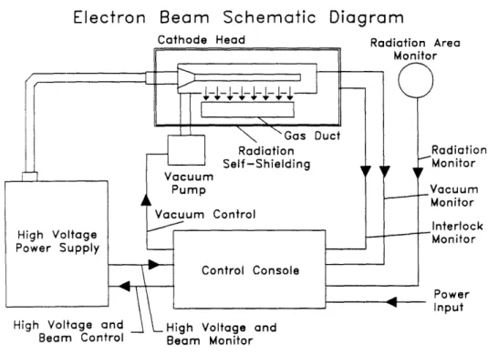
parts trays with a titanium reaction chamber, titanium ductwork, and new lead shielding to
cover the duct (see Figure 32 and Figure 33). The author performed the second
modification, discussed below.
Electron Beam Schematic Diagram
Cathode Head Radiation Area
I
Beam Control Beam Monftor
Note: F r adapted from ESI
CB 50 1510 L Electrocurtain System
Operations and Maintenance Manual
Figure 33: Electron beam schematic diagrarn.[7 I
ESI designed the CB 150 primarily for use in laboratory prototype testing, for
quality control of larger processes, and for small pilot plant operations. The operator is
given only manually-operated dials and switches to control the available beam parameters,
including the acceleration voltage, the beam current, and the cathode filament power. In
order to ready this beam for automatic control, computer-interfaced replicas of all the
variable transformers in parallel with the existing manually-actuated transformers. For
measurement of the beam voltage and current, this meant installing viewing resistors with
4-20 mA transmitters in series with the existing panel meters. This second alteration was
conceived and performed by the author with consultation from Paul Thomas, Technical
Supervisor at the PFC.
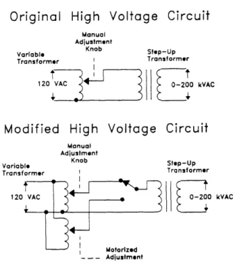
Figure 34 shows the part of the original transformer circuit and part of the new
circuit, using the beam high voltage (VAT3 on the CB 150 circuit diagram) as an example
of the changes made. Output from the variable transformer, adjustable approximately from
zero to 120 VAC, is fed to a step-up transformer in the high voltage power supply
assembly. The step-up transformer produces the useful 150 to 175 kV acceleration voltage
that drives the beam. Addition of a motor-actuated variable
Original High Voltage Circuit
Manual Adjustment
Variable Knob Step-Up Transformer I Transformer
120 VAC 0-200 kVAC
Modified High Voltage Circuit
Manual Adjustment
Variable Knob Step-Up Transformer I Transformer
120 kVAC
- - - AU31MOMT
transformer in parallel with the original transformer, along with a switch to select which
transformer is used, allows for motorized control of the acceleration voltage. In reality,
the selector switch is a heavy-duty electromechanical relay, since the circuit must carry a
maximum current of nearly 20 A at 120 VAC. The drive motor requires 120 VAC input
and a pair of switches or relays to produce either clockwise or counterclockwise rotation
of the variable transformer. The discrete, binary action of opening and closing switches is
an easy task for just about any computer.
Two of the front panels were removed from the CB 150 and replaced with two
new panels, one to accommodate the three additional variable transformers and another to
accommodate a switch network. As a safety precaution, a lock-out circuit was employed
to ensure that a change in the selection of transformers -- manual to motorized or vice
versa -- could not be made while the beam is turned on. Also, although motor switching
was made available for control computer, additional selector switches wired in parallel
retain adjustability at the front-panel. Indicator lights and motor shaft position pointers
annunciate the status of manual-versus-motorized control and variable transformer angular
position.
Computerized adjustment of beam parameters is quite important, but equally
important is the computerized measurement of parameter values. To accomplish this, the
author installed viewing resistors in series with the existing beam voltage and beam current
through the meters flow through the added viewing resistors, and the resulting voltage
drop (on the order of one volt) gives a proportional representation of the beam voltage
and current. The viewing resistor voltages are sensed by two 420 mA current loop
transmitters, which then transmit a noise-resistant current signal to the computer.
As a measure of redundancy, angular position potentiometers were mounted by the
author on the motor-driven variable transformers. Each motor shaft drives a gear train
which simultaneously turns the variable transformer shaft and a potentiometer shaft.
Potentiometer voltage outputs ranging from around two to four volts give a representation
of transformer angular position. When the beam functions properly, a one-to-one mapping
exists between the beam parameter values and their corresponding position values. If the
corresponding values deviate from their mapping beyond an acceptable range, then there is
a strong indication that the beam is running improperly. If the deviation is slight, the
computer annunciates an eror on the monitor; if the deviation is huge, the computer shuts
the system down until the offending eror is diagnosed and righted.
3.3 Plasma Reactor Dimensions/Air Stream Parameters
Physically, the plasma reactor is an approximately one inch length cross section of a six
inch by one inch titanium duct. A 25 ptm-thick titanium foil window separates the
irradiated atmospheric air stream from the evacuated space where the electrons are
generated and accelerated. A hole in the top reactor wall cut to the same area as the foil
slowing-down distance, called the range, of a 175 keV electron in air is about 30 cm,
whereas the range of a 175 keV electron in titanium is about 75 tm.[8 ] Accurate
modeling of the electron slowing-down cascade requires a more sophisticated analysis, but
these rough numbers indicate where most of the beam power is deposited: in the first
millimeter-thick skin of the back reactor wall.
Thus the small depth of the reactor, one linear inch, ensures a stiff, uniform
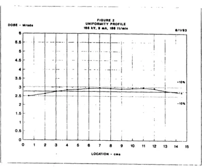
radiation profile across the reactor. The spatial shape of the absorbed dose profile,
however, depends on the shapes of both the radiation profile and the flow velocity profile.
To keep scaling of reactor capacity independent of reactor volume, these profiles must be
kept as flat as possible. Plots of radiation profile (see Figure 35), measured by ESL and
flow velocity profile (see Figure 36), measured by the author using a heated-thermistor
anemometer, verify flat profile shapes for this particular beam and duct combination.
Power deposition efficiency was sacrificed to ensure dose uniformity, but the flat shapes of
these plots indicate that first-order approximated scalings to larger units can be done
independent of reactor shape or volume. Extensive modeling of the dose penetration
profile with a Monte Carlo-type analysis was beyond the scope of this work, but such an
analysis will be performed to improve reactor shape and depth and thus ensure high power
- I I i
L_,__L
...-... ... ... . ... .... ... I i I -10% I . ; I I I II. I I I . LOCATION - .. mr -Son Cylinder I 2IM931 ffw: 5pm i F I I aCalibrated DatoiI I i :I-- Baseline Subtraced
Data i i FIGURE I .. I,.RMIT , ROME ,SG "". 9 A, 196 W.I. DOSE - MI.d. 6/1/93 - -
J ___
... I 6 5.5 -5I 4.6 4 3.5 3 2.5 2 1.51 0.5 0 C i - -I . . i 1 ! -- -;- 1 1 -I I - I- i , 1 1 --- I.-!
i , . I .,as ... ( ... ... -1 2 3 4 6 a 7 8 9 10 11 12 13 14 15Velocity Profile: Field Unit Duct
JE 0 0 M 0 U_ ID 9 0
'i
M Cr LU -2 0 2 4 6Lateral Position at Midplane [in] 8
Figure 35: Electron beam irradiation uniformity profile.[9 I
Although the operating air volumetric flow rate will depend on the inlet
concentration, the design flow rate covers a range from two to ten cubic feet per minute.
The wetted perimeter of the reactor is fourteen inches, and therefore the Reynolds
numbers which describe air flow through the reactor range from 80 to 800. Flow is in the
transition regime, which, although not fast enough to go fully turbulent, does exhibit a
nearly flat velocity profile across the width of the ducL For the given design flow rate
range, reactor residence times range from 20 to 100 milliseconds. Residence time for the
entire system ranges from approximately 200 milliseconds to two seconds. For similar
destruction efficiencies, remediation technologies with short residence times are desirable
to expedite site cleanup.
At a stable operating point, volume flow rate remains fairly constant. However, air
mass flow rate can be adjusted by throttling the flow with a pair of restrictor valves,
specifically motor-actuated butterfly valves. In the system, there are two blowers in series,
one at the dryer inlet and one at the scrubber outlet, and the design flow rate is well below
the nominal flow rates of both of these blowers. Even though this configuration provides
the over-capacity to process high flow rates of very low concentration VCs, at higher
concentrations where low flow rates are a necessity, the blowers fight the flow restrictions
and each other. Although the throttled configuration results in greater stress on the
blowers and lower pumping efficiency, the net power loss is negligible in comparison with
the rate of beam power consumption. 'Me throttled configuration also allows for
measure be kept slightly below atmospheric pressure to prohibit gas leaking out from
4. On-line Gas Composition Analysis and Feedback Control
The ability to measure the constituent compounds in the initial inlet and final exhaust air
streams is critical for characterizing process performance. In addition, confident
measurements of species concentrations can be used to establish adaptive control of the
plasma decomposition system. Mis chapter covers the operation and use of an infrared
gas composition analyzer and work done by the author towards employing this analyzer in
closed-loop algorithms for controlling the plasma reactor system.
4.1 Experience with Gas Analysis
In our lab experiments, a gas chromatograph and a mass spectrometer, specifically the
Hewlett Packard 5890 Series II Gas Chromatograph, Hewlett-Packard, Wilmington, DE,
and the Hewlett Packard 5971A Mass Selective Detector, Hewlett-Packard, Palo Alto,
tetrachloride ecomposition, these analyses yield evidence of phosgene as an inten-nediate
by-product, and chlorine gas, hydrochloric acid, carbon dioxide, and carbon monoxide as
the only stable byproducts. For trichloroethylene decomposition, dichloroacetyl chloride is
an intermediate by-product in addition to the same set of by-products as for carbon
tetrachloride decomposition.
Incorporation of a high-quality analytical chemistry instrument into the field-scale
electron beam reactor system is necessary not only for adequate waste stream
characterization and byproduct identification, but more importantly for this work to
provide a means for feedback control of important physical and chemical variables. The
compositional monitor selected for use in the field system is the Diamond 20 Fourier
Transform Infrared ("FTIR") Analyzer manufactured by KVB/Analect, Irvine, CA. In
addition to the Diamond 20 analyzer, a Bruel & Kjaer 1302 Multi-gas Monitor infrared
absorption analyzer will be used as a backup, redundant measurement of final exhaust.
Performance aspects common to the FITR and other established analysis technologies are
briefly reviewed in the following section.
4.2 Compositional Monitor Performance Criteria
Many types of compositional monitors are readily available on the market, and
improvements to those instruments are continually sought by both the device vendors and
end-users. Although many measurement applications have special requirements, for the
dominate the arket. The few most prevalent technologies include gas chromatography,
mass spectrometry, infrared spectrometry, ultra-violet/visible spectrometry, and x-ray
activation spectrometry. There are also many subordinate branches within each of these
categories, each a specialization of the parent technology geared towards particular
physical and chemical conditions.
For applicable measurement conditions, every compositional analyzer must be able
to identify and quantify chemical components in the sample under investigation. Design
criteria for which any such analyzer is constructed include:
• calibration accuracy: agreement between accepted standards and model values (i.e. from interpolation, curve fitting, etc.) which then predict measured values • measurement accuracy: agreement between accepted standards and measured
values
•
measurement precision: measure of repeatability of measurement values for
identical sample composition and conditions
• resolution: measure of minimum detectable difference between measured
compositions
• dynamic range: range of measured variable over which measurement accuracy remains acceptable
• detection limit: lowest measurable quantity with sufficient measurement
accuracy; bottom end of dynamic range
• saturation limit: highest measurable quantity with sufficient measurement accuracy; upper end of dynamic range
•
robustness: ability to tolerate all types of compounds without substantial
deterioration
• repeat rate: measure of minimum time necessary between successive
measurements
• calibration stability: measure of maximum time allowed between calibrations
without unacceptable degradation of calibration accuracy
• cost: capital cost of system, service charges, maintenance costs, training and configuration time
In our experience, the GC/MS arrangement provided excellent calibration and
measurement accuracy, precision, and resolution, yet proved disappointing in issues of
cost, robustness, reliability, configuration time and effort, and, especially for the MS,
calibration stability and robustness. Although the GC/MS configuration is the official US
EPA standard for quantitative analysis of chlorinated hydrocarbons, the KVB/Analect
FTIR was selected in place of a GC/MS system in hopes of gaining improved simplicity of
operation, faster repeat rates, lower capital and operating costs, and a recalibration period
on the order of six to twelve months instead of six to twelve days.
4.3 Gas Analysis by Fourier Transform Infrared Spectrometry
The three components of the KVB/Analect FIR system include the infrared spectrometer
with gas analysis cell, a gas sampling manifold and a data analysis computer.
An infrared spectrometer is an analytical instrument that passes IR radiation
through a substance and measures its absorbance. Because each substance has a
substance can be qualitated or identified. And because the amount of the substance is
proportional to the amount of absorbance, the substance can also be quantitated.
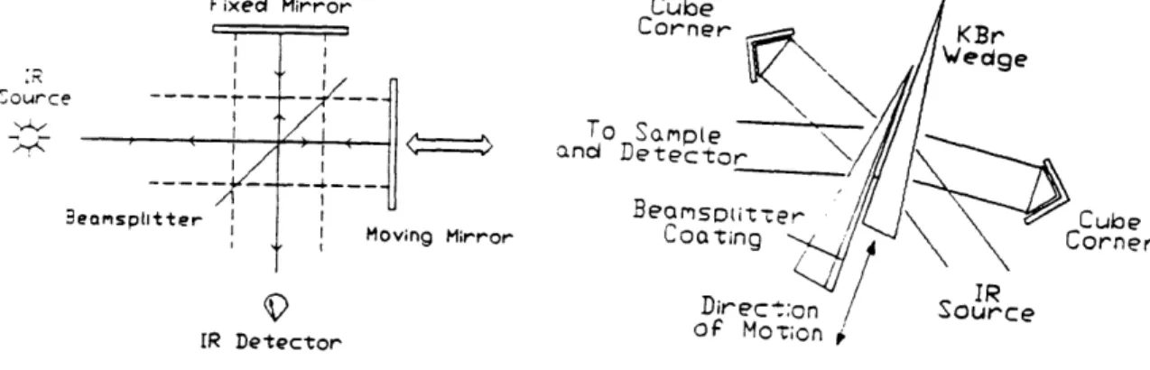
The spectrometer components include an interferometer a gas analysis cell, and an
IR detector. The historical Michelson interferometer is comprised of an IR source, a fixed
beam splitter, an IR detector, and two mirrors, one fixed and one moving. KVB/Analect's
Transept interferometer includes the IR source and detector, but substitutes two fixed
comer cube mirrors and a sliding-wedge beam splitter for the other three components.
This fixed-mirror arrangement provides for great stability against misalignment of the IR
beam and consequently allows for recalibration periods on the order of six to twelve
months.
A Simple Michelson nterferometer
The Transept Interferometer
Fixecl Mirror ___ __T__I - ; __ I + __ <: I eamsplitter I II I I Moving Mirror I 11 I :R ource To and 3 -Culoe
,orner
IR DetectorFigure 41 A simple Michelson interferometer and the KVB/Analect Transept
Although a detailed description of the operation of the interferometer is beyond the
scope of this work, a brief description is necessary to understand how the instrument
functions. The basic unit of information produced by the interferometer by a single
traverse of the bearn-splitter is called the scan. A scan produces a temporal interference
pattern detected by the IR detector as changing transmittance (or absorbance) levels.
Since the IR source is broad-band, information from an transmitted wavelengths
contributes simultaneously to the detector signal -- or interferogram -- in the time domain.
Information concerning each individual wavelength is extracted by Fourier transforming
the interferogram into the frequency domain. The transformed interferograrn. is called the
spectrum, and the IR spectrum for any given substance is a "finger-print" for that
substance. A single scan takes less than one second, yet accuracy and resolution improve
through averaging many scans and therefore result in slower repeat rates. For two
wavenumber IR absorbance resolution (equivalent to about I ppm concentration
resolution), repeat rate is about sixty seconds.
The spectrometer operates in conjunction with the sampling manifold and the data
analysis computer. The sampling manifold controls which gas streams are sampled in what
order. The data analysis computer runs a suite of software programs that perform different
mathematical and graphical display operations on the raw scan data to produce useful
composition information. The first operation is the Fourier transform of the interferogram.
to produce the raw spectrum. To improve accuracy, the computer averages several scans
of the same sample into a mean spectrum. The mean spectrum is ratioed against a
baseline-subtracted spectrum are compared with peaks collected in a matrix of calibration
spectra generated from standards of known composition and concentration. If the peaks
from an unknown composition occur at the same wavelengths as for a calibration
standard, then (barring interferences from other substances) the computer identifies the
unknown substance. The computer then calculates the concentration value for the
identified substance from the ratio of peak areas.
4.4 Adaptive Control
Often compositional monitors are used strictly as monitors. Scientists or engineers use the
output from such detectors either to gather scientific data or to ensure process quality.
Changes made to the system under observation are performed after a human observer
recognizes a need for system change, makes a decision to change the system, and finally
intervenes to alter available system parameters. Although this essentially provides for
system feedback, human intervention is required for the loop to complete. This control
action is called an open feedback loop. If the operator fails to respond to system
disturbances, then the system may not operate in its intended manner. For continuous-duty
systems, such as a field-operated rernediation system, a closed feedback loop is preferable.
In a closed feedback loop, either electrical circuitry or computer intervention provides the
path whereby on-line information can be used to automatically manipulate the system
parameters. The faster the feedback loop executes, the faster a system can respond to and
correct for disturbances or setpoint changes.
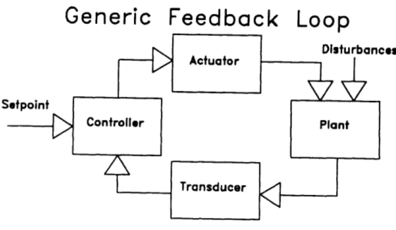
Simple feedback systems employ limit cycle operation to control the plant, a
real-world physical quantity and usually represented by a single mathematical variable. The
quintessential control example is a thermostat. In this case, the plant consists of a
space-heated or air conditioned room, and the physical variable of interest is the temperature. In
generic limit cycle systems, a setpoint, usually with upper and lower alarm limits,
determines the desired operating point, and a measurement transducer determines the
actual value of the physical variable. If due to external disturbances the physical variable
drifts beyond either alarm point due to some disturbance, an actuator provides a means to
correct the drift until the alarm point is again satisfied.
Generic Feedback Loop
Figure 42: Diagram of a simple, generic feedback loop.
In the thermostat example, if a thermostat is set to 70' degrees, the alarm points
are probably 68' and 72' degrees. If the measured temperature falls below 68', then the
heater turns on until the temperature rises to 70'. If the temperature rises above 72', then
Those which respond to a continuously-varying setpoint are known as follow-up systems.
Since the inlet concentration of the plasma reactor changes over time, the adaptive control
sequence for the plasma remediation system is categorized as a follow-up, limit-cycle
control algorithm.
Although limit cycle or "bang-bang" control is fairly easy and usually quite
inexpensive to implement, control erors may sometimes occur. If the heater turns on at
68' but the temperature overshoots beyond 70', the temperature may oscillate between
68' and say 7 V and never actually settle right at 700. This is known as chattering. If the
heater turns on at 68' and overshoots beyond 72', then the air conditioner will turn on to
force the temperature back down, and the temperature will violently oscillate back and
forth beyond the comfortable range. This is known as hunting. Chattering and hunting may
be unacceptable for sensitive control processes where either the required alarm limit
window is very small, wide oscillations are strictly forbidden, or setpoints may change
very rapidly. If any of these conditions are necessary, then a more sophisticated control
mode must be employed. Common control laws for different plants employ both linear and
non-linear models. For systems with many variables, combinations of these modes may be
used as in feedforward or cascaded control, and complex systems require advanced
control schemes, such as neural networks, artificial intelligence, state-space models, or
other expert system configurations.
provided the feedback loop executes substantially faster than disturbances in the system
may occur. The inlet concentration of the soil vapor-extraction waste stream is expected
to fluctuate due to:
• barometric pressure changes
• diurnal and seasonal temperature changes
•
long-term depression of local concentration as more contaminant is removed from
the soil, and
• possibly high concentration puffs as air pockets open up.
These changes occur on time spans of minutes to months. Although the speed of control
loop execution depends on the how fast the control computer microprocessor can run, the
speed at which setpoints are updated is limited by the repeat rate of the TIR. As with any
instrument that averages input data, there is a tradeoff between measurement accuracy and
measurement repeat rate, since high accuracy usually requires many scans to ensure
adequate averaging statistics. Accordingly, the control loop executes several times per
second, but the setpoints generated by the FTIR concentration measurements are updated
only about every two minutes. Due to the sluggish nature of the concentration changes
listed above, the two-minute update time is not anticipated to cause a loss in performance
efficiency.
and an additional software package written by KVB/Analect specifically for continuous
process measurement. The process monitoring software controls the sampling manifold,
reads raw data from the interferometer, and calculates concentration information using the
calibration matrix, all with about a two minute repetition period. Concentration
information for each compound of interest is output from the data analysis computer serial
port in the form of ASCII text files. These files must be read by the supervisory computer
and the concentration data must be converted into meaningful setpoint information.
Control sequences relying on the strong correlation between concentration information,
contaminant destruction, and absorbed dose are covered in the following section.
4.5 Dose Mapping Control Sequence
The fundamental quantity used in describing the effects of ionizing radiation is the
absorbed dose. Ionizing radiation exists in many forms, including X-rays, gamma rays, and
accelerated particles, such as electrons, protons, neutrons, and heavy ions. The absorbed
dose related to each of these forms of radiation quantifies the energy absorbed per unit
mass of matter contained in the exposed target. For moderate energy radiation (below
I WV), the incident particles or electromagnetic photons knock bound electrons from
stable molecular or atomic orbits. Often these freed electrons are energetic enough to
knock yet additional electrons free from other molecules or atoms. Deexcitation of atoms
with recently-removed or freshly-recaptured electrons results in reradiation of X-ray,
ultraviolet, and optical wavelength electromagnetic energy. Thus the end result for all the
different sources of radiation is an electron/photon cascade.
Although the dose required to generate one electron-ion pair in air is on the order
of 35 eV, several systems of units are commonly used for describing the doses absorbed
by targets of larger mass. The Systeme Internationale/MKS derived unit of absorbed dose
is the Gray ("Gy"). It is equivalent to the absorbed dose when the energy per unit mass
imparted to matter by ionizing radiation is one joule per kilogram. Equivalent labels for the
same quantity but used by different radiological fields include the specific energy imparted,
the kerma, and the absorbed dose index. Another unit is the rad, for which one Gray
equals one hundred rads. Equivalently, ten kGy (or kilojoules per kilogram) equals one
Mrad. The absorbed dose rate is the energy per unit mass imparted to matter per unit time,
or equivalently the specific power imparted. Therefore, the time integral of the absorbed
dose rate equals the absorbed dose.
In the case the electron beam-based plasma reactor, the variables that contribute to
the absorbed dose include the beam acceleration voltage, the beam current, and the mass
flow rate of the air stream under irradiation. For a specified inlet contaminant
concentration, destruction improves with increasing absorbed dose. However, destruction
also improves with decreasing initial inlet concentration for a specified dose. These trends
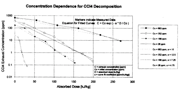
An approximate functional form for carbon tetrachloride destruction determined from the
empirical data shown earlier is given as follows, where Co is the initial contaminant
concentration, C the final concentration, D the absorbed dose, and a a positive coefficient
with units ppnVkGy:
C = Co exp(- aD
Equation 41
Co
Absorbed dose is the power deposited,
Pd,per unit mass flow rate, Q. The power
deposition is the product of the acceleration voltage, V, the beam current, I, and the power
deposition efficiency,
Pd V I
D
Equation 42
Q
Q
Curve fitting the data shows with fair agreement that for each given inlet concentration,
exhaust concentration falls off nearly exponentially with increasing energy deposition. See
Figure 43: Curve
An exponential-approximation destruction model is drawn from such curves.
Fitting each string of data points to an exponential function with C, Co, and
Daknown, we
Markem ind D
quation1for Fitted Curv MC"= "Cosedxp a D Co
C exh&M ban] Co-kWW--MV0on[PPMJ
0:
Concentration Dependence for CC14 Decomposition
low