Analysis, Fabrication and Testing of a
MEMS-based Micropropulsion System
by
Robert L. Bayt
FDRL TR 99-1
Fluid Dynamics Research Laboratory
Department of Aeronautics and Astronautics
Massachusetts Institue of Technology
Cambridge, MA 02139
Abstract
Various trends in the spacecraft industry are driving the development of low-thrust propulsion systems. These may be needed for fine attitude control, or to reduce the mass of the propulsion system through the use of small lightweight components. The nozzle converts the stored energy in a pressurized gas into kinetic energy through an expansion. The nozzle efficiency is characterized by the amount of kinetic energy leaving the nozzle, and is governed by the exit velocity. Because of the increase in viscous losses as scale is reduced, it was feared that high Mach number supersonic flows could not be generated in microdevices. However, a scaling analysis indicates that the reduction in throat area can be offset by an increase in operating pressure to maintain a constant Reynolds number. Therefore, thrust can be decreased by reducing the nozzle scale, and viscous losses mitigated by running at higher chamber pressures.
In order to operate a supersonic nozzle efficiently, the geometry must be contoured to guard against flow separation and reduce the boundary layer thickness at the throat. Deep Reactive Ion Etching enables extruded flow channels of arbitrary in-plane geometry to be created at scales an order of magnitude smaller than conventional machining. These channels are encapsulated by anodically bonding glass to the upper and lower surfaces. Testing indicates that 11.3 milliNewtons of thrust is generated for a nozzle with a 37 micron throat width, 308 microns deep, and a 16.9:1 expansion ratio. The exit velocity was 650 m/s, which corresponds to an exit Mach number of 4.2, and an Ispof 66 seconds. This is 100 m/s higher than previously
achieved in a micromachined device and demonstrates that supersonic flows can be generated at this scale. The performance of the system is increased by electrothermal augmentation. By resistively heating fins present in the chamber, a thruster temperature of 700◦C has been achieved. This will increase the theoretical Isp to 145 seconds. However, the reduction in Reynolds number with increased chamber temperature causes
viscous dissipation to increase and thruster efficiencies to decline. The efficiencies vary with Reynolds number in the same fashion as their unheated counterparts, which confirms that Reynolds number is the governing similarity parameter. The thruster was operated at a temperature of 420◦C, and demonstrated an Ispof 83
seconds. This represents an Isp efficiency of 79% for an 8.25:1 area ratio nozzle. These results suggest that
MEMS-based micropropulsion systems offer higher performance at lower mass, when operated at Reynolds numbers above 2500 for both heated and unheated thrusters.
This report is the Ph.D. Thesis of Robert Bayt, Submitted to the Department of Aeronautics and Astro-nautics, M.I.T. in June, 1999, Supervised by Prof. Kenneth Breuer. For more information, contact, Prof. K. Breuer: [email protected]
Acknowledgments
It has been remarked that I have set the record for affiliation with the most research groups at MIT. This is primarily due to the diverse nature of Microelectromechanical systems. Without consultation from all of the relevant experts, it would be difficult for microsystems to be developed. This thesis has only been possible, because each of the members of these groups has answered a question of mine over the past four years, and its completion is a tribute to them. These labs are: the Microsystem Technology Lab, particularly the members of the Schmidt Group, the Fluid Dynamics Research Lab, the Space System Lab, the Gas Turbine Lab, and the Active Materials and Structures Lab.
My sincerest thanks go to the members of my committee who were always up to speed on my work, and offered perfect guidance along the way. This is especially true for my advisor, Kenny Breuer. He is a testament to the MIT work ethic, and embodies the inquisitive nature needed in a research environment. I am proud to call him a mentor and a friend. Similarly, Marty Schmidt and Manuel Martinez-Sanchez have inspired me to pursue problems in their respective fields, MEMS and advanced propulsion technologies.
This work was only possible through the financial support of the Graduate Student Researchers Program at Goddard Spaceflight Center. This was originally administered by Dr. Gerald Soffen, who motivated me to attend MIT, and has always provided sound advice for my career. Dennis Asato was the center technical advisor, and has shown nothing but enthusiasm for this work. In addition, the Microdevices Lab at the Jet Propulsion Laboratory provided the initial funding to begin the research into MEMS-based propulsion through contract 960444 monitored by Bill Tang. Finally, the Air Force Office of Scientific Research has provided the necessary funds to allow the completion of this work through under contract #F4920-97-1-0526 monitored by Dr. Thomas Beutner.
This work was an outgrowth of a preliminary study performed by Adam London, and is referenced frequently throughout this thesis. In addition to being a predecessor, Adam has been a friend and confidant that always knew how to look at the big picture a little differently. Newton said he could see farther than others because he stood on the shoulders of giants. Too me, Adam is a giant.
Dr. Arturo Ayon has been the research force behind the deep reactive ion etcher, and has brought this technology to the performance levels we are enjoying today. He has taught me nearly everything I know about microfabrication technology. In addition, he has shown me the true meaning of simpatico (as well as Chianti!). In this same vain, Kurt Broderick has shown me so many tricks and nuances of the Technology Research laboratory, he has probably cut six months from my development time. All of the members of the Schmidt group provided insight and advice in fabrication. Not only that, they are a fun group to know. Thanks to Joel, Samara, Reza, CC, Jo-ey, Becky, Zony, and Christine.
The computational work presented here was based on a prior code written by Ed Piekos. It was such a fine work before I got my hands on it. I turned his ’99 ’Vette into a ’76 Gremlin. But, my thanks to him, Ali Merchant, and Tolulope Okasanya for their insight into CFD, and to really opening my eyes to the computational world.
The experimental work could not have been complete without the thrust results. These were made possible by the father of MEMS-based propulsion, Siegfried Janson and his colleagues at the Aerospace Corporation. In addition, I would not be done with out the help of Vadim Khayms, who was my quals buddy as well as the builder of the MIT test stand. His assistance in making the final measurements was invaluable.
The students of the Gas Turbine lab, particularly Amit Mehra and Luc Frechette, were instrumental in the design of the heater, as well as, the side projects involving FLUENT modeling. Their friendship, as well as Amit’s supply of fine Cigars and Cognac, added to the enjoyment of this work.
In addition to the technical support, this work would not have been possible without the enduring love and prayers I have received from home. My wife, Heather, has been my continual source of inspiration. She was genuinely interested in my work, and has always held my goals as her goals. Her strength has grown through these tests, and she is now ready to take on the challenges of motherhood, for which she is ideal.
My family has always believed in me, and it is because of them I achieved my highest goal. It is now because of them I will try to raise the bar one notch higher. My father has been the perfect role model, exemplifying honesty, integrity and strength. My mother has always embodied the spirit and strength to make sense of everyday life. My brother, David, is my source of pride, for he is beginning to spread his wings,
and set his sights toward building a better world. In addition, my In-Laws have always held an interest in my work, and have been very supportive throughout. Thank you to Ron, Suzanne, Debra, Todd and Lynda. Having been at MIT for so long, I have had many officemates that have enjoyed the excitement and doldrums of each day. Thanks to Tim, Cyrus, Eugene, Karsten, and Chris Protz.
Boston has truly been a better place because of my friends Aaron, Ann, John R., Margee, Alex, Maggie, Kamyar, Mitch, Homero, Jake, John H., Kevin, Suzanne, Paulo, Marcella, James, Tatsuo, Darrel, Karen, Greg2, Angie, Alex B. and Ashok. My late night ramblings with my friend D.J. Orr have really helped me put a lot of the engineering world into perspective. My lunches and outings with my good friend, Robin Smith, provided me with a reality check not always found in the corridors of MIT.
Last, and above all, I must give my thanks to God, from whom all blessing flow. It has only been through faith that I have known which direction to travel. May my future endeavors always be a testament to His glory.
When I left Indiana, people asked me why I wanted to go to Boston. My response was, “I have always wanted to go to MIT” It has only been because of these people, and not the brick and mortar on this fine piece of real estate, that made this the right choice.
Contents
Acknowledgements 3
1 Introduction 15
1.1 The Role of Microspacecraft . . . 15
1.2 The Role of Micropropulsion . . . 15
1.2.1 Propulsion Architectures . . . 16
1.3 Motivation for a Microfabricated Pressurized Propulsion System . . . 17
1.4 Previous Micronozzle Investigations . . . 18
1.5 Objectives . . . 19
1.6 Contributions . . . 20
1.7 Summary . . . 21
2 Scaling Analysis and the Baseline Microthruster 23 2.1 Direct Effects of a Reduction in Scale . . . 23
2.2 Indirect Effects - Performance Variability with Scale . . . 23
2.3 Performance Trade-offs with Design . . . 24
2.4 Thruster B aseline . . . 25
2.4.1 Thruster Requirements . . . 25
2.4.2 Thruster Scale Limitations . . . 25
2.4.3 Baseline Geometry Specifications and Operating Conditions . . . 26
3 Numerical Analysis of Micronozzle Performance 27 3.1 Analysis Objective . . . 27
3.2 Assumptions of the Numerical Analysis . . . 27
3.3 Finite Volume Formulation . . . 28
3.3.1 Spatial Discretization . . . 29
3.3.2 Temporal Discretization . . . 30
3.3.3 Artificial Viscosity . . . 31
3.3.4 Boundary Conditions . . . 31
3.4 Running the Code . . . 34
3.4.1 Nozzle Terminology . . . 34
3.4.2 Grid Development . . . 34
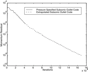
3.4.3 Solution Convergence . . . 36
3.4.4 Grid Resolution . . . 36
3.5 Flow Field Analysis . . . 36
3.6 Performance Parameters . . . 41
3.6.1 Effects of Wall Boundary Conditions on Performance . . . 44
3.7 Boundary Layer Analysis and Three-Dimensional Effects . . . 47
3.7.1 Test Case Boundary Layers: Determining Effective Area Ratio . . . 47
3.7.2 Evaluation of Nozzle Separation and the Laminar Flow Assumption . . . 50
3.7.3 Wall Roughness Effects . . . 52
3.8 Summary . . . 55
4 Cold-Gas Thruster Fabrication 57 4.1 Microfabrication Description . . . 57
4.1.1 Surface Micromachining . . . 57
4.1.2 B ulk Micromachining . . . 57
4.1.3 Wafer B onding . . . 59
4.2 Process Flow for Micronozzle Fabrication . . . 60
4.3 Process Analysis and Enhancement . . . 63
4.3.1 Full Geometry Etch . . . 63
4.3.2 Nested Masking . . . 64
4.3.3 Halo Masking . . . 68
4.4 Packaging . . . 70
4.4.1 Entrance Effects . . . 71
4.5 Summary . . . 73
5 Cold-Gas Thruster Testing 75 5.1 Test Set-up . . . 75
5.1.1 Mass Flow Testing . . . 75
5.1.2 Thrust Stand . . . 75
5.2 Uncertainty Analysis . . . 77
5.3 Test Results . . . 78
5.3.1 Mass Flow Test Results . . . 78
5.3.2 Thrust Test Results . . . 79
5.4 Comparisons between Numerical and Experimental Data . . . 81
5.5 Experimental Deviation from the Numerical Calculations . . . 87
5.5.1 Endwall Boundary Layer Blockage . . . 87
5.5.2 Nonequilibrium Effects . . . 92
5.5.3 Roughness Induced Transition . . . 92
5.5.4 Effect of Simulation Outlet Boundary Conditions . . . 93
5.6 Performance Comparison with Other Experiments and Models . . . 93
5.7 Summary . . . 95
6 Electrothermal Augmentation 97 6.1 B ackground . . . 97
6.2 Resistojet Architecture . . . 98
6.3 Heater Thermal Model . . . 100
6.3.1 Governing Equations and Correlations . . . 100
6.3.2 Electrical Model . . . 103 6.3.3 Design Studies . . . 106 6.3.4 Parasitic losses . . . 110 6.4 Resistojet Fabrication . . . 111 6.5 Resistojet Testing . . . 115 6.5.1 Electrical Tests . . . 115
6.5.2 Vacuum Chamber Thrust Tests . . . 118
6.5.3 Thrust Test Results . . . 119
6.5.4 Overall Heated Thruster Assessment . . . 124
6.6 Summary . . . 127
7 Conclusions and Recommendations 129 7.1 Impact on Propulsion Technologies . . . 129
A Non-Dimensionalization 131
B Code Listing 133
List of Figures
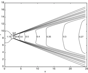
1.1 Domains of applicability of various propulsion architectures. This shows which architectures minimize mass and power consumption for a given set of mission requirements. Reproduced from London [3] . . . 17 3.1 Flux model in computational space . . . 29 3.2 Nozzle Domain . . . 32 3.3 Convergence history for a 5.4:1 nozzle with 125x160 points at a Reynolds number of 1284 . . 36 3.4 Mach Number contours for the 16.9:1 nozzle at a Reynolds number of 1914 . . . 37 3.5 Non-Dimensionalized Pressure (P ) contours for the 16.9 nozzle at a Reynolds number of 1914 38 3.6 Non-Dimensionalized Density (ρ) contours for the 16.9:1 nozzle at a Reynolds number of 1914 38 3.7 Non-Dimensionalized Temperature (T ) contours for the 16.9:1 nozzle at a Reynolds number
of 1914 . . . 39 3.8 Exit Plane Mach Profiles for the 5.4:1 Nozzle operating at various Reynolds numbers. . . 39 3.9 Exit Plane Pressure Profiles for the 5.4:1 Nozzle operating at various Reynolds numbers . . . 40 3.10 Centerline Mach Profiles for the 5.4:1 Nozzle operating at various Reynolds numbers . . . 40 3.11 Numerical predictions of the variation in the coefficient of discharge with Reynolds number
for all geometries tested. Inlet section and throat radius of curvature is identical for cases. Therefor all values are nearly identical. . . 42 3.12 Numerical predictions of the variation in the Isp efficiency with Reynolds number for all
geometries tested . . . 43 3.13 Numerical predictions of the variation in the thrust efficiency with Reynolds number for all
geometries tested . . . 43 3.14 Numerical predictions of the variation in the thrust coefficient with Reynolds number for all
geometries tested. The highest expansion ratios have the highest Cf, as expected. . . 44
3.15 Exit plane Mach profiles for the 5.4:1 nozzle at a Reynolds number of 1578. The variation between the solutions is minimal and accounts for less than 0.5% of the thrust. . . . 45 3.16 Exit plane Mach profiles for the 5.4:1 nozzle at a Reynolds number of 887 . . . 45 3.17 Knudsen number contours for the 5.4:1 nozzle at a Reynolds number of 1578 . . . 46 3.18 Knudsen number contours for the 5.4:1 nozzle at a Reynolds number of 887. The contours
verify that slip velocity is not dominant because Kn < 0.03. . . . 46 3.19 Displacement thickness growth from throat to exit along the nozzle wall for the 16.9:1 nozzle.
Distance along the nozzle wall and displacement thickness are normalized by the throat width. The boundary layer thickness increases significantly with decreasing Reynolds number. At the lowest Reynolds number, the boundary layer accounts for 38% of the exit plane. . . 48 3.20 Variation of effective area ratio with actual geometric area ratio for the 15.3:1 nozzle. The
effective area ratio is calculated by reducing the local width by the amount of the displacement thickness on both walls . . . 49 3.21 Variation of effective area ratio with actual geometric area ratio for the 16.9:1. . . 49 3.22 Thrust and Isp efficiencies are computed from numerical simulations. These are compared to
inviscid calculations of similar nozzles operating at the same effective area ratio as depicted in figure 3.21 . . . 50
3.23 Momentum thickness growth from throat to exit along the nozzle wall for the 16.9:1 nozzle. Θ is normalized by the throat width, as is distance along the nozzle wall. . . 51 3.24 ReΘ variation from throat to exit along the nozzle wall for the 16.9:1 nozzle. This is well
below the stability point for a Mach 3.8 flow of ReΘ= 300 as computed by Mack [30], for all cases. . . 51 3.25 Subsonic boundary layer growth from throat to exit for various expansion ratios and operating
conditions. . . 53 3.26 Thrust efficiency variation with Reynolds number for different nozzle divergence angles. Notice
that the higher angles perform better at low Reynolds numbers. . . 53 3.27 Displacement thickness as a fraction of the nozzle local area along the nozzle. . . 54 4.1 Example of anisotropic etching of silicon with KOH using oxide as a masking material. This
results in square nozzles with at 32.5 degree divergence. Notice the sharp corners at the throat. [34] . . . 58 4.2 Gas flow cycles during plasma etching. Overlaps occur due to finite response times of flow
controllers [36] . . . 59 4.3 Micrograph view of an anisotropic etch (left) and the scalloping observed on the walls due to
the periodic etch/deposition[36] . . . 59 4.4 Cross-section of the silicon device wafer at key points in the fabrication process. a) begin with
a clean < 100 > silicon wafer b) coat in photoresist and pattern through exposure through features in a mask c) DRIE through nozzle feature d) Strip resist and anodically bond to glass 61 4.5 SEM of the nozzle exhaust cavity. Nozzle exit plane is small opening centered in the cavity. 62 4.6 Arrangement of individual nozzles in a die. Six discharge to the environment, and the three
in the center discharge into an on-chip cavity for benchtop testing. . . 63 4.7 Variability of etch rate with feature size for different etch recipes [36]. This reduction in etch
rate is termed the loading-effect. The recipe number corresponds to a proprietary combination of etch parameters documented by MIT. . . 64 4.8 SEM of the nozzle-plenum system etched simultaneously for two different nozzle geometries . 65 4.9 Close-up of a similar nozzle throat to that in figure 4.8 . . . 65 4.10 SEM of a bell nozzle exit plane, etched to 250 microns. Notice the smooth walls as well as
the anisotropy. . . 66 4.11 An example of overetching which occurs when a nested mask is not properly timed . . . 66 4.12 Poor feature interface due to nested feature not clearing properly . . . 67 4.13 5.4:1 nozzle with a 19 micron throat created using a halo mask. The depth of all nozzles in
this section was 308 microns. . . 69 4.14 a) 7:1 nozzle with a 34 micron throat b) 15.3:1 nozzle with a 18 micron throat. Both were
created using a halo mask . . . 69 4.15 Packaging solution for the micronozzle study. Pre-drilled hole in die is clamped to an o-ring
in a gas-injection manifold. . . 70 4.16 Streamlines in xz-plane of nozzle chamber at a Re = 1450. A 2-D simulation with F LU EN T
is used to compute the flow field. . . 72 4.17 Reattachment point of separation bubble downstream of injection inlet (distance normalized
by channel height). This is the point the flow returns to nearly axial. . . 72 5.1 Mass Flow Test Assembly. The gas flow through the nozzle is discharged into a bell jar
evacuated to 1 torr. This allows mass flow through the overexpanded nozzle to be measured. 76 5.2 Thrust Stand Schematic. The thrust against a restoring spring allows the displacement to be
measured, and the subsequent thrust to be evaluated. Weights of known mass hanging from the pulley provide a calibration thrust to the stand. . . 76 5.3 Mass flow measurements for 3 nozzles of 5.4:1 area ratio and 20 micron throats. Variation of
results is minimal because the geometric variation in manufactured nozzles is minimal. . . 78 5.4 Deviation of mass flow in figure 5.3 from linear slope connecting origin and the maximum flow
5.5 Mass Flow variation with chamber pressure for 3 nozzle geometries. Larger throats result in
larger flow rates for the same pressure. . . 80
5.6 Thrust variation with chamber pressure for 3 nozzle geometries. Larger exit areas result in larger thrusts. . . 80
5.7 Isp variation with thrust. The dramatic reduction at low thrusts is due to the increase in viscous effects present at low chamber pressures, and hence low thrusts. . . 81
5.8 Mass flow efficiency (Cd) variation with Reynolds number for the 7.1:1 geometry. The Cd compares well with the experiment for all but the lowest Reynolds numbers. This is where the boundary layers are the thickest. . . 82
5.9 Mass flow efficiency (Cd) variation with Reynolds number for the 15.3:1 geometry . . . 82
5.10 Mass flow efficiency (Cd) variation with Reynolds number for the 16.9:1 geometry . . . 83
5.11 Thrust efficiency variation with Reynolds Number for the 7.1:1 nozzle geometry . . . 83
5.12 Thrust efficiency variation with Reynolds Number for the 15.3:1 nozzle geometry . . . 84
5.13 Thrust efficiency variation with Reynolds Number for the 16.9:1 nozzle geometry . . . 84
5.14 Isp efficiency variation with Reynolds Number for the 7.1:1 nozzle geometry . . . 85
5.15 Isp efficiency variation with Reynolds Number for the 15.3:1 nozzle geometry . . . 85
5.16 Isp efficiency variation with Reynolds Number for the 16.9:1 nozzle geometry . . . 86
5.17 Comparison of the numerical results and the experimental results of the coefficient of thrust as it varies with Reynolds number for the 16.9:1 nozzle . . . 86
5.18 Variation of the quasi-3-D effective area ratio with actual geometric area ratio. This is for a nozzle with an exit height to width aspect ratio of 0.48. . . 88
5.19 Variation of the quasi-3-D effective area ratio with the actual geometric area ratio. This is for a nozzle with an exit height to width aspect ratio of 1.14. . . 88
5.20 Variation of exit Mach number with area ratio. If operated at 300K chamber temperature, the exit velocity on the right applies . . . 89
5.21 Thrust efficiency variation with Reynolds Number for the 16.9:1 nozzle geometry. This is for a nozzle with an exit height to width aspect ratio of 0.48. . . 90
5.22 Isp efficiency variation with Reynolds Number for the 16.9:1 nozzle geometry. This is for a nozzle with an exit height to width aspect ratio of 0.48. . . 90
5.23 Thrust efficiency variation with Reynolds Number for the 15.3:1 nozzle geometry. This is for a nozzle with an exit height to width aspect ratio of 1.14. . . 91
5.24 Thrust efficiency variation with Reynolds Number for the 8.26:1 nozzle geometry. This is compared to a 2-D CFD simulation with endwall corrections. Maximum overprediction is 13% This is for a nozzle with an exit height to width aspect ratio of 1.03. . . 91
5.25 Ratio of the rotational relaxation time to the residence time at the wall of the nozzle. This computation was performed at the 3:1 area ratio in the supersonic portion of the nozzle for various Reynolds numbers based on the Belikov model described in Gochber [42] . . . 93
5.26 Isp efficiency variation with Reynolds Number for models and experiments of other investiga-tors. . . 94
6.1 Metal or polysilicon resistor defined by photolithography techniques for resistojet applications 98 6.2 a) Detail of completed resistojet etch b) bonded resistojet with packaged electrode. Current is passed through chip, and preferentially passes through fins due to large resistance around the voids. . . 99
6.3 A) An energy balance is performed on differential elements of the fin and fluid to determine equilibrium temperatures. Arrows represent heat transfer paths B) Effective Heater cross-sectional area and convective area of the full geometry are used despite this being a 1-D analysis. . . 101
6.4 Resistance variation with temperature for boron-doped silicon with a doping of 1× 10¹⁹ carriers/cc [48]. The intrinsic point occurs when the silicon carriers are dominant over the dopant acceptor carriers. This is the stable point during constant current operation. . . 104
6.5 Contours of power dissipation throughout the domain. The values are symmetric about the centerline of the fin. Non-dimensional quantities can be converted to dimensional values with equations (6.22) and 6.21. . . 105 6.6 Temperature Profiles for a heater with 5 fins 500 microns long, 100 microns wide, and a gap
of 50 microns between fins. The governing parameters are Bi = 1.09, S∗= 0.46, and St = 6.51 106 6.7 Temperature Profiles for a heater with 10 fins 125 microns long, 50 microns wide, and a gap
of 50 microns between fins. The governing parameters are Bi = 1.09, S∗= 0.46, and St = 6.51 108 6.8 Temperature Profiles for a heater with 5 fins 125 microns long, 50 microns wide, and a gap of
50 microns between fins. The governing parameters are Bi = 1.80, S∗= 2.52, and St = 6.61 . 108 6.9 Fabrication sequence of microresistojet. . . 111 6.10 First attempt at the resistojet etch. Grass in between the fins will obstruct flow, and is a
result of the nested mask . . . 113 6.11 Increased coil power during the etch, following an oxygen plasma, has eradicated the grass at
the expense of feature anisotropy . . . 114 6.12 Intermediate coil power eliminates the grass and maintains etch anisotropy . . . 114 6.13 SEMs of a) 100 micron fins with 50 micron gaps bonded to thesilicon wafer b) 50 micron fins
bonded to the silicon wafer. The bond was successful for both dimensions on all fins. No fractures were incurred. . . 115 6.14 Integrated thruster testing in vacuum chamber. Copper leads are clamped to nozzle by means
of a ceramic package. Gas is injected through a Kovar tube brazed to the manifold on one end, and attached to the silicon with a glass frit on the other. . . 116 6.15 Heater Temperature during the test at various current and dissipated power settings. The
time history plot illustrates transient behavior as well as power and current levels needed to achieve a given temperatures. . . 117 6.16 Heater temperature as a function of applied current. Once temperature has reached stability,
increases in current do not increase temperature. . . 118 6.17 View of the nozzle opening during heater operation. The thermal deformation of the leads
has caused the ceramic package to rise off of the support. This could potentially lead to frit failure. . . 119 6.18 Performance of the thruster at various thrust levels for both heated and unheated devices. As
temperature increases, thrust should remain constant and Ispwill increase. However, increases in temperature reduce the Reynolds number and cause the thrust to decrease. . . 120 6.19 Coefficient of Discharge variation with Reynolds number for heated cases in comparison to
previous experimental runs of the old nozzle design which are unheated. . . 121 6.20 Thrust Efficiency variation with Reynolds number for heated cases in comparison to previous
experimental runs of the old nozzle design which are unheated . . . 122 6.21 Isp Efficiency variation with Reynolds number for heated cases in comparison to previous
experimental runs of the old nozzle design which are unheated. This, along with figures 6.19 and 6.20, verify that Reynolds number is the governing similarity parameter. . . 122 6.22 Thrust Efficiency variation with Reynolds Number for the 8.26:1 nozzle geometry. This is
compared to a 2-D CFD simulation with endwall corrections. Maximum overprediction is 13% 123 6.23 Isp Efficiency variation with Reynolds Number for the 8.26:1 nozzle geometry. This is
com-pared to a 2-D CFD simulation with endwall corrections. The maximum overprediction is 13% . . . 123 6.24 Dissipated power for a range of thruster temperatures. The square points depict the ideal
power input for the flow to reach a given temperature . . . 125 6.25 Variation of propulsive efficiency with Reynolds for the 44 psia chamber pressure. If the lead
length is optimized for least power losses, as well the conduction into the support, the least losses curve could be achieved. . . 126 6.26 Variation of propulsive efficiency with Isp. This provides mission designers with an indication
List of Tables
3.1 Nozzle geometry test cases and operating conditions used for analysis . . . 35 3.2 Performance property variation with slip velocity incorporated for 5:41 nozzle at Re = 1578 . 44 4.1 Comparison of design nozzle geometries and the result after fabrication . . . 68 5.1 Comparison of the performance of DRIE nozzles with conventionally machined nozzles, and
KOH etched nozzles . . . 94 6.1 Fin geometry test cases and operating conditions used for analysis . . . 109
Nomenclature
Roman
¯
C Mean molecular speed
cd Coefficient of discharge
cp Coefficient of specific heat at constant pressure
D Local width
E Total Energy ρ[e +12(u2+ v2)]
F Inviscid fluxes
Ft Thrust Force
G Viscous fluxes
ho Etch depth
Isp Specific impulse
Ibit Impulse bit
Kn Knudsen number
J Moment of inertia
kw Wall thermal conductivity
˙
m Mass flow
Nd Number density
P r Prandtl Number
P Pressure
q Rate of heat loss
Re Reynolds number
T Temperature
˙
wp Propellant used
u x-component Gas velocity
Greek
∆V Orbital Velocity Change
δ∗ Displacement thickness
& Expansion Ratio
ηIsp Isp efficiency= Ispmeasured/IspIdeal
ηthrust Thrust efficiency= T hrustmeasured/T hrustIdeal
γ Ratio of specific heats
λ Mean free path
ρ Gas density
τ Shear stress
θ Momentum Thickness
θt Spacecraft pointing deadband
Subscripts
e, exit Exit plane of nozzle
edge Boundary layer edge as defined by δ99%
eng Engine f fluid i inlet o,∞ Chamber conditions s/c Spacecraft t, thr Throat location w Wall location
Acroynms
DRIE Deep Reactive Ion Etching
FEEP Field Emission Electric Propulsion JPL Jet Propulsion Laboratory
MEMS Microelectromechanical Systmes
PPT Pulsed Plasma Thruster
Chapter 1
Introduction
1.1
The Role of Microspacecraft
In this time of decreasing federal budgets, the focus of NASA, and the aerospace industry at large, is to reduce satellite life-cycle costs while still delivering a spacecraft with the capability of performing useful science or a commercial service. With their New Millennium program, the Jet Propulsion Laboratory (JPL) is developing technology for the next generation of spacecraft that will encompass all of NASA’s directives: Faster, Better, Cheaper.
A wide range of resources from program management techniques to advanced technologies are being focused on achieving each of these directives. One of the means to this end is the development of mi-crospacecraft [1]. Such a satellite may contain only one instrument, but this reduction in complexity will lower costs, by facilitating systems integration. In addition, the small sizes allows the selection of a smaller, less expensive launch vehicle, or the integration of multiple satellites per vehicle.
JPL has examined a number of mission scenarios that are conducive to miniaturization, which are de-scribed by Mueller [2]. These missions are a rendezvous with the near Earth asteroid, Vesta, a Europa orbiter, an Earth observing cluster, and a deep-space interferometer. In addition to these missions, Lon-don [3] performed a similar analysis for a future generation global positioning system, a Mars observer, and a low Earth orbit communication system. This indicates that there are a wealth of opportunities in which microspacecraft can perform useful science, while reducing cost and development time.
The aerospace community envisions Microelectromechanical systems (MEMS) as a means for attaining a high degree of functionality at a much smaller scale. MEMS technologies are sensors and actuators which are fabricated with the use of the micromachining techniques developed by the microelectronics industry. As defined by Mueller [2], first generation microspacecraft will have a mass of 20 kg, a baseline dimension of 30 cm, and consume 20 Watts of power. It will begin to integrate MEMS components over the next 5 years to demonstrate the proof-of-concept. The second generation microspacecraft (1-5 kg), will then begin to integrate large numbers of MEMS subsystems. This ultimately leads to a third generation (< 1 kg), that is a completely micromachined device with all systems integrated during fabrication. The first two generations will illuminate the feasibility issues of the third generation.
1.2
The Role of Micropropulsion
One implication of microspacecraft is that they will need small systems. Due to the limited capabilities of the early launch vehicles, the first satellites were inherently small, and due to the lack of truly miniature systems, possessed limited functionality. Explorer I (1958) was only 15 kg, and Vanguard I (1958) was only 1.5 kg. These were the first true microsatellites. As technology progressed, satellites developed pointing requirements and the need to maintain precise orbits. On-board propulsion systems were added to make-up for aerodynamic drag and solar pressure disturbances, as well as counteract gravity-well distortions due to the oblateness of the Earth. Since the satellites were still small due to the launch vehicle capacity, the first micropropulsion systems were developed. Their function was two-fold: provide slewing capability to adapt
to different pointing requirements, and maintain the attitude within a deadband (angular position limit) to meet pointing tolerances. Sutherland and Maes [4] reviewed the state-of-the-art for different propulsion architectures in 1966. They established system criteria which can be used to judge applicability of a given architecture. These are: Total Impulse, Thrust Level and Control, Life and Reliability, State of Develop-ment, Duty Cycle, EnvironDevelop-ment, Response or Impulse bit, Exhaust Products, and Cost. This lead to an establishment of the domains of applicability of for propulsion architectures, which was later revised and updated by London [3] to include new or improved technologies.
Sutherland and Maes further stress the need to generate not only low thrust, but to minimize the impulse bit (Ibit). The Ibit is the minimum impulse obtained once the thruster is given the command to fire. It is the integrated thrust over the fastest valve cycle time. Sutherland et al. show that the propellant used per thruster firing for maintaining attitude about a deadband can be computed for the undisturbed rotation of a constant mass vehicle about one axis as
˙ Wp=
l(∆Ibit)2
4J IspΘt
, (1.1)
where J is the moment of inertia, Θt is the angular position limit, and l is the moment arm. Thus, an
improvement by decreasing Ibit is more important than an improvement in increased Isp for the purpose of attitude control.
Using the JPL design reference missions as baseline requirements, this work will focus on the miniatur-ization of the on-board propulsion and the fabrication of these devices through MEMS technologies. The first generation microspacecraft design requirements are a minimum thrust of 4.65 mN for slewing, and an Ibit of 0.013 mNs for maintaining attitude [2].
1.2.1
Propulsion Architectures
With the utility of micropropulsion established, the ideal architecture for meeting the requirements should be assessed.While Sutherland and Maes reviewed the current state-of-the-art for 1966, that has been updated by Mueller and London to include new architectures, such as Field Emission Thrusters (FEEP), and improve-ments in technology, which include MEMS-fabricated devices. Initial studies by London and Khayms [5] identified the scaling issues with micropropulsion technologies. London laid out the domains of applicability for different propulsion architectures, which is reproduced in figure 1.1. A particular architecture is dominant for a given mission scenario because it results in the lowest mass and power system for the control authority desired. The metrics are ∆V , which indicates the amount of usage a thruster will get, and thrust, which is a factor in how quickly the actuation will occur.
Mueller and London’s works establish the capabilities of current technologies, as well as speculating at which technologies are suited for micropropulsion, and the scenarios in which they should be used. London’s investigation of scaling issues to the various propulsion architectures does not reveal any significant drawbacks that would preclude the implementation of a particular propulsion concept. However, as the domains of applicability chart implies, the optimal system is a strong function of mission requirements. The goal is to draw from these studies which systems are best suited for microfabrication.
Scaling of bipropellant engines has limited their use to thrust classes greater than 1 N due to loss in combustion efficiency from poor mixing. Monopropellants are promising for increasing the Isp, but there are materials compatibility as well as catalyst integration issues that need to be investigated for implementation in a microfabricated system.
There are current research programs investigating Pulsed Plasma thrusters at NASA Lewis, which might provide the lowest Ibit and reasonable thrust for slewing, but according to Mueller, “Current PPT designs are...too large for microspacecraft attitude control.” There is much research into the FEEP, but their specific impulse is too high, and efficiency too low for current applications. Scaling to a lower Isp has yet to be demonstrated due to the high extraction voltages required. The power conditioning electronics is a significant portion of the system mass, and as Mueller describes in his design reference mission analysis,
600
0
100
200
300
400
500
Mission V [m/s]
10
-610
-510
-410
-310
-210
-110
0Thrust [N]
10
1Chemical
(
µ-biprop & hybrid)
Hall Thrusters
Ion Engines
FEEP, Colloid
PPT
Cold Gas
∆
Figure 1.1: Domains of applicability of various propulsion architectures. This shows which architectures minimize mass and power consumption for a given set of mission requirements. Reproduced from London [3]
colloid thrusters are being investigated at MIT as on-board propulsion, and offer many of the advantages of a FEEP, at a lower mass.
1.3
Motivation for a Microfabricated Pressurized Propulsion
Sys-tem
Of all of the possible architectures, it was deemed prudent to begin with the miniaturization of the cold-gas system to demonstrate fabrication and operation. From a review of other research programs, it was apparent that a truly micron-sized thruster, which pushes the limit of the fabrication technology, had yet to be developed. The cold-gas system offers a low Ibitin addition to the minimum thrust for slewing requirements. The major drawback has been valve leakage due to contamination, which according to Sutherland is traceable to propellant tank fabrication. But when microfabricated, the system cleanliness may also improve. The cold-gas system will serve as a forerunner to the microresistojet, which could increase the performance with very little additional power due to the low mass flow rates. The micronozzle is an essential component of many propulsion architectures, and its success will lead the way for more advanced chemical systems. Thus, with many of the other technologies currently under investigation, the micronozzle, which is the heart of the cold-gas system, was chosen as the focus of this research. And, its simplicity leads to short development times, and possible implementation into near-term projects.
There are advantages to developing a microfabricated nozzle. Traditional pressurized propulsion systems suffer from high viscous losses due to the low chamber pressure required to obtain low thrust within the limitations of a conventionally-machined system. A majority of current research focuses on rarefied flow due to the low density nature of a low-thrust pressure fed system.
Microfabricated nozzles allow the pressurized propulsion system to run at higher chamber pressures while maintaining low thrust through a reduction in scale. Also, microfabrication offers the capability of on-chip integration of microsystem components such as tanks, lines, valves, and nozzles.
Recent advances in bulk micromachining permit the anisotropic etching of silicon features with high aspect ratios. Deep reactive ion etching (DRIE) offers the nozzle designer the flexibility of a contoured expansion and the advantage of an extruded shape (high aspect ratio nozzles minimize 3-D effects). In
addition, the scale of achievable nozzles are an order of magnitude smaller than previously demonstrated. The factors that drive the performance of micronozzles is poorly understood. As with all MEMS devices, the operation and performance is coupled with the means by which they are fabricated. With the intro-duction of a new fabrication technique, such as DRIE, its advantages and drawbacks are to be addressed. This research is driven by the need to evaluate the applicable nozzle scale and operating conditions to max-imize nozzle efficiency, and deliver a propulsion system component which can be integrated with a standard propellant delivery system for use on a spacecraft of any scale.
1.4
Previous Micronozzle Investigations
Sutherland and Maes recognized the utility of achieving a small Ibit, as well as low thrust, with a cold-gas system. However, for “mechanical and reliability factors”, they suggested that nozzles having throat diameters less than 250 microns were undesirable. Thus, to obtain these small thrusts, were forced to run them at chamber pressures of 0.1 psia. This results in throat Reynolds numbers of approximately 30 and Isp efficiencies of 40%. To this point, there have been several investigations of mass flow and thrust efficiency for nozzles at small scales. Notably, Massier et al. [6] investigated it over the range of Reynolds numbers 650 to 350,000, and then a year later Kuluva and Hosack [7] expanded these measurements to Reynolds numbers as low as 20. Both papers investigated the variation in the coefficient of discharge with Reynolds number. Kuluva measured CD as low as 40% due to the increased blockage from boundary layer displacement at a
Reynolds number of 20.
However, the science of nozzle flow was advanced when Rothe [8] made E-beam measurements of the viscous flow within the nozzle. These nozzles had 2.5 and 5 mm throat diameters and were run at chamber pressures of 0.15 psia. This represents a range of Reynolds numbers 55-550 as computed in equation 2.4 of this work. The E-beam measurements allowed Rothe to determine temperature and density profiles along the centerline of the nozzle axis as well as along radii at different cross-sections. The profiles revealed that as the Reynolds number decreased, the effective expansion of the nozzle also decreased. This was realized as an increase in the exit temperature and pressure of the gas, and a decrease in exit Mach number. At Reynolds numbers below 150, the exit temperature was in fact increasing along the channel due to viscous shear forces causing the thermalization of flow energy. At the lowest case (Re=55), the flow has made a shockless transition to subsonic flow by the exit of the nozzle. These results were confirmed numerically by Rae [9], who applied the slender channel approximation to the Navier-Stokes equations, and discovered similar profiles at the nozzle cross-sections. However, each of the nozzles are driven to low Reynolds number operating conditions, as well as highly rarefied flows, due to their inability to fabricate contoured geometries at micron scales.
To reduce the thrust of a nozzle the exit area is to be reduced, but the throat-to-exit area ratio must be maintained to maximize Isp. Grisnik et al. [10] used this to an advantage for a series of four nozzles they tested with throats ranging from 654-711 microns in diameter. These nozzles produced thrusts from 4.59 mN to 45 mN over a range of Reynolds number 1000-9000. The nozzles maintained 85% Isp efficiency at Reynolds numbers above 3000, but dropped quickly to 70% when the Reynolds number was reduced to 500. The same conclusions can be drawn from Rothe’s experiment. The effective area ratio is reduced due to the viscous stresses and boundary layer blockage present at the low Reynolds numbers. The results presented by Rothe and Grisnik are for axisymmetric nozzles, which will differ from the current research involving 2-D nozzles. The trends, however, should be similar.
In addition to previous experimental tests, there have been numerical investigations into the flow within a low-Reynolds number nozzle. Grisnik et al. used a two-dimensional kinetic model to predict efficiencies. This code gave very ambiguous results. It predicted an increase in Ispefficiency with decrease in Reynolds number. However, the code was developed in 1984, and had no validation at the operating Reynolds number. They did however provide displacement thicknesses as a function of Reynolds number, that seemed to correspond with that predicted in this work. This allowed an effective area ratio and Ispefficiency to be predicted, which matches well with that found in Chapter 3.
angle due to the shorter development length for the same area ratio for his Reynolds number of interest. Zelesnik [12] performed a DSMC calculation of the nozzles used in the Grisnik experiment. A Navier-Stokes simulation was used to predict the state variables just past the throat, and this served as an inlet condition to the DSMC. Though the Reynolds number was 117, the low chamber pressure allowed the Knudsen number to reach 0.2 at the exit (10 times that found in the present work). Similarly, Ivanov et al. [13] performed DSMC calculations which produced results similar to the N-S simulation presented in this work. While their results overpredict the efficiency by at least 8% compared to the measurements presented here, they noted a performance loss due to the unmodeled plume.
Based on Grisnik’s results, smaller scales and higher chamber pressures will provide higher Reynolds number operation for the same low thrust level. This is consistent with the scaling arguments provided in Chapter 2. Though conventional machining such as electro-discharge machining has produced nozzles with throat widths of order 100 microns, the ability to maintain a well defined geometry has yet to be demonstrated. Therefore, microfabrication techniques, which were inspired by the success of inkjet printhead nozzles, were implemented by Janson [14] to demonstrate batch-fabricated microthrusters.
These nozzles, the fabrication of which is detailed in Chapter 4, were anisotropically etched along silicon planes to yield a square nozzle with 32.5◦ divergence angle. The efficiency of these nozzles is low, due to the limited geometries available through this etch technique. Such devices suffer from separation, high flow divergence losses, and thick boundary layers at the throat. Thrust tests indicated that 56 seconds of Ispwere achieved for thrusts of 13 mN. While exhibiting a mediocre performance, it demonstrated a very important proof-of-concept, which needs to be optimized with improved etching techniques.
The utility of these nozzles is demonstrated in their implementation into digital micropropulsion systems as well as JPL’s vaporizing liquid microthruster. The digital micropropulsion [15] is based on a thin-walled membrane separating the propellant from the anisotropically etched nozzle. The propellant is ignited and the membrane is burst to yield an impulse of thrust. By batch-fabricating an array of 1000 nozzles, a valveless thruster system can be created for low duty-cycle missions. No leaks other than diffusion will be possible. Currently, only limited arrays of 10 thrusters have been achieved, and the small actuation time causes a large fraction of the propellant to leave the thruster unburned.
Janson [16] has recently introduced a well insulated version of a thin-film heater for fabricating a mi-croresistojet. The polysilicon resistor, deposited on a silicon substrate, is undercut through an anisotropic silicon etch, such as described in Chapter 4. This defines the chamber as well as the nozzles, and leaves the heater suspended in the middle of the cavity such that the gas can flow across the upper and lower surface. This doubles the surface area of a conventional thin-filmed resistor, as well as reduces the thermal gradients across the chamber. However, it will also minimize the conduction to the wall. If the wall remains cool, then it will serve as a heat sink for the flow during thruster operation.
The vaporizing liquid microthruster [17] will utilize ammonia passed through a heater to generate a higher performance, higher density propulsion system. The heater is a thin film metal deposited on a silicon substrate that is resistively heated. The heater is bonded into a plenum through which ammonia flows, and is vaporized. As currently designed, it implements the same nozzle that Janson has demonstrated, which can be significantly improved with the nozzle etch techniques proposed in this research. In addition, the heater effectiveness will suffer at high flow rates due to the limited surface area.
These concepts seek to improve the performance of the thruster through an increase in chamber en-ergy. For the digital micropropulsion, a higher energy propellant is used, and for the vaporizing liquid microthruster, the propellant is resistively heated. The research presented here demonstrates a similar im-provement with a resistively heated gas, but the heat transfer is greatly enhanced through the increased surface area of a microfabricated fin array.
1.5
Objectives
The primary objective of this research is to assess the feasibility of fabricating and operating a MEMS-based thruster. Initial studies are performed to analyze the trade-offs with a reduction in scale, and assess the limitations of microfabrication. These limits are used as a guide to determining the performance of the thruster at various operating conditions. Ultimately, nozzles are designed to operate at the highest possible
efficiency for the thrust levels of interest. To meet this goal, intermediate objectives in the operation of the propulsion system and the microfabrication of nozzles are established.
The intermediate propulsion objective is to perform numerical simulations of the flow through 2-D con-toured nozzles to benchmark the efficiency at each operating condition. The efficiency is decreased due to the viscous losses inherent to the small scale of this system. This work analyzes flows in the continuum regime due to the high pressure nature of the system. This facilitates modeling by eliminating the need for a direct simulation method. The simulations characterize the viscous losses at each chamber pressure setting. This will be used to determine boundary layer properties for each operating condition.
The performance is to be evaluated through mass flow and thrust tests to determine the scaling effects on Isp, as well as the impact of the limitations of the fabrication. These tests will be used to gauge the exit Mach number and verify supersonic flow has been achieved. Deviations between the model predictions and test results are to be analyzed and quantified. Models are developed to investigate the influence of surface roughness and endwall boundary layers on performance.
Finally, nozzle performance is to be increased by resistively heating the gas in the settling chamber. An integrated microheater, fabricated in parallel with the nozzle and settling chamber, will increase performance and achieve a high efficiency heating of the flow. A one-dimensional heat transfer model is developed to optimize heater geometry.
The microfabrication objectives are established in support of the primary propulsion objectives. The nozzle and plenum are etched into silicon by DRIE. The process parameters, which govern the DRIE, must be optimized to produce the geometry of interest. The etch conditions are established to achieve the highest anisotropy with lowest surface roughness for a high aspect ratio nozzle. Finally, a method for creating fins in the thruster chamber for increased heat transfer, as well as heat dissipation is to be developed.
This work addresses the process undertaken in the achievement of these objectives. Chapter 2 outlines the performance advantages of micropropulsion systems, and establishes the baseline geometry. Chapter 3 presents the numerical analysis of the flow in nozzles of this scale, including trade-offs in design. Chapter 4 details the process development that resulted in the fabrication of the micronozzles. The nozzle thrust and mass flow tests, as well as the performance analysis, is presented in Chapter 5. Chapter 6 details the modeling, fabrication, and testing of an electothermally augmented thruster.
The achievement of these objectives will answer the following fundamental questions about MEMS-based Micropropulsion systems:
• How small can the micropropulsion systems be fabricated? • What are the fabrication limitations?
• How are they to be packaged and operated? What is the flow condition at each operating point? • What are the governing similarity parameters? How do they effect efficiency?
• Can the thruster performance be increased substantially through resistive heating?
1.6
Contributions
The analysis and results described herein make the following contributions to the field of propulsion tech-nology:
• Supersonic flow is achieved in flow channels at a scale an order of magnitude smaller than previously documented.
• A higher Isp is achieved for this thrust class cold gas propulsion system than previously attained for a
batch-fabricated, or conventionally-machined device.
• Numerical analysis is used to determine the development of endwall boundary layers in an accelerating flow, and their impact on nozzle performance.
• The effects of surface geometry and roughness on nozzle performance is characterized. The following contributions are made to the field of MEMS technology:
• An effective method for etching features with variable geometry using DRIE is developed and trade-offs highlighted. Surface Roughness and features characteristic of this process are documented.
• A means for high-pressure gas injection into an integrated nozzle plenum system is developed. • A high efficiency method for heating the plenum and containing the energy in the flow is developed
and fabricated in parallel with the nozzle to increase thruster Isp.
• A heater is developed that operates at the silicon intrinsic point to mitigate thermal runaway present in low-Reynolds number gas flows.
1.7
Summary
The utility of the cold-gas system has been recognized since the early sixties due to its reliability and ability to achieve a small Ibit. However, to achieve low thrust, low Reynolds numbers ensued. Advances in microfabrication have allowed smaller features to be created which mitigate the low Reynolds number viscous losses through the use of higher pressure. Due to advancements in MEMS technology, the cold-gas system is once again looked at as the near-term solution for on-board micropropulsion. With the first generation MEMS thruster already demonstrated, the stage is set for advanced etching techniques and improved nozzle contours to boost the performance of the next generation MEMS-based propulsion systems.
Chapter 2
Scaling Analysis and the Baseline
Microthruster
As mentioned in the introduction, there are several reasons to move toward smaller components in spacecraft systems. They can be broadly grouped into two categories: scale and performance. These represent the direct implications of making an object smaller, it has less mass, and the indirect implications, enhanced properties that become accentuated as scale is reduced. This chapter will explore each of the classes and show the benefits and drawbacks to each.
2.1
Direct Effects of a Reduction in Scale
As the scale of a component is reduced, if it is fabricated from a material of similar density, its mass is reduced. This is stating the obvious, but it accomplishes one of the goals of spacecraft design, mass reduction. This is required to meet launch vehicle constraints, as well as, reduce on-board propulsion system or upper stage mass requirements.
However, smaller mass implies quicker dynamic and thermal response times. An object under loading will accelerate more quickly if it has a smaller mass. This implies fast acting microvalves are possible due to the low mass of the poppet. Heaters can come to temperature more quickly since the thermal mass is less. This reduces the transient of a given architecture, which in the context of a propulsion system will reduce the minimum impulse bit. For a cold-gas thruster this is a function of the valve response time and the thrust of the nozzle. For a resistojet, the heater may be turned on first and allowed to come to temperature, which reduces efficiency, or brought up to temperature while firing, which decreases the Isp. Finer attitude adjustments are achieved by lowering the Ibitof the propulsion system.
2.2
Indirect Effects - Performance Variability with Scale
There are several system performance drivers that lead to the selection of smaller scale components. In most cases, these are driven by the “cube-square” law. In other words, properties that are a function of the area of interaction decrease slower than those that are a function of volume. This is formulated as
f (area) f (volume) ∝ L2 L3 ∝ 1 L . (2.1)
Thus, as the length scale (L) is reduced the property ratio increases.
An example is the power to mass ratio of a spacecraft. The power is collected as a function of the area exposed to the solar flux, and yet the mass is a function of the volume of the spacecraft. By applying the principle of equation 2.1, the power to mass ratio increases as the scale decreases, as is shown by
P m ∝ ηarrayPoL2 ρs/cL3 ∝ 1 L , (2.2)
where ηarray is the solar array efficiency, ρs/c is the spacecraft average density, Po is the solar flux, and L is
the scale of the array collection area or spacecraft baseline dimension. An increase in power to mass ratio implies an increase in functionality of the spacecraft. Since the power drawn from system components will, in general, be in proportion to their mass, the increase in power to mass permits either an increase in the power requirements of an instrument or the number of instruments.
Specific to the propulsion system, the thrust-to-mass ratio is of interest. This determines the effectiveness of the system as an actuator. When considering the engine, which includes the nozzle and chamber, the thrust-to-mass ratio can be formulated as
Ft meng ∝ PcL2 PcL3 ∝ 1 L , (2.3)
where Pc is the chamber pressure, and L is a characteristic dimension, such as the throat width. This is the
same trend as discovered in equation (2.2), as are all systems which obey the “cube-square” law. However, as London [3] described, the engine mass is about 1% of the total on-board propulsion system mass at these small scales. The dominant mass comes from the propellant and the tanks, due to high pressure storage. London showed that the thrust-to-mass ratio of the tank is independent of scale, and is proportional to the inverse of the tank pressure. Thus, a reduction in scale does not significantly increase the thrust-to-mass ratio of the entire propulsion system as long as the tank pressure and propellant mass remain constant.
The focus now shifts to increasing the performance of the system. If the Isp increases, the amount of propellant required for a given mission decreases, and a direct reduction of system mass occurs. If the nozzle-plenum system scale is reduced, lower thrust (which is required for these applications) is achieved. By shrinking the scale, higher chamber pressures can be used to achieve the same low thrust. The frictional losses are governed by the Reynolds number which is defined as
Re = ρtvtDt µt
= m˙ µho
, (2.4)
where ρ is the chamber density (proportional to chamber pressure), v is the velocity, D is the throat width, and µ is the viscosity, all defined at the throat condition. This, in turn, can be defined in terms of the mass flow rate, and the nozzle height, ho(for an extruded nozzle).
The thrust is proportional to the mass flow rate multiplied by the exit velocity. The exit velocity is ideally set by the expansion ratio of the nozzle. But, as viscous effects become important, it also decreases with Reynolds number. A component of the thrust is the exit pressure, which is neglected since it is also only a function of the nozzle expansion ratio. The thrust, for an extruded nozzle, can then be approximated in terms of the Reynolds number as
Ft∝ ˙mvexit∝ Re ho µtvexit . (2.5)
Thus, for a constant thrust, the Reynolds number increases as scale decreases. This will result in lower frictional losses, and a higher delivered Isp. Though the tank mass will not directly reduce with scale, the amount of propellant required is less due to the higher Isp, and the engine mass is also less. Thus, the thrust to propulsion system mass can be increased significantly with a reduction in scale.
2.3
Performance Trade-offs with Design
The ability to fabricate small features leads to the enhancements described in the previous section. Just as there are direct benefits to pursuing a reduction in scale, there are direct drawbacks to small features. As the scale is reduced, the residence time of a particle in a flow channel is reduced. This leads to incomplete equilibration of the flow energy. If the residence time is less than the relaxation time, the thermal energy of the stored gas will not fully convert into kinetic energy, and performance will suffer. These are known as frozen losses. Frozen losses may also represent the energy that is used to break molecular bonds, which is not
are a function of Reynolds number since collision frequency is a function of gas density, and residence time or scale.
Another direct drawback of the microscale is the limitation of fabrication technology. This leads to surface roughness that is a larger fraction of the local nozzle width than for macrodevices. This trait must be examined to assess its impact on thruster performance.
Though significant performance advantages can be demonstrated, microscale components present inter-esting design challenges. In many areas the “cube-square” law can improve performance locally, and at the same time work against the overall design. As described previously, heat transfer to the fluid improves at small scales. However, the hot fluid will just as easily transfer the heat energy back to the environment further downstream if the wall is cold. Since it is difficult to insulate at these small scales, efficiency can suffer when trying to deliver heat energy.
As will be demonstrated throughout this work, many solutions can be arrived at by developing macroscale solutions, and integrating them with the microdevices. In this example, the entire heater chip can run at the heater temperature to prevent fluid energy losses, and then encased in ceramic to reduce the conduction and radiation losses. This way, the microscale geometry can deliver high heater effectiveness, but the larger conduction paths through low conductivity materials can reduce the losses. These issues are all addressed as device packaging, and are solved through system trade studies to optimize the designs.
2.4
Thruster Baseline
The previous analysis directs the low-thrust propulsion system designer to achieve the smallest scales possible, while maintaining high-Reynolds number flows. This section establishes the desired thruster scale, nozzle expansion ratio, and divergence angle, within the constraints of fabrication. Based on the expected geometry, a baseline performance is estimated to show that the requirements can be met.
2.4.1
Thruster Requirements
Using the JPL design reference missions as a requirements driver, the thruster will operate in the thrust range of 1-15 mN. It should be capable of providing at least 56 seconds of Isp, because this has already been demonstrated by previous microsystems [14]. These requirements are to be achieved while reducing the mass and physical dimensions of the system.
2.4.2
Thruster Scale Limitations
The product will be driven by what can be reasonably achieved through microfabrication. The thrusters are limited to 2-D features due to the anisotropic etching techniques employed. 10 micron feature width appears to be the lower limit for high aspect ratio (local nozzle width to depth) etches, which is currently limited to 30:1. In addition, the surface roughness is at least 0.3 microns, and may become as large as 1 micron for deep etches. The minimum feature size should be chosen such that the roughness is no more than 1% of the nozzle width.
High aspect ratios are required so that endwall boundary layer effects are minimized, and the effective expansion ratio of the nozzle is maximized, which maximizes Isp. The aspect ratio limitations of the etcher limits the nozzle expansion ratio. As the geometric expansion ratio grows, the exit plane aspect ratio reduces due to the limitations on nozzle etch depth. This, in turn, increases the endwall boundary layer effects and reduces the overall effective expansion ratio.
Boundary layer growth is a function of the nozzle length, or divergence angle for a given expansion. As divergence angle increases, boundary layer thicknesses decrease, which decreases blockage and increases performance. However, large divergence angles increase the momentum component perpendicular to the thrust axis, which is lost as useful thrust.
2.4.3
Baseline Geometry Specifications and Operating Conditions
The requirements and limitations drive the development of a nozzle that has a 20 micron throat width, 25:1 expansion ratio, 300 micron etch depth, and a nozzle divergence angle of 20◦. If this thruster is operated at a chamber pressure of 100 psi, it will ideally produce 7.0 mN of thrust at 75 seconds of Isp, based on a Quasi 1-D evaluation of the nozzle. The thrust reduces to 1.0 mN for a chamber pressure of 1 atmosphere. The expansion ratio is chosen to maintain a greater than 0.5:1 aspect ratio of the nozzle exit plane.
This ideal performance will suffer from significant viscous losses because the baseline operating point is at a Reynolds number of 2040 at 100 psi chamber pressure, and 300 at 14.7 psi chamber pressure. These operating points will serve as inputs to the numerical analysis undertaken in Chapter 3. These simulations are based on the continuum assumption. The continuum assumption is best characterized by the Knudsen number or the ratio of the particle mean free path to that of the scale of interest. Mean free path(λ) and Knudsen number are computed as
λ = √ 1 2πD2cNd (2.6) Kn = λ Dt , (2.7)
where Dc is the gas molecular diameter, Nd is the number density, and Dt is the throat width [18]. For
the baseline nozzle geometry, the highest throat Knudsen number is 0.003 operating at 1 atm chamber pressure. However, the continuum assumption may break down as the pressure drops in the expansion. For the largest expansion of interest (25:1), the Knudsen number will only increase to 0.036. At this point the nozzle appears to be operating well within the limit of the continuum regime, though wall slip velocity may become significant.
Chapter 3
Numerical Analysis of Micronozzle
Performance
3.1
Analysis Objective
Metrics are established for the comparison of the MEMS-based system to conventionally-machined propul-sion systems of any architecture. These metrics will characterize the performance of the micronozzle as a propulsion device, and are indicative of the efficiency by which the stored energy of a pressurized gas is con-verted to kinetic energy exiting the nozzle. The metrics are quantified in terms of momentum performance parameters, such as Isp and thrust, and efficiencies, which indicate the viscous losses. A numerical analysis is used to compute the ideal performance as well as establish performance benchmarks for real operation with viscous losses. The simulations are run for the fabricated nozzle geometries discussed in Chapter 4 at the operating conditions tested, which are discussed in Chapter 5.
This chapter answers fundamental questions concerning the flow behavior in the nozzle geometries at this scale. The computational analysis is used to determine if the flow is subsonic or supersonic, laminar or turbulent at the nozzle exit. A knowledge of the flow field can be used to infer the condition of the boundary layer, and the relative performance of these geometries to those that are of a larger scale and differing geometry. The set of solutions is used to create a performance map which indicates the optimum operating point of the nozzles.
3.2
Assumptions of the Numerical Analysis
The scaling analysis presented in Chapter 2, determined the flow was operating in the continuum regime. With this understanding, the nozzle flow can be simulated with the Navier-Stokes equations, which are based on the continuum assumption. As described in Chapter 1, low-Reynolds number nozzles have been analyzed by both the full viscous Navier-Stokes Equations, and the inviscid Euler equations with boundary layer corrections. The inviscid equations, which are less computationally intensive, could be used to simulate the fluid flow through the nozzle and the geometry could then be modified to account for the boundary layer influence, as long as an inviscid core exists. However, the full Navier-Stokes equations represent a much more complete picture of the flow, involve no iteration of the geometry, and are now easily solvable with today’s computational power.
Since the nozzles developed here are of an extruded contoured geometry, the simulation geometry should reflect this. A three-dimensional numerical simulation would provide a complete picture of the fluid dynamics occurring with the nozzle, and an accurate performance prediction. However, this will come at a high computational price. A two-dimensional simulation will provide an accurate performance prediction for cases in which the endwall boundary layers are thin with respect to the nozzle aspect ratio. Due to the anticipated aspect-ratio of the fabricated nozzles, this condition will not be satisfied at the exit for most of the range of Reynolds numbers tested, and a correction for endwall boundary layers will be incorporated.


![[PDF] Cours et exercice Packet Tracer reseau sans fil | Cours informatique](data:image/gif;base64,R0lGODlhAQABAIAAAP///wAAACH5BAEAAAAALAAAAAABAAEAAAICRAEAOw==)