DIAGNOSTIC NEURORADIOLOGY
In vivo visualization and analysis of 3-D hemodynamics
in cerebral aneurysms with flow-sensitized 4-D MR
imaging at 3 T
Stephan Meckel&Aurelien F. Stalder&
Francesco Santini&Ernst-Wilhelm Radü&
Daniel A. Rüfenacht&Michael Markl&
Stephan G. Wetzel
Received: 16 November 2007 / Accepted: 6 February 2008 / Published online: 19 March 2008
# Springer-Verlag 2008
Abstract
Introduction Blood-flow patterns and wall shear stress (WSS) are considered to play a major role in the development and rupture of cerebral aneurysms. These hemodynamic aspects have been extensively studied in vitro using geometric realistic aneurysm models. The purpose of this study was to evaluate the feasibility of in vivo flow-sensitized 4-D MR imaging for analysis of intraaneurysmal hemodynamics.
Methods Five cerebral aneurysms were examined using ECG-gated, flow-sensitized 4-D MR imaging at 3 T in three patients. Postprocessing included quantification of flow velocities, visualization of time-resolved 2-D vector graphs
and 3-D particle traces, vortical flow analysis, and estimation of WSS. Flow patterns were analyzed in relation to aneurysm geometry and aspect ratio.
Results Magnitude, spatial and temporal evolution of vortical flow differed markedly among the aneurysms. Particularly unstable vortical flow was demonstrated in a wide-necked parophthalmic ICA aneurysm (high aspect ratio). Relatively stable vortical flow was observed in aneurysms with a lower aspect ratio. Except for a wide-necked cavernous ICA aneurysm (low aspect ratio), WSS was reduced in all aneurysms and showed a high spatial variation. Conclusion In vivo flow-sensitized 4-D MR imaging can be applied to analyze complex patterns of intraaneurysmal flow. Flow patterns, distribution of flow velocities, and WSS seem to be determined by the vascular geometry of the aneurysm. Temporal and spatial averaging effects are drawbacks of the MR-based analysis of flow patterns as well as the estimation of WSS, particularly in small aneurysms. Further studies are needed to establish a direct link between definitive flow patterns and different aneurysm geometries.
Keywords Intracranial aneurysm . Blood flow velocity . Magnetic resonance angiography . Hemodynamic phenomena . Cerebrovascular circulation
Introduction
Flow patterns in intracranial aneurysms and their adjacent arteries are of great interest in the evaluation of the development of cerebral aneurysms [1–4]. Increased flow velocities, disturbed flow patterns and altered wall shear stress (WSS) at specific locations of the aneurysmal wall DOI 10.1007/s00234-008-0367-9
S. Meckel (*)
:
E.-W. Radü:
S. G. WetzelDepartment of Neuroradiology, Institute of Radiology, University Hospital Basel,
Petersgraben 4, 4031 Basel, Switzerland e-mail: [email protected] A. F. Stalder
:
M. MarklDepartment of Diagnostic Radiology, Medical Physics, University Hospital Freiburg,
Hugstetter Str. 55, 79106 Freiburg, Germany F. Santini
MR Physics, Institute of Radiology, University Hospital Basel, Petersgraben 4,
4031 Basel, Switzerland D. A. Rüfenacht
Neurointerventional Service,
Department of Clinical Neurosciences, Geneva University Hospitals, Rue Micheli-Du-Crest 24, 1211 Geneva, Switzerland
are believed to play an important role in aneurysmal remodeling, growth, and rupture. A better understanding of the basic hemodynamic pathophysiology of aneurysms is therefore necessary to optimize current and future treatment strategies [2, 5–8]. Ujiie et al. have recently introduced a simple geometric measure for cerebral aneurysms, the aspect ratio (aneurysm depth/neck width), that has been proved to be of clinical value as a predictor of rupture risk in patients, as well as in revealing the interrelationship between different flow patterns in a rabbit aneurysm model [6,8].
Different approaches to enhancing our understanding of the relationship between vascular hemodynamics and aneurysm formation and growth have been reported. These include in vitro blood flow analysis [1,5,9], in vivo blood flow analysis with experimentally generated aneurysms in animals [2, 6, 7], and invasive and in vivo blood flow analysis in humans using a miniaturized Doppler guidewire [3]. Research has focused recently on patient-specific computa-tional fluid dynamics (CFD) for simulating 3-D blood flow inside anatomically realistic aneurysm models [10–13]. This approach has also been used to study WSS representing the flow-induced stress described by the frictional force of viscous blood [14]. However, to include all important factors that affect the hemodynamic evolution in vivo in any realistic, practical in vitro simulation remains challenging.
The ideal method for evaluating aneurysmal flow would be an in vivo analysis that derives accurate hemodynamic information with high spatial and temporal detail and complete 3-D coverage including the adjacent arteries. Flow-sensitized 4-D MR imaging combines electrocardio-gram (ECG)-synchronized 3-D phase-contrast MR imaging with advanced postprocessing strategies for 3-D blood-flow visualization [15–17]. Recently, this method has been evaluated for flow assessment in large intracranial arteries. Complex arterial flow patterns (e.g. helical, stagnant, retrograde flow) were readily visible [18–20]. Hitherto, MR-based studies of flow in cerebral aneurysms have been restricted to scaled-up (factor of 2.6 to 3) models, mainly due to the relatively low spatial resolution of available phase-contrast MR sequences [21–23].
The aim of this study was to evaluate the feasibility of flow-sensitized 4-D MR imaging for in vivo visualization of intraaneurysmal blood-flow patterns including vorticity, velocity measurements, and WSS estimations relative to the geometry of individual aneurysms.
Methods Patients
The study was approved by the institutional review board and written informed consent was obtained. Three patients
(all female; mean age, 47.7 years) with five intracranial aneurysms were included. Standard digital subtraction angiography (DSA) including selective 3-D rotational DSA (3-D DSA) was performed in all patients (Axiom Artis BA; Siemens Medical Solutions) after catheterization of the ipsilateral internal carotid artery (ICA) with a 4F catheter via a femoral approach. Ionic contrast material (Iopamiro 300, Bracco) was administered using a power injector (volume 15 ml, flow rate 2.5 ml/s). Volume-rendered 3-D images were reconstructed in standardized orientations for analysis of aneurysm geometry. This included calculation of the aspect ratio (relationship between aneurysm depth and width of the neck) as described by Ujiie et al. [8]. No patient was symptomatic with subarachnoid hemorrhage. One patient presented with monocular visual impairment due to optic nerve compres-sion from a parophthalmic ICA aneurysm. In the remaining two patients, four aneurysms were discovered incidentally by MR imaging.
MR imaging system and imaging parameters
All examinations were performed on a 3-T MR system (Magnetom Allegra, Siemens, Erlangen, Germany) equipped with a standard head coil. Data acquisition consisted of three-directional 3-D MR phase contrast velocity mapping, i.e. measurement of all three blood flow velocity components in each voxel within a 3-D data volume covering the entire vascular tree of interest. In addition, data acquisition was synchronized with the ECG of the patient to provide time-resolved anatomical and velocity data (temporal resolution 44.8 ms per dataset) through the course of cardiac cycles. This method consists of a 3-D radiofrequency-spoiled gradient-echo sequence with prospective ECG gating and interleaved three-directional velocity encoding as previously described [18]. We refer to this method for comprehensive velocity mapping as flow-sensitized 4-D MR imaging. In the first patient, a velocity-encoding sensitivity (VENC) of 40 cm/s was selected in the expectation of low intraaneurysmal velocities as reported in an MR-measured model [23]. However, after postprocessing of the MR phase contrast data which included automated antialiasing, slice-by-slice inspection of the magnitude datasets revealed some remain-ing aliasremain-ing artifacts inside both ICAs, but not inside the aneurysmal sac. These could be corrected by manual review voxel-by-voxel using an in-house postprocessing software tool as described below. In all other patients, a VENC of 90 cm/s was chosen to exceed high intraarterial peak velocities, and no aliasing artifacts were observed [18,19]. Further imaging parameters were: TR/TE 6.8–7.0/4.0– 4.4 ms, flip angle α 15°, band width 450 Hz/pixel. The total acquisition times ranged between 25.5 min and 30 min depending on the patient’s individual heart rate (13–16
acquired cardiac phases). The velocity distributions for each voxel and time point within the cardiac cycle were reconstructed from data acquired over numerous cardiac cycles throughout the total acquisition period. The axial 3-D slab was positioned to cover the cerebral aneurysm and adjacent arteries (220×176-mm rectangular FOV) with 28 sections per slab and a spatial resolution of 1.0×0.7×1.2 mm. Postprocessing and 3-D visualization
Automated postprocessing of 4-D datasets using a dedicated in-house software tool based on Matlab (MathWorks, Natick, MA) included noise filtering, antialiasing and eddy current correction as previously described [24,25]. Before and after this step, careful slice-by-slice inspection of the MR datasets was performed to manually control and adjust the mentioned postprocessing algorithms. For visualization of vascular geometry and spatially registered blood flow, a commercially available 3-D visualization software package (EnSight, CEI, Apex, NC) was utilized. Visualization included 3-D streamlines, time-resolved 2-D vector graphs for localized analysis of flow profiles, and time-resolved 3-D particle traces to depict the spatial and temporal evolution of blood flow within the prescribed 3-D data volume. All visualization options required the placement of 2-D planes within the arterial lumen transecting the 3-D data volumes at freely selectable locations and tilt angles, and were displayed in movie mode to permit visual inspection of dynamic 3-D flow patterns [15, 24, 25]. A dedicated algorithm integrated in the 3-D visualization software package was utilized to create vortex core seg-ments from the 3-D velocity vector field part [26]. This method illustrated vortical flow patterns in 3-D for each dataset within the cardiac cycle. Thereby, the centers of organized vortical flow are represented as colored bars inside the vascular lumen with color coding indicating the magnitude of vortical flow. This visualization mode enabled the observers to analyze and compare complex spatial and temporal evolution of intraaneurysmal vortical flow patterns.
Quantitative analysis of flow-derived parameters, and estimation of WSS
2-D analysis planes were interactively positioned in standard-ized orientations at a distance of 1–2 mm (axial, coronal, and sagittal planes) to cover the individual aneurysmal geometry. From these planes, 3-D velocity phase-contrast data were retrospectively extracted using 3-D visualization software, and then imported into an in-house analysis tool based on Matlab (MathWorks) [27]. To compensate for small local fluctuations due to noise, data were first filtered with a gaussian low-pass filter of fixed radius (1 mm). Frame-wise
interactive segmentation of the vessel lumen was then performed on the magnitude images using cubic B-spline smooth contours to compensate for the limited spatial resolution of the phase-contrast MR data [28]. Based on the segmented vessel lumen contour and Green’s theorem, area and flow are efficiently computed to optimally quantify flow parameters from low-resolution MR data. WSS was derived from the slope of the measured velocities at the vessel wall and could be described using a deformation tensor of the measured three-directional velocity field [29]. Temporally averaged vectorial WSS (axial and circumferen-tial components) over a complete cardiac cycle was extracted for 12 segments along the segmented wall circumference.
Here we use the term WSS for the magnitude of vectorial WSS which was used to describe WSS estima-tions based on the interpolation of local velocity deriva-tives. The vectorial nature of WSS including the axial and circumferential components needs to be taken into account to fully characterize the wall shear forces in cases of complex nonparabolic flow patterns, such as intraaneurysmal flow. The axial component of WSS, i.e. projection of the WSS vector along the lumen direction, which has been used in previous studies to estimate WSS, may be valid only as a simplification for constant laminar flow in a straight tube. In addition, all estimated WSS values are represented as a percentage of the spatiotemporally averaged WSS measured in the upstream parent artery of each aneurysm (modified from Ahn et al. [21]). Besides WSS, this tool provided further flow-derived parameters, such as peak systolic flow velocity and mean velocity.
Results
3-D angiographic characterization of aneurysms
The geometric details of all aneurysms obtained from 3-D DSA images are summarized in Table1.
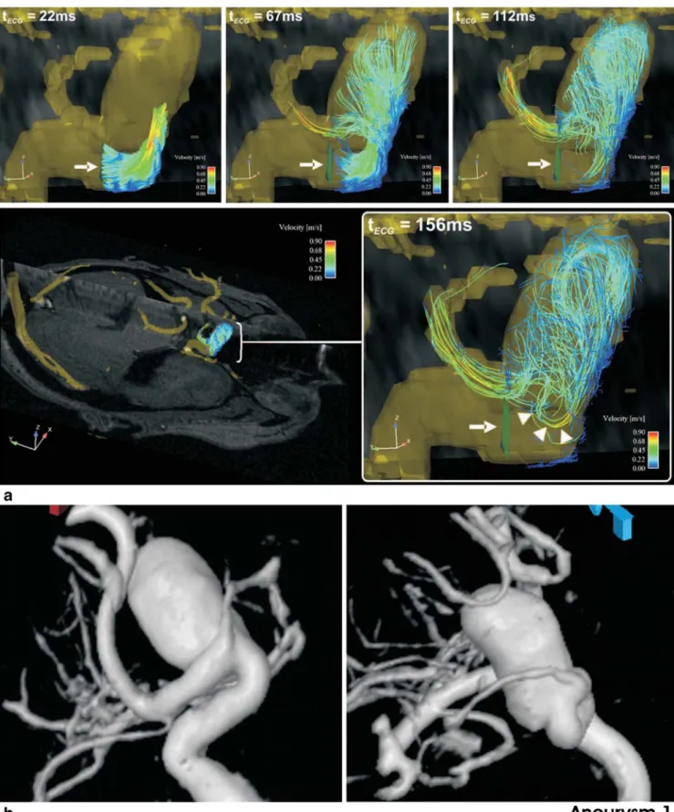
A 54-year-old patient, who presented with symptoms of optic nerve compression, was found to have a large, wide-necked, oval-shaped parophthalmic ICA aneurysm (aneurysm 1, Fig.1). The second patient (age 41 years) had an incidentally diagnosed wide-necked ICA aneurysm located on the medial contour at the proximal knee of the cavernous segment (aneurysm 2). The third patient (age 48 years) was incidentally found to have three aneurysms (Fig.2). Two of these were located at the ICA termination, the larger of which being wide-necked and pointing upward and anteriorly (aneurysm 3). There was a small bleb on its posterior contour. The smaller aneurysm was found to arise from the posterior ICA termination at the origin of the anterior cerebral artery (aneurysm 4). The third aneurysm was located at the middle cerebral artery (MCA) bifurcation
with two M2 branches being incorporated into its neck (aneurysm 5). Thereby, the larger posterior branch followed the angle of the M1 segment.
Flow-sensitized 4-D MR imaging Aneurysmal blood-flow patterns
Vortical blood-flow was the predominant pattern inside all aneurysms. In aneurysm 1, with a high aspect ratio, the inflow stream dispersed into several vortices inside the central and posterior sac (Fig. 1). The configuration, magnitude, and location of these vortices altered consider-ably over one cardiac cycle (Fig.3). Two aneurysms with a low aspect ratio (aneurysms 2 and 4) exhibited singular vortices with spatial and temporal (aneurysm 2, Fig.3), or spatial (aneurysm 4) stability, over one cardiac cycle. In two aneurysms with an intermediate aspect ratio (aneurysms 3 and 5), that were both located at arterial branching sites, only partial spatiotemporal stability of vortical flow over one cardiac cycle was found. The magnitude and orientation of the predominant intraaneurysmal vortex shifted in diastole in both of these aneurysms, either due to smaller low-velocity vortices evolving at the base (aneurysm 3), or due to a second outflow stream into another branch (aneurysm 5). This second outflow stream evolved with delay in the reverse direction to the inflow into a small M2 branch.
In both wide-necked sidewall aneurysms (aneurysms 1 and 2), the blood flow completely entered the aneurysm sac without bypassing flow in the parent arteries. In contrast, flow into aneurysms at branching sites was divided into different streams with variable temporal accentuation, and with part of the flow bypassing the remainder of the aneurysm sac (aneurysms 3–5). For example, the dominant stream was directed into the major M1 branch (aneurysm 3; Fig.2c,d), or into the posterior M2 branch originating from the aneurysm sac (aneurysm 5; Fig.2a,b).
Distinct inflow and outflow zones were distinguishable in all aneurysms except for the smallest (aneurysm 4). Here, only systolic inflow was visible. Between the inflow and outflow zones, predominantly diastolic vortical flow was
observed (Fig. 4; aneurysms 1, 2, 3, and 5), that showed further extension into the downstream artery in aneurysms 2 and 5 (Fig.3).
Blood flow velocity measurements
The results of blood flow velocity measurements in the segmented aneurysms and parent arteries are summarized in Table 2. In all aneurysms, a reduction in intraaneurysmal flow velocity relative to the upstream parent artery was noted. At the aneurysm neck, blood flow velocities were of a similar order to those in the upstream parent artery, except in aneurysm 4. This may have been due to its distant position relative to the major blood flow stream into the M1 segment (Fig.2). In all other aneurysms, a further reduction in blood-flow velocities from the mid level to the dome was observed. This was less pronounced in aneurysm 2, with the lowest aspect ratio.
In the aneurysms at branching sites (aneurysms 3–5), higher velocities were found in streams that followed the angle of the inflow stream into a major branch (Fig.2a, b), relative to other aneurysmal areas or minor branches. For example, the maximum systolic velocity was 26.2 cm/s in the posterior M2 branch vs.16.3 cm/s in the smaller anterior M2 branch (aneurysm 5).
Intraaneurysmal WSS estimations
The results of temporally averaged WSS estimations inside the four medium sized to large aneurysms are summarized in Table3. Due to its small size, WSS was not determined in aneurysm 4.
A high spatial variation of WSS was observed in all aneurysms except aneurysm 2. This wide-necked sidewall aneurysm exhibited uniformly equal or higher WSS relative to the upstream ICA except for a small area on the posterior dome contour. This area corresponded to the wall attach-ment zone of the intraaneurysmal vortex core creating a local minimum of WSS (Fig. 3). In the other three aneurysms, high WSS values, equal to those of the parent arteries, were found in the inflow zone or at the neck Table 1 Angiographic characterization of cerebral aneurysms
Aneurysm Artery Location Dimensions (mm) Aspect ratioa Surface Shape Neck width Depth
1 ICA Parophthalmic (C5) 6.5 14.0 2.2 Smooth Oval
2 ICA Cavernous (C4) 5.7 6.1 1.1 Smooth Round
3 ICA Termination 3.9 6.1 1.6 Lobulated Small bleb
4 ICA Termination 1.5 2.0 1.3 Smooth Oval
5 MCA Bifurcation 3.8 5.5 1.5 Lobulated Oval
a
Fig. 1 Aneurysm 1, a parophthalmic ICA aneurysm. a Time-resolved 3-D particle traces in four consecutive systolic time-frames illustrate the flow dynamics. In all the images, the color coding corresponds to the magnitude of local flow velocity. The emitter plane from which particle traces are released is located in the upstream ICA (white arrows). Note the changing configuration of vortical flow at different time-points over
the cardiac cycle. High-velocity inflow and outflow streams are located in the anterior and posterior aneurysm neck, respectively. Between the inflow and outflow stream, a small vortex evolves at late systole and recirculates into the neck (arrowheads). b 3-D reconstructed DSA images in anterior-posterior and lateral orientations demonstrate the geometry of the aneurysm and the parent ICA
corresponding to high-velocity streams into a major branching artery (aneurysms 1, 3 and 5). In the vicinity of these high WSS zones at the neck, low WSS related to low-velocity vortices was often seen (Fig. 5). In these aneurysms, reduced WSS with high spatial variation was found from the mid level to the dome, e.g. values ranged between 18.9% and 59.7% in aneurysm 1. At the dome, WSS was low, but neither particularly nor uniformly
reduced in relation to the remaining aneurysmal walls, e.g. ranging between 17.9% and 37.3% in aneurysm 3.
Discussion
The in vivo-derived results from flow-sensitized 4-D MR imaging illustrate the complex nature of intraaneurysmal Fig. 2 Aneurysms 3–5, asymptomatic aneurysms. a, c 3-D DSA
images. b, d Time-resolved 3-D particle traces are released from an emitter plane in the distal ICA. The color coding corresponds to the magnitude of local flow velocity. Two aneurysms are located at the ICA termination. The larger, wide-necked aneurysm points upward and anteriorly with a posterior bleb (aneurysm 3; a, b arrowheads). Inside this aneurysm, a horizontal intermediate-velocity vortex is demonstrated (arrowhead in b, d). Highest velocities are observed at the origin of the M1 segment with most streamlines bypassing the aneurysm. Inside the
small posterior ICA termination aneurysm (aneurysm 4; a, c thick arrows), a vertical low-velocity vortex is illustrated (b, d thick arrow). In the wide-necked MCA bifurcation aneurysm (aneurysm 5), two major M2 branches arise from the neck. The majority of streamlines enter the larger, posterior branch (b) that follows the angulation of the inflow stream (a inset arrowheads). Fewer streamlines evolve into the intraaneurysmal vortex (b thin arrow). The remaining streamlines (b) enter the anterior temporal M2 branch in reverse direction to the inflow (a inset)
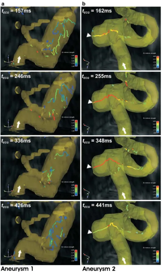
Fig. 3 The distribution of vortical flow in four successive time-frames (systolic to diastolic) is illustrated in the oval-shaped, parophthalmic aneurysm (a aneurysm 1), and in the virtually round-shaped cavernous aneurysm (b aneurysm 2). The core of each vortex is segmented from 3-D flow-velocity fields for all cardiac phases. Vortex core configuration is represented by the colored bars, with the color coding corresponds to the mag-nitude of vorticity, and the di-rection of inflow is indicated (arrows). In aneurysm 1 (a), several vortices of various sizes with temporal changes in mag-nitude, location, and configura-tion are demonstrated. By contrast, in aneurysm 2 (b), a singular high-velocity vortex with a stable configuration and location throughout the cardiac cycle is demonstrated. This vor-tex extends through the aneurysm neck with vortical diastolic outflow into the down-stream ICA. The attachment site of intraaneurysmal vortex core to the posterior dome corre-sponds to a local minimum of WSS (arrowheads)
blood-flow that was recently suggested from in vitro studies with CFD using anatomically“realistic” aneurysm geome-tries [10, 11, 13]. Furthermore, our data suggest that the individual intra-aneurysmal vortical flow pattern and velocity distribution are determined by the aneurysm geometry including the aspect ratio. These preliminary in vivo observations in many aspects accord with the findings of recent in vitro studies using CFD. First, similar to our analysis of a wide-necked parophthalmic ICA aneurysm
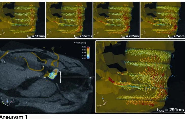
(aneurysm 1), for example, complex structured and tempo-rally unstable vortical flow was observed in a geometrically realistic giant carotid aneurysm model [11]. Second, the geometry of parent/branching arteries, particularly in aneurysms at branching sites, influences the distribution of intraaneurysmal blood flow streams, as well as the magnitude and spatiotemporal evolution of vortical flow. Similarly, Castro et al. observed markedly altered intra-aneurysmal flow patterns with different parent vessel Fig. 4 Time-resolved 2-D vector graphs (five successive systolic to
early diastolic time-frames) illustrate the distribution of flow vectors at the wide neck of the parophthalmic aneurysm (aneurysm 1). The color coding corresponds to the magnitude of local blood flow velocity. The inflow and outflow zones can be differentiated at the anterior and
posterior neck, respectively. The inflow stream is orientated straight upward in systole, and changes to a slightly posterior curved direction in diastole. Low-velocity recirculating flow is seen in the posterior neck. Between inflow and outflow, a small vortical recirculation partly extends from the neck into the ICA lumen
Table 2 Distribution of flow velocities in cerebral aneurysms Aneurysm Flow velocity (cm/s)
Base level Mid sac level Dome level Parent arterya
Maximum systolic Mean Maximum systolic Mean Maximum systolic Mean Maximum systolic Mean
1 50.7 16.3 39.2 13.3 22.7 10.6 49.0 23.3 2 56.5 24.4 46.2 23.7 39.1 22.7 49.2 22.6 3 59.8 26.0 32.1 14.9 29.9 11.7 72.8 35.1 4 23.8 10.3 13.3 6.4 NAb 72.8 35.1 5 47.4 19.6 24.9 12.5 19.7 6.8 41.4 18.9 a
Blood flow velocities in the parent artery were measured upstream of each aneurysm.
b
geometries [10]. Third, a simple geometric classification for cerebral aneurysms (sidewall, sidewall with branching vessel, and endwall) based on flow patterns, and correlated with rupture risk, was suggested in another CFD-based investigation [13]. In accordance with the findings of the latter study, we also observed that the distribution of blood flow velocities was linked to geometric aspects: rather uniformly high velocities were observed in a wide-necked sidewall aneurysm with low aspect ratio, a reduction of velocities towards the dome occurred in all aneurysms with intermediate to high aspect ratios, and low velocities were seen in a small aneurysm with a narrow neck.
Experimental studies have indicated that focal high WSS triggering destructive arterial remodeling is a predisposing factor for cerebral aneurysm formation in healthy arteries [30, 31]. Besides WSS, there are other factors that have been suggested to influence cerebral aneurysm develop-ment and rupture, such as focal structural variations or defects of the arterial wall, or the perianeurysmal environ-ment [32]. However, these factors may be the cause of focal changes in the morphology of the related artery which then can in turn promote local flow disturbances and alterations of WSS. Until recently, many investigators have used geometrically realistic aneurysm models to simulate WSS in vitro with variable results relative to the distribution of WSS [4,9–13,21]. In particular, the role of WSS at the tip or the bleb of an aneurysm is still controversial. One study revealed low WSS inside a tip/bleb [4], whereas others have disclosed high WSS [9,21] with high spatial variation [21] in this area. Our in-vivo-derived results showed a high spatial variation of WSS among different aneurysm geometries reflecting variable flow patterns. In particular, the parent/branching vessel geometry seems to be a predictor of WSS distribution, similar to the results of CFD investigations [10, 11, 13]. We also observed low intraaneurysmal WSS compared to that in the parent arteries, high WSS values adjacent to high-velocity inflow or outflow streams, and variable rather than uniformly low WSS at the dome, except for a sidewall aneurysm with a
low aspect ratio (aneurysm 2). These findings are accor-dance with those of in vitro CFD studies, one of which found a significant and inverse correlation between intra-aneurysmal WSS and aspect ratio [4].
Limitations of the MR technique are as follows. First, the long acquisition time of 25–30 minutes precludes imaging of patients with ruptured aneurysms who are in an unstable neurological condition and require close clinical monitoring. Second, the use of a predefined VENC limits the range of blood flow velocities that can be resolved with PC MR imaging. However, slow vortical blood flow inside a small aneurysm was well resolved at a VENC of 90 cm/s. Third, MR-derived flow data suffer from spatial averaging effects due to voxel size in smaller aneurysms. In addition, temporal averaging of data occurs as the MR acquisition over many heartbeats using ECG gating does not enable flow measurement in real-time but the reconstruction of images representing 16–18 phases of the cardiac cycle. It is well known that these effects may lead to underestimation of flow velocities with 2-D- and 3-D phase-contrast MR imaging by 30–40% in comparison with transcranial Doppler flow measurements [18, 19, 33]. Furthermore, partial volume effects due to the given voxel size may result in an underestimation of the complexity of flow patterns (low-pass filtering). This phenomenon occurs preferentially in smaller aneurysms with only a small number of voxels within the aneurysm lumen. Temporal averaging effects of MR flow data acquisition may also contribute to the masking of beat-to-beat variations or other small dynamic flow features that are too short to be temporally resolved. Fourth, accurate in vivo calculation of WSS with phase-contrast MR remains a challenging task due to the difficulty of precise vascular lumen segmentation, the relative low spatial resolution of acquired MR data (i.e. voxels contain-ing fractions of arterial lumen as well as surroundcontain-ing tissue) and the required smoothing filter. As a consequence, MR-derived estimation of WSS is not possible within a small vascular lumen (<2.5 mm). With larger vascular diameters, it systematically underestimates the actual WSS but Table 3 Distribution of time-averaged relative vectorial WSS in cerebral aneurysms
Aneurysm WSS (%)a
Base level Mid level Dome level
Spatial average Spatial maximum Spatial minimum Spatial average Spatial maximum Spatial minimum Spatial average Spatial maximum Spatial minimum 1 53.0 117.9 20.3 45.3 59.7 18.9 47.0 58.6 36.7 2 99.1 131.1 55.7 118.6 129.6 108.5 92.9 126.9 8.4 3 38.3 81.5 5.3 41.5 53.2 21.2 24.6 37.3 17.9 5 48.3 78.2 14.3 49.1 78.4 23.5 25.8 49.4 10.0
aThe temporally averaged magnitudes of vectorial WSS are presented as percentages of the spatiotemporally averaged vectorial WSS magnitudes
remains correlated with it, and WSS patterns with focal variation or pathological alteration (direction and relative amplitude) can still be detected [14, 34]. Therefore, our approach of normalizing WSS relative to the temporally averaged WSS measured in the parent artery was helpful to focus on focal pathological alterations inside cerebral aneurysms neglecting the global WSS underestimation. Moreover, drawbacks due to resolution and partial volume effects were limited by using an advanced interpolation method based on cubic B-spline. Fifth, observer-related errors which may occur in the segmentation of vessel boundaries can also limit the accuracy of the estimation of WSS. Such segmentations can be difficult to perform with
3-D datasets due to anatomically complex vascular regions, such as curved arteries or aneurysm surfaces, movement of vessel walls, and limited signal-to-noise ratio of the phase contrast data. Therefore, a 2-D approach for interactive segmentation of aneurysm wall segments and estimation of WSS was chosen that facilitated the process of manual segmentation. However, this approach allows complete 3-D coverage of an individual aneurysm using differently angled planes, and calculation of 3-D WSS from phase contrast velocity data.
Technical improvements that focus on the optimization of the trade-off between spatial and temporal resolution, signal-to-noise ratio, and acquisition time, such as parallel Fig. 5 Distribution of WSS is illustrated in the parophthalmic
aneurysm (aneurysm 1). The aneurysmal walls are segmented on interactively placed 2-D planes as indicated by white lines. Gray scaling corresponds to phase contrast magnitude extracted from MR volumes. Temporally averaged relative vectorial WSS (black and white arrowheads) is calculated for 12 clockwise positions on segmented contours (small numbers 1–12). Top row High WSS is seen at the anterior-lateral base adjacent to the inflow stream. Low
WSS is demonstrated at the anterior-medial mid and upper levels, and at the anterior-lateral and posterior-medial neck. Middle row Predom-inantly intermediate to low WSS is observed at the dome and the upper contours of the aneurysmal sac. Bottom row High WSS is seen along the whole circumference of the upstream ICA. Orientations are indicated on the 2-D planes: a anterior, p posterior, m medial, l lateral,t top, b bottom, a-l anterior-medial, p-m posterior-medial
imaging techniques, are required to reduce imaging time and blood flow velocity estimation errors inside small vessels [19]. Another future strategy to optimize accurate vessel lumen segmentation will be a coregistration of phase-contrast MR with high-resolution 3-D angiography data (i.e. 3-D DSA).
In vivo MR imaging has the potential to become a valuable method for intraaneurysmal flow analysis in addition to the numerous in vitro techniques that have been utilized in the past. For example, CFD techniques are limited by simplifying assumptions concerning blood properties (newtonian rheology, incompressibility), bound-ary conditions (idealized pressure/velocities time-courses at inlet and outlet, no-slip on the vessel wall) and concerning vessel properties (rigid wall or simplistic elastic models) [9–11]. Combining in vivo MR imaging and CFD may have the potential to refine CFD models of blood flow. Furthermore, the preliminary in vivo data derived from a small number of different aneurysms can be used for (cross-) validation with CFD methods. Another approach to validation may be invasive in vivo intra-aneurysmal flow measurement with a miniaturized Doppler guidewire that was reported by Benndorf et al. [3]. Besides the potential risk of causing serious neurological complications, such as stroke, this technique can, however, only resolve one-dimensional velocity patterns from many different points using several angles of the probe. Therefore, only deduction of the most likely 3-D flow pattern is possible, as the direction of flow inside the aneurysm cannot be determined a priori [6]. A further benefit of the MR-based 3-D flow analysis is the application advanced postprocessing, such as the vortex core visualization tool. Using this method, the observer’s visual perception and understanding of complex intraaneurysmal vortical flow phenomena was considerably facilitated, thereby enabling direct comparison of vortical low patterns between aneurysms. In particular, the visibility and comprehension of spatiotemporally unstable vortical flow was markedly improved as compared to the applica-tion of 3-D time-resolved particle traces, or 3-D streamline techniques.
In summary, the in vivo assessment of blood flow in cerebral aneurysms using high-resolution flow-sensitized 4-D MR imaging with dedicated 3-D postprocessing, and estimation of WSS derived from 3-D velocity fields was feasible. The technical limitations of MR data acquisition mainly due to spatial and temporal averaging effects can impair the correct determination of flow velocities, flow patterns and WSS estimation, particularly inside smaller aneurysms. However, our preliminary in vivo results in a small number of different aneurysms confirmed those of recent in vitro studies with CFD. Flow patterns, particularly the evolution of vortical flow and the distribution of WSS,
seemed to be dependent on the individual aneurysm and parent/branching artery geometry.
Acknowledgements This work was supported in part by grant number SNF 320000-113492/1 received from the Swiss National Science Foundation (SNF).
Conflict of interest statement We declare that we have no conflict of interest.
References
1. Imbesi SG, Kerber CW (1999) Analysis of slipstream flow in two ruptured intracranial cerebral aneurysms. AJNR Am J Neuroradiol 20:1703–1705
2. Strother CM, Graves VB, Rappe A (1992) Aneurysm hemodynamics: an experimental study. AJNR Am J Neuroradiol 13:1089–1095 3. Benndorf G, Wellnhofer E, Lanksch W, Felix R (1996)
Intra-aneurysmal flow: evaluation with Doppler guidewires. AJNR Am J Neuroradiol 17:1333–1337
4. Shojima M, Oshima M, Takagi K, Torii R, Hayakawa M, Katada K, Morita A, Kirino T (2004) Magnitude and role of wall shear stress on cerebral aneurysm: computational fluid dynamic study of 20 middle cerebral artery aneurysms. Stroke 35:2500–2505
5. Imbesi SG, Kerber CW (2001) Analysis of slipstream flow in a wide-necked basilar artery aneurysm: evaluation of potential treatment regimens. AJNR Am J Neuroradiol 22:721–724 6. Ujiie H, Tachibana H, Hiramatsu O, Hazel AL, Matsumoto T,
Ogasawara Y, Nakajima H, Hori T, Takakura K, Kajiya F (1999) Effects of size and shape (aspect ratio) on the hemodynamics of saccular aneurysms: a possible index for surgical treatment of intracranial aneurysms. Neurosurgery 45:119–129; discussion 129–130
7. Graves VB, Strother CM, Partington CR, Rappe A (1992) Flow dynamics of lateral carotid artery aneurysms and their effects on coils and balloons: an experimental study in dogs. AJNR Am J Neuroradiol 13:189–196
8. Ujiie H, Tamano Y, Sasaki K, Hori T (2001) Is the aspect ratio a reliable index for predicting the rupture of a saccular aneurysm? Neurosurgery 48:495–502; discussion 502–503
9. Tateshima S, Murayama Y, Villablanca JP, Morino T, Nomura K, Tanishita K, Vinuela F (2003) In vitro measurement of fluid-induced wall shear stress in unruptured cerebral aneurysms harboring blebs. Stroke 34:187–192
10. Castro MA, Putman CM, Cebral JR (2006) Computational fluid dynamics modeling of intracranial aneurysms: effects of parent artery segmentation on intra-aneurysmal hemodynamics. AJNR Am J Neuroradiol 27:1703–1709
11. Steinman DA, Milner JS, Norley CJ, Lownie SP, Holdsworth DW (2003) Image-based computational simulation of flow dynamics in a giant intracranial aneurysm. AJNR Am J Neuroradiol 24:559–566 12. Shojima M, Oshima M, Takagi K, Torii R, Nagata K, Shirouzu I, Morita A, Kirino T (2005) Role of the bloodstream impacting force and the local pressure elevation in the rupture of cerebral aneurysms. Stroke 36:1933–1938
13. Hassan T, Timofeev EV, Saito T, Shimizu H, Ezura M, Matsumoto Y, Takayama K, Tominaga T, Takahashi A (2005) A proposed parent vessel geometry-based categorization of saccular intracranial aneurysms: computational flow dynamics analysis of the risk factors for lesion rupture. J Neurosurg 103:662–680
14. Katritsis D, Kaiktsis L, Chaniotis A, Pantos J, Efstathopoulos EP, Marmarelis V (2007) Wall shear stress: theoretical considerations and methods of measurement. Prog Cardiovasc Dis 49:307–329 15. Wigstrom L, Sjoqvist L, Wranne B (1996) Temporally resolved
3D phase-contrast imaging. Magn Reson Med 36:800–803 16. Markl M, Draney MT, Miller DC, Levin JM, Williamson EE,
Pelc NJ, Liang DH, Herfkens RJ (2005) Time-resolved three-dimensional magnetic resonance velocity mapping of aortic flow in healthy volunteers and patients after valve-sparing aortic root replacement. J Thorac Cardiovasc Surg 130:456–463
17. Firmin DN, Gatehouse PD, Konrad JP, Yang GZ, Kilner PJ, Longmore DB (1993) Rapid 7-dimensional imaging of pulsatile flow. Proceedings of the 20th Annual Meeting of Computers in Cardiology, IEEE Computer Society Press, Los Alamitos, pp 353–356 18. Wetzel S, Meckel S, Frydrychowicz A, Bonati L, Radue EW, Scheffler K, Hennig J, Markl M (2007) In vivo assessment and visualization of intracranial arterial hemodynamics with flow-sensitized 4D MR imaging at 3T. AJNR Am J Neuroradiol 28:433–438
19. Bammer R, Hope TA, Aksoy M, Alley MT (2007) Time-resolved 3D quantitative flow MRI of the major intracranial vessels: initial experience and comparative evaluation at 1.5T and 3.0T in combination with parallel imaging. Magn Reson Med 57:127–140 20. Yamashita S, Isoda H, Hirano M, Takeda H, Inagawa S, Takehara Y, Alley MT, Markl M, Pelc NJ, Sakahara H (2007) Visualization of hemodynamics in intracranial arteries using time-resolved three-dimensional phase-contrast MRI. J Magn Reson Imaging 25:473– 478
21. Ahn S, Shin D, Tateshima S, Tanishita K, Vinuela F, Sinha S (2007) Fluid-induced wall shear stress in anthropomorphic brain aneurysm models: MR phase-contrast study at 3 T. J Magn Reson Imaging 25:1120–1130
22. Tateshima S, Grinstead J, Sinha S, Nien YL, Murayama Y, Villablanca JP, Tanishita K, Vinuela F (2004) Intraaneurysmal flow visualization by using phase-contrast magnetic resonance imaging: feasibility study based on a geometrically realistic in vitro aneurysm model. J Neurosurg 100:1041–1048
23. Isoda H, Hirano M, Takeda H, Kosugi T, Alley MT, Markl M, Pelc NJ, Sakahara H (2006) Visualization of hemodynamics in a silicon aneurysm model using time-resolved, 3D, phase-contrast MRI. AJNR Am J Neuroradiol 27:1119–1122
24. Walker PG, Cranney GB, Scheidegger MB, Waseleski G, Pohost GM, Yoganathan AP (1993) Semiautomated method for noise reduction and background phase error correction in MR phase velocity data. J Magn Reson Imaging 3:521–530
25. Buonocore MH (1998) Visualizing blood flow patterns using streamlines, arrows, and particle paths. Magn Reson Med 40:210–226 26. Sujudi D, Haimes R (1995) Identification of swirling flow in 3-D vector fields. Proceedings of the 12th AIAA Computational Fluid Dynamics Conference, San Diego, paper 95-1715
27. Stalder AF, Frydrychowicz A, Russe MF, Bock J, Hennig J, Markl M (2007) Methodology for optimal quantitative flow analysis by planar analysis of CINE phase contrast 2D or 3D MR data. Proceedings of the 15th Scientific Meeting of the International Society for Magnetic Resonance in Medicine, Berlin, e-poster no. 3139
28. Unser M (1999) Splines – a perfect fit for signal and image processing. IEEE Signal Processing Magazine 16:22–38 29. Papathanasopoulou P, Zhao S, Kohler U, Robertson MB, Long Q,
Hoskins P, Xu XY, Marshall I (2003) MRI measurement of time-resolved wall shear stress vectors in a carotid bifurcation model, and comparison with CFD predictions. J Magn Reson Imaging 17:153–162
30. Sadamasa N, Nozaki K, Hashimoto N (2003) Disruption of gene for inducible nitric oxide synthase reduces progression of cerebral aneurysms. Stroke 34:2980–2984
31. Fukuda S, Hashimoto N, Naritomi H, Nagata I, Nozaki K, Kondo S, Kurino M, Kikuchi H (2000) Prevention of rat cerebral aneurysm formation by inhibition of nitric oxide synthase. Circulation 101:2532–2538
32. San Millan Ruiz D, Yilmaz H, Dehdashti AR, Alimenti A, de Tribolet N, Rufenacht DA (2006) The perianeurysmal environment: influence on saccular aneurysm shape and rupture. AJNR Am J Neuroradiol 27:504–512
33. Oktar SO, Yucel C, Karaosmanoglu D, Akkan K, Ozdemir H, Tokgoz N, Tali T (2006) Blood-flow volume quantification in internal carotid and vertebral arteries: comparison of 3 different ultrasound techniques with phase-contrast MR imaging. AJNR Am J Neuroradiol 27:363–369
34. Frydrychowicz A, Markl M, Harloff A, Stalder AF, Bock J, Bley TA, Berger A, Russe MF, Schlensak C, Hennig J, Langer M (2007) Flow-sensitive in-vivo 4D MR imaging at 3T for the analysis of aortic hemodynamics and derived vessel wall parameters. Rofo 179:463–472