Design and Optimization of Micro Aerial Vehicles
by
Sarah N. Saleh
Submitted to the Department of Aeronautics and Astronautics
in partial fulfillment of the requirements for the degree of
Master of Science in Aeronautics and Astronautics
at the
MASSACHUSETTS INSTITUTE OF TECHNOLOGY
May 2003
@
Massachusetts Institute of Technology 2003. All rights re
ifapST
OF TECHNOLOGY
SEP
1 0 2003
Author ...
...
LIBRARIES
Department of Aeronautics and Astronautics
May 9, 2003
Certified by...
i
bJohn
J. Deyst
Professor of Aeronautics and Astronautics
Thesis Supervisor
Certified by...
...
Sean George
Draper Laboratories
I'LThesis
/
Supervisor
Certified by...
...
...
Bernard F. Mettler
Laboratory for Information and Decision Systems
A
Thesis Supervisor
Accepted by...
..
Edward M. Greitzer
H.N. Slater Professor of Aeronautics and Astronautics
Chairman, Committee on Graduate Students
Design and Optimization of Micro Aerial Vehicles
by
Sarah N. Saleh
Submitted to the Department of Aeronautics and Astronautics on May 9, 2003, in partial fulfillment of the
requirements for the degree of
Master of Science in Aeronautics and Astronautics
Abstract
This thesis details the optimization and development of two Micro Aerial Vehicles (MAVs), namely a fixed wing vehicle and a quadrotor vehicle, within the Parent Child Unmanned Air Vehicle (PCUAV) system developed at MIT and the Draper Laboratory. The PCUAV system allows up close surveillance using a three-tiered system, of which the MAVs comprise the lowest altitude tier to the ground. MAVs are defined by the Department of Defense as having a span of 6 inches, and can be used to increase situational awareness by obtaining damage assessment and surveillance information. In addition to these military uses the MAVs can be used for applications such as search and rescue, air sampling and urban surveillance. A Multidisciplinary System Design Optimization (MSDO) method was used to optimize each of the vehicle configurations for a particular mission.
Thesis Supervisor: John J. Deyst
Title: Professor of Aeronautics and Astronautics
Thesis Supervisor: Sean George Title: Draper Laboratories
Thesis Supervisor: Bernard F. Mettler
Acknowledgments
In the Name of God the Most Gracious, the Most Merciful
To only thank a limited number of advisors, friends and family in this section is hard, since there are many people that have affected me in many ways. So to all my friends that I have not mentioned below, thank you all for helping me grow and develop academically, spiritually and socially.
I would like to thank Professor Deyst, for giving me the opportunity of a life time to study the field of my dreams. For being an advisor not just in my area of study but in life. Thanks for being such a wonderful role model. My thanks also to Mrs. Deyst who throughout my studies here has encouraged my growth in many aspects.
Sean- thank you for your all your help, and the countless hours that you spent with me working on "my models" and the many 2 hour meetings that we would have early on Wednesday mornings. I appreciate your enthusiasm for my work and your constant good humor and encouragement.
Professor Mettler- Thank you for the many hours that you put into this work, and a wonderful helicopter course that provided me with the background to complete this work.
I would like to thank Brent Appleby and Chris Andersen at Draper Labs for their direction and guidance throughout the project.
To Don, Dick, Carol, Doris and Phyllis, for all your support and in making my time at MIT easy and stress free.
To my friends in Calgary who encouraged me to pursue my dreams, especially Dr. Jason Mukherjee and Dr. Kentfield, who without their advice and efforts I would not
be here doing what I love.
Thanks also to the team -who treated me like their little sister! Francois and Thomas-thank you both for your leadership and dedication to the team, Sanghuk- Thomas-thanks for many precious AVL moments, and the help that you have given to me since I joined the team, Damien- thanks for your sincerity and care, Anand- thanks for teaching me the joys and effects of coffee at "Starbooks", Jason- thanks for all your aero stories and Alex- thanks for teaching me about Russia and Hockey!
To my friends in the Muslim Students' Association and at the Islamic Society of Boston, JazakumAllah Khairan, for making these few years the best in my life, I will remember each and everyone of you for everything that you have taught me.
And finally to my family who throughout my life, have encouraged me to follow my dreams and have nurtured me. To my sisters Mona and Susan- who have been with me since day one...thanks for making me who I am, and for constantly putting me above yourselves. To Mummy and Daddy, I couldn't wish for greater parents. Thanks for giving me the opportunities to grow. Thanks for always being there for me, picking me up when I have been down and sacrificing your needs for mine. I hope that one day, I will be able to give to you what you have given to me. May Allah (SWT) give you the best in this life and the next.
Contents
1 Introduction & Overview
1.1 Background & Motivations . . . . 1.2 Thesis Contributions . . . . 1.3 Organization of Thesis . . . . 1.4 Intended Audience . . . . 2 PCUAV System 2.1 Chapter Overview . . . . 2.2 Concept Elaboration . . . . 2.2.1 PCUAV Mission Scenario . . . . 2.2.2 Key Enablers . . . . 2.3 Reintegration . . . . 2.4 PCUAV Vehicles and Components . . . . 2.4.1 Parent Vehicle . . . . 2.4.2 M ini Vehicle . . . . 2.4.3 Micro Aerial Vehicles (MAVs) . . . . 2.4.4 Clandestine Mid Air Retrieval System (CMARS) 2.4.5 Communications & Surveillance . . . .
3 MAV Selection
3.1 Chapter Overview . . . . 3.2 Importance of Micro Aerial Vehicles . . . . 3.3 Requirements & Mission Definition . . . .
23 . 23 . 24 . 24 . 25 27 . . . . 27 . . . . 27 . . . . 28 . . . . 29 . . . . 30 . . . . 31 . . . . 32 . . . . 33 . . . . 34 . . . . 35 . . . . 36 37 37 37 38
3.3.1 MAV Requirements ...
3.3.2 Mission Definition . . . . 3.3.3 Physical MAV Requirements . . 3.3.4 MAV Performance Requirements 3.4 Current MAVs & QFD Analysis . . . . 3.4.1 Current MAVs . . . . 3.4.2 QFD Analysis . . . .
3.4.3 QFD Results . . . . 4 Optimization Model Design
4.1 Chapter Overview . . . . 4.2 Problem Definition & Objectives 4.3 Mission Definitions . . . .
4.3.1 Fixed Wing Mission . . . 4.3.2 Quadrotor Mission . . . . 4.4 Module Definition . . . . 4.4.1 Aerodynamics . . . . 4.4.2 Weight . . . . 4.4.3 Propulsion . . . . 4.4.4 M otor . . . . 4.4.5 Battery . . . . 4.4.6 System Structure . . . . . 4.5 Model Commonality . . . . 4.5.1 Design Variables . . . . . 4.5.2 Design Constants . . . . . 4.5.3 4.5.4
Mission Parameters and Nominal Mission. Model Analysis Approach . . . .
5 Fixed Wing 5.1 Chapter Overview . . . . 5.2 Mission Definition . . . . 8 39 39 40 41 42 42 42 46 51 51 51 52 52 53 54 55 55 56 56 56 58 60 61 61 61 62 65 65 65 . . . . . . . . . . . . . . . . . . . . . . . . . . . . . . . .
5.3 Design & Numerical Implementation . . . . 5.3.1 Geometry Calculations . . . . 5.3.2 Weight Calculations . . . . 5.3.3 Aerodynamic Calculations . . . . 5.3.4 Force Calculations . . . . 5.3.5 Propulsion Calculations . . . . 5.3.6 Motor Calculations . . . . 5.3.7 Energy Calculations . . . . 5.3.8 Overall Model Summary . . . . 5.4 Optimization Study-Results & Analysis . . 5.4.1 Nominal Vehicle Designs . . . . 5.4.2 Weight Trends for Nominal Missions 5.4.3 Secondary Parameters . . . .
6 Quadrotor
6.1 Chapter Overview. . . . . 6.2 Mission Definition. . . . . 6.3 Design & Numerical Implementation . . . . 6.3.1 Quadrotor Theory . . . . 6.3.2 Definitions . . . . 6.3.3 Weight Calculations . . . . 6.3.4 Aerodynamic Calculations . . . . 6.3.5 Force Calculations . . . . 6.3.6 Propeller Power Calculations . . . . . 6.3.7 Motor Power Calculations . . . . 6.3.8 Overall Model Summary . . . . 6.4 Optimization Study-Results and Analysis
6.4.1 Nominal Vehicle Designs . . . . 6.4.2 Weight Trends for Nominal Mission . 6.4.3 Secondary Parameters . . . . . . . . 6 6 . . . . 6 7 . . . . 7 5 . . . . 7 6 . . . . 7 9 . . . . 8 0 . . . . 8 1 . . . . 8 2 . . . . 8 3 . . . . 8 4 . . . . 8 4 . . . . 8 5 . . . . 9 3 97 . . . . 9 7 . . . . 9 7 . . . . 9 8 . . . . 9 8 . . . . 9 9 . . . . 10 0 . . . . 10 3 . . . . 10 8 . . . . 10 9 . . . . 1 10 . . . .111 . . . .111 . . . . 1 12 . . . . 1 13 . . . . 1 19
7 Conclusion
7.1 Chapter Overview. . . . . 7.2 Comparative Results . . . . 7.2.1 Loiter Radius/Hover Comparison 7.2.2 Loiter Velocity . . . . 7.2.3 Weight Comparison . . . . 7.2.4 Effect of Parameters . . . . 7.2.5 Qualitative Study . . . . 7.3 Conclusions . . . . 7.4 Future Work . . . . A Battery Macros
B Fixed Wing Model C Spar Sizing D Quadrotor Model 10 123 123 123 123 124 125 126 127 129 130 133 135 139 141 . . . . . . . .
List of Figures
2-1 Multi-tiered System Concept . . . . 2-2 Communications Hierarchy for PCUAV [13] . . . .
Phase One of Reintegration . . . . . Phase 2, Optical System . . . . Outboard Horizontal Stabilizer Parent bled for Transportation in a Van . . . New Generation Mini (NGM) II . . . CMARS Directional Finder . . . . . Rover with Surveillance Equipment .
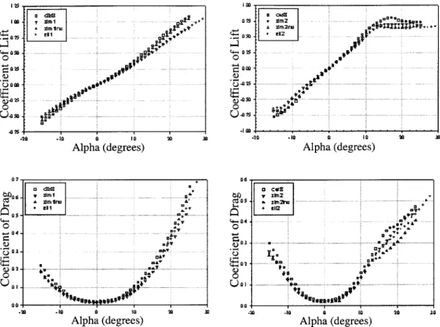
Mission Overview . . . . QFD Diagram [4] . . . . Initial QFD Definition . . . . Ragone Plot . . . . N2 Diagram . . . . System Simulation . . Mission Overview . . . Wing Shapes [16] . . . Lift and Drag Coefficien Wings [16] . . . . 2-3 2-4 2-5 2-6 2-7 2-8 3-1 3-2 3-3 4-1 4-2 4-3 5-1 5-2 5-3 28 29 30 31 Vehicle in Flight and
Disassem-. Disassem-. Disassem-. Disassem-. Disassem-. Disassem-. Disassem-. Disassem-. Disassem-. Disassem-. Disassem-. Disassem-. Disassem-. 3 3 . . . . 3 4 . . . . 3 5 . . . . 3 6 . . . . 4 0 . . . . 4 3 . . . . 4 6 . . . . 5 7 . . . . 5 9 . . . . 6 0 . . . . 6 6 . . . . 6 7
Angle of Attack for Low Aspect Ratio
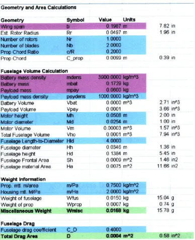
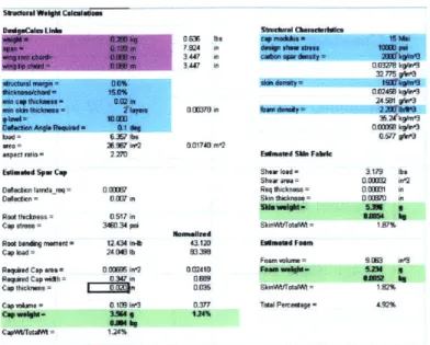
5-4 Geometry and Area Calculations for the Fixed Wing MAV . . . . 5-5 Structural Calculations for the Fixed Wing MAV . . . .
68 69 71 Lts Vs.
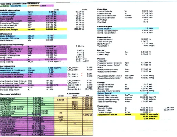
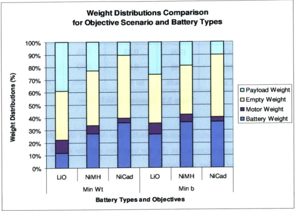
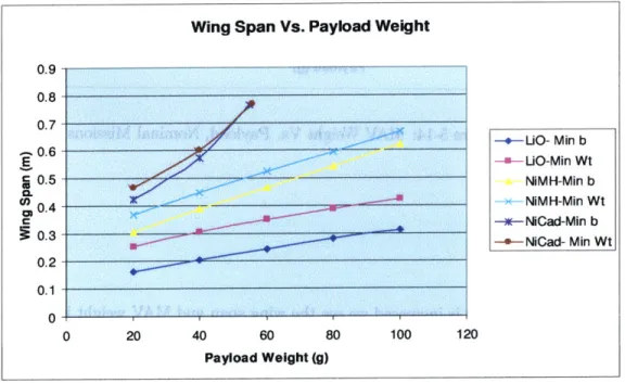
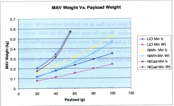
5-6 5-7 5-8 5-9 5-10 5-11 5-12 5-13 5-14 5-15 5-16 5-17 5-18 5-19 5-20 5-21 5-22 6-1 6-2 6-3 6-4 6-5 6-6 6-7 6-8 6-9 6-10 6-11 6-12 D eflections . . . . Fixed Wing MAV- Wing Structure [2] . . . . Reynolds Numbers for a Range of Vehicle Sizes [20] . . . . . Free Body Diagram -Loiter Radius . . . . Fixed Wing MAV (Main Worksheet) . . . . Fixed Wing Model Block Diagram . . . . Normalized Weight Distribution Comparison for the Nomina Wing Span Vs. Payload Weight, Nominal Mission . . . . MAV Weight Vs. Payload, Nominal Missions . . . . Wing Span Vs. Loiter Time, Nominal Mission . . . . MAV Weight Vs. Loiter Time, Nominal Missions . . . . Wing Span Vs. Loiter Radius, Nominal Mission . . . . MAV Weight Vs. Loiter Radius, Nominal Missions . . . . . Wing Span Vs. Cruise Distance, Nominal Mission . . . . MAV Weight Vs. Cruise Distance, Nominal Missions . . . . Secondary Effects on AR and Mission Energy whilst varying Loiter Radius Effects on AR and Mission Energy . . . .
Quad-rotor Mission Definition . . . . Quadrotor Model (Geometry and Area Calculations) . . . . Quadrotor Assembly . . . . Simplified Quadrotor (Cross Section) for Drag Calculations . Quadrotor Model (Figure of Merit Calculations) . . . . Quadrotor Maneuvering Forces . . . . Quadrotor Model (Main Worksheet) . . . . Quadrotor Model Block Diagram . . . . Weight Distribution Comparison for Nominal Missions . . . MAV Weight Vs. Cruise Distance, Nominal Mission . . . . . Rotor Diameter Vs. Cruise Diameter, Nominal Mission . . . Weight Distribution Comparison- Cruise Distance . . . .
payl 12 lMis . . . 73 . . . 73 . . . 77 . . . 79 . . . 83 . . . 84 sion 86 . . . 87 . . . 88 . . . 89 . . . 89 . . . 90 . . . 91 . . . 92 . . . 92 oad 95 . . . 96 98 101 102 104 106 109 112 113 114 115 116 117
6-13 6-14 6-15 6-16 6-17 6-18
MAV Weight Vs. Payload Weight, Nominal Mission . . Rotor Diameter Vs. Payload Weight, Nominal Mission Weight Distribution Comparison- Payload . . . . MAV Weight Vs. Hover time, Nominal Mission . . . . Rotor Diameter Vs. Hover time, Nominal Mission . . . Weight Distribution Comparison- Hover Time . . . . .
7-1 Vehicle Separated Weight Comparison . . . . 7-2 Vehicle Weight Comparison . . . .
A-1 Battery Macro . . . .
118 118 119 120 121 121 125 126 . . . . 134
Geometry and Area Calculations for the Fixed Wing MAV Structural Calculations for the Fixed Wing MAV . . . . . Fixed Wing MAV (Main Worksheet) . . . . 136 137 138 140 C-1 Spar Sizing Text Example [6] . . . . Quadrotor Model (Main Worksheet) . . . . Quadrotor Model (Geometry and Area Calculations) . . . Quadrotor Model (Figure of Merit Calculations) . . . . Quadrotor Model (Velocity Macro) . . . . . . . . 141 . . . . 142 . . . . 143 . . . . 144 B-i B-2 B-3 D-1 D-2 D-3 D-4
List of Tables
3.1 Hierarchy of Requirements Affecting MAV Choice . . . . 47
3.2 Factors Affecting MAVs . . . . 49
4.1 Battery Energy Densities . . . . 58
4.2 Design Variables Common to both MAV Optimizations . . . . 61
4.3 Design Constants Common to both MAV Optimizations . . . . 62
4.4 Parametric Mission Value Samples . . . . 62
5.1 Fixed Wing Geometry Related Constants . . . . 70
5.2 Fixed Wing Structural Weight Constants . . . . 72
5.3 Nominal Vehicle Sizes . . . . 85
5.4 Secondary Variable Trends, Objective: Minimizing Wing Span . . . . 93
5.5 Secondary Variable Trends, Objective: Minimizing Weight . . . . 94
6.1 Material Properties and Constants for Weight and Geometric Calcula-tions . . . . 103
6.2 Constants for Figure of Merit Calculations . . . . 106
6.3 Nominal Vehicle Sizes . . . . 113
6.4 Variable Trends, Objective: Minimizing Rotor Diameter . . . . 122
6.5 Variable Trends, Objective: Minimizing Weight . . . . 122
7.1 Loiter Radius Comparison . . . . 124
7.2 Minimum Loiter Velocities . . . . 124
Nomenclature
a Vehicle Angle
rn Efficiency/Figure of Merit
rK Induced Power Factor
Adef Required Angular Deflection
Q Rotor Tip Speed
<$ Bank Angle
p Density
0- Rotor Solidity
-cap Cap Stress
Tskin Required Skin Thickness
Subscripts
a Material area
bat Battery
Cp Cruise Power
cap Cap
c Cruise dc Cruise Drag dens Density d Diameter foam Foam foil Airfoil fuse Fuselage f Flight ho Housing h Height h Hover if Flight Induced ih Hover Induced Loiter mc Motor Cruise mh Motor Hover misc Miscellaneous ml Motor Loiter m Maneuvering pay Payload PC Propeller Cruise 18
pf Propeller Flight ph Propeller hover ,1 Propeller Loiter prop Propeller r Root skin Skin struct Structure A Area
ADj Component Drag Area
BL Blade Loading
BW Battery Weight
c Propeller Chord
c/R Propeller Chord Ratio
CD Fixed Wing Fuselage Drag Coefficient
Cd Drag Coefficient
CT Coefficient of Thrust
Cd Profile Drag Coefficient
Cduse Fuselage Drag Coefficient
C _Lax Maximum Coefficient of Lift
CL Coefficient of Lift
Di Component Drag
DL Disk Loading
E Energy
e Oswald Efficiency
H Fuselage/Housing
Hid Fixed Wing Fuselage Length:Diameter ratio
k Induced Drag Factor
M Motor
m Mass
Mb Root bending moment
N Number
n Load Factor
P Power
R Radius
Re Reynolds Number
Re, Rotor Reynolds Number
S Area T Thrust t Time V Velocity V Volume 20
W Weight
w Width
AR Aspect Ratio
ATA Avionics Testbed Aircraft
BEMT Blade Element Momentum Theory
CCR Cruise Climb Rate
CMARS Clandestine Mid Air Retrieval Systems
GPS Global Positioning Systems
L Load
LCR Loiter Climb Rate
LED Light Emitting Diode
MAV Micro Aerial Vehicle
MDPP MIT Draper Partnership Project
MPIM Mini-Parent Integration Mechanism
MSDO Multidisciplinary system design optimization
NGM New Generation Mini
OHS Outboard Horizontal Stabiliser
PCUAV Parent Child Unmanned Aerial Vehicle
PDV Payload Delivery Vehicle
UAV Unmanned Aerial Vehicle
WLAN Wireless Local Area Network
y Deflection
Chapter 1
Introduction & Overview
1.1
Background & Motivations
In the last seven years, as military needs grow, the requirement to obtain up close/fine scale reconnaissance information from a distance has become increasingly evident. The Massachusetts Institute of Technology (MIT) and The Charles Stark Draper Laboratory (Draper) responded to this need by forming a technology development partnership in 1996.
The partnership was formed not only to address the need for up-close surveillance and designing leading edge innovative systems, but also to allow for graduate students studying at MIT to be exposed to project engineering and a life cycle of a critical academic and industrial problem.
The partnership began with the Wide Area Surveillance Projectile Project (WASP), where students designed a canon-launched folding-wing projectile, which was later marketed by Draper.
After the WASP project came the Parent Child Unmanned Aerial Vehicle Project, PCUAV, which still focused on the main objective of the WASP project by providing close-up surveillance from a distance.
a hierarchy of unmanned vehicles to work together to obtain information otherwise not obtainable by just one of the individual vehicles. These vehicles range from a large parent vehicle, with a tail span of approximately 21ft, to small micro aerial vehicles, MAVs, whose lengths can be as small as 6 inches.
In 2002 the PCUAV project came to a successful end, and was followed by the MIT Draper Partnership Project (MDPP). The purpose of this new project is to con-tinue work in the area of up-close surveillance by looking at areas such as unmanned precision delivery, coordinated operation of sensor networks and probing ground and aerial vehicles, areas of research that will allow the set-up of an entire communications network in hostile environments.
1.2
Thesis Contributions
The work completed for this thesis provides:
" An analysis of current MAV designs on the market
" A software environment for use in the initial design of both a fixed wing MAV and a quadrotor MAV.
" A multidisciplinary system design optimization of two MAVs
1.3
Organization of Thesis
In chapter 1, we discuss the history of the MDPP and the needs for up-close surveil-lance.
Chapter 2 outlines the PCUAV system and delves into the vehicles of PCUAV, navi-gation techniques, and communications and surveillance systems. In this chapter we also introduce one of the key capabilities of PCUAV: reintegration of two UAVs.
Chapter 3 on, focuses on MAVs, specifically with the PCUAV project in mind. Cur-rently available off-the-shelf MAVs and potential mission scenarios, that will enhance the capabilities of the PCUAV system are examined.
Chapter 4 delves into the design challenges and requirements to set up an Excel opti-mization of both fixed wing and quadrotor MAVs. We study further the parameters that constrain the multidisciplinary system design, the design variables, and how to build optimization models for both MAVs.
Chapters 5 and 6 discuss in more detail the design challenges and theory involved in building a fixed wing and quadrotor optimization model. We analyze the aerodynamic theory and design of both the fixed wing and quadrotor MAVs, and set up the Excel Optimization model. Finally we analyze the results of the optimization for both vehicles.
In chapter 7, we compare the results from chapters 5 and 6 and quantitatively look at the factors that would determine the number and type of MAVs needed for a specific surveillance mission. Finally we conclude our work and discuss potential future work in this area.
1.4
Intended Audience
This thesis is intended to be read by individuals interested in:
" Multidisciplinary system design optimization (MSDO)
" Flight vehicle design of MAVs
Chapter 2
PCUAV System
2.1
Chapter Overview
This chapter presents an overview of the PCUAV project and describes the system's concepts, requirements, and missions.
2.2
Concept Elaboration
The original motivation for the PCUAV project was to allow someone sitting at their desk in Boston to take a "virtual walk" through Central Park in New York City (over two hundred miles away); by using information being relayed back through a fleet of unmanned aerial vehicles (UAVs). Through this basic idea the PCUAV mission became to:
"Perform real-time and continuous up-close surveillance of a low altitude cluttered environment using low-cost assets, from a distance."
The overall architecture of the PCUAV project consists of a fleet of UAVs organized in a three-tiered system (Figure 2-1). The system is designed so that each vehicle can be used at different desired altitudes, relaying important information from each tier and providing the necessary energy for the smaller lower-energy vehicles to be transported to the area of interest.
Tier 1: Parent Vehicle (20 000 ft)
Tier 2: Mni Vehicles
(10 000 ft)
Tier 3: MLAVs
(200ft)
Figure 2-1: Multi-tiered System Concept
This setup is useful for a number of different missions in which it is hazardous to dis-patch humans. These missions include, collecting soil or water samples from nuclear waste sites, obtaining battle-zone damage assessment information, and for search and rescue scenarios.
The advantages of using such a system over currently available reconnaissance systems like the Predator, are as follows:
" The flexibility and modularity of each vehicle on its own allows for reconfigura-tion of the vehicles for a broad range of missions and deployment platforms.
" Smaller vehicles (micros) can operate for hazardous, up-close surveillance and are low-cost expendable vehicles.
* Obtain the same high value, long range as the Predator, using the Parent.
2.2.1
PCUAV Mission Scenario
In a typical mission, a parent vehicle would be loaded with two mini vehicles, a number of payload delivery vehicles (PDVs) and micro aerial vehicles (MAVs), and enough fuel to last for a trip of up to 350km, with a surveillance/loitering time of approximately 5 hours over the target. The parent would take off from an airport or
an unapproved landing strip, and fly to the area of interest autonomously or remotely. A communications link is established and maintained with a ground operator from the time of departure until the time of return. At the site of interest the parent would deploy the mini vehicles that descend to lower altitudes for surveillance, until running low on fuel, where the minis would then rendezvous with the parent, and either redock or refuel.
While the minis gather information, the PDVs and MAVs are deployed to collect finer reconnaissance information (for example, under-the-tree-canopy surveillance or obtaining soil samples). These samples are then retrieved by a balloon rendezvous system with the mini vehicles and brought back to the parent (and later the base station) using clandestine mid air retrieval systems (CMARS). During the entire mission a communications system maintains real-time communication between all the vehicles and the ground station, allowing for redefinition of the mission, if necessary
(Figure 2-2). PAREP47 *i P TO IVU MLLEZ -30u FLc~r INI -~~~ "' 30 FEET UPj~ERAT'MR/
Figure 2-2: Communications Hierarchy for PCUAV [13]
2.2.2
Key Enablers
To be able to perform the mission, we need a number of key enablers:
" A parent vehicle that is capable of long distance flight and carrying payloads that may have an effect on the overall stability of the vehicle.
9 A robust and dynamic communications network between all vehicles.
We will look at these key enablers in more detail in later sections.
2.3
Reintegration
601 401 4 201 800 600 40( 2( y axis -200 0 200 400 x axisFigure 2-3: Phase One of Reintegration
Since both vehicles are unmanned and autonomous, the concept of joining two ve-hicles in the air, although not new, presents many control and design challenges. Establishing a routine for both the mini and the parent to follow, for rendezvous, is critical to the success of the mission, so that the chances of a "mission abort" are minimized. To overcome this, reintegration is comprised of three phases:
1. Phase 1: Brings both aircraft, the parent and the mini, from arbitrary positions
and velocities in the sky to a point where the parent and mini have a relative position of 10m.
2. Phase 2: Brings the mini into contact with the parent.
3. Phase 3: Locks the parent and the mini in place.
Phase 1 has been demonstrated by PCUAV and we are currently awaiting testing of Phase 2. The details of Phase 1 can be seen in Figure 2-3 and involve the mini performing a trajectory that intercepts the parent's position.
Phase 1 is performed using GPS and proportional navigation. Phase 2 begins once the mini is in the proper position behind the parent. In this phase an optically-based system is used to bring the mini vehicle from 10m behind the parent to physical contact with the parent. We use a video camera mounted on the mini vehicle to track signals from infrared LEDs on the parent vehicle (Figure 2-4) to guide the mini to the parent vehicle. This system is able to compute the relative position of the aircraft to an accuracy of a few of millimeters.
Mini
OHS Sm
optical sensor
measures angles to the target 4kHz Pulse
Diode Array
Figure 2-4: Phase 2, Optical System
2.4
PCUAV Vehicles and Components
This section gives a brief description of the vehicles and the components that make up the three tiers of PCUAV. These include the parent, the mini, the avionics testbed aircraft (ATA) and the payload delivery vehicles (PDV), along with the mini-parent integration mechanism (MPIM), communications and surveillance and avionics.
2.4.1
Parent Vehicle
In order to demonstrate the system concepts of PCUAV, the parent vehicle needed to be able to:
* Navigate autonomously.
" Loiter for 30-60 minutes.
" Maintain speeds suitable for reintegration and provide a stable target for the mini to dock with.
" Continue flying after docking with one mini.
* Operate from unapproved runways and fields
" Be transportable in a convenient package.
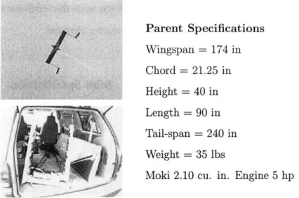
After having studied a number of different vehicle designs, we decided to use the outboard horizontal stabiliser (OHS) design for ease of reintegration [11] [10] [12]. This design (Figure 2-5) has a number of advantages over a conventional design, since:
1. It has a unobstructed space behind the parent, as the tails are well outboard of the main wing, reducing interference of the parent and the mini, and allowing a large area for the docking of the mini with the parent.
2. More lift is possible with the same size wing as a conventional aircraft, since the tails are positioned in the wing tip vortices, allowing the tail to lift.
3. The aircraft is still controllable if one of the tails is lost.
4. The OHS can be built in a modular fashion, allowing for easy transportation (Figure 2-5).
Parent Specifications Wingspan = 174 in Chord = 21.25 in Height = 40 in Length = 90 in Tail-span = 240 in Weight = 35 lbs
Moki 2.10 cu. in. Engine 5 hp
Figure 2-5: Outboard Horizontal Stabilizer Parent Vehicle in Flight and Disassembled for Transportation in a Van
2.4.2
Mini Vehicle
The requirements for the mini vehicle were as follows:
" Fly and navigate autonomously.
" Maintain a speed appropriate for reintegration.
" Maneuver to be able to "hit" a target on the parent for reintegration.
" Minimize detrimental effects on the flight of the parent.
In order to satisfy the requirements, the mini vehicle was designed to feature a pusher propeller, a vertical direct force fin, and flaperons that can produce both rolling moments and direct lift forces. The pusher configuration decreases the likelihood of propeller strike when the mini approaches the parent from behind, and also clears an area for a probe to protrude from the nose of the mini for reintegration. The vertical fin with its associated control surface, over the center of gravity of the aircraft, creates the possibility of moving side to side without yawing or banking, when the fin surface deflection is combined with both aileron and rudder deflections. Similarly, it
is possible to make the plane move up and down with the combination of flaperons, elevator and throttle; without pitching or changing airspeed.
Mini Specifications Wingspan = 100 in Chord = 11 in Height = 25 in Length = 65 in Weight = 15 lbs 0.91 cu. in OS Engine
Figure 2-6: New Generation Mini (NGM) II
2.4.3
Micro Aerial Vehicles (MAVs)
Two types of MAVs were examined to provide even closer surveillance information. These vehicles could be used to drop off sensors; however, their primary use is surveil-lance and to act as accurately-placed communications nodes. A fixed wing vehicle and a rotating hovering vehicle (quadrotor) were designed and optimized, and will be addressed in following chapters in greater detail.
To carry out their mission it is necessary for both vehicles to meet the following requirements:
" Be capable of image detection (surveillance).
" Have sufficient obstacle avoidance for operation in cluttered environments.
" Be deployed from the parent or mini vehicles.
2.4.4
Clandestine Mid Air Retrieval System (CMARS)
During the course of a typical mission it is desirable to be able to recover sensors or soil samples from the ground. A clandestine mid air retrieval system (CMARS) was developed by PCUAV to provide a cost-effective solution to recovering elements from the ground. The system consists of a balloon to carry the desired package, an RF transmitter attached to the balloon, and a directional receiver onboard the rendezvousing aircraft.
To collect a soil sample, for example, first a mini or MAV would deliver a collector from the parent to the site of interest. A sample would be gathered by the collector, the balloon would inflate bringing the collector to the altitude of the mini, where an RF transmitter would send an omnidirectional signal. The receiver on the mini would find the bearing toward the transmitter and steer the mini towards it. Finally the mini would then fly through a cable that connects the sample to the balloon, and retrieve the sample at the wing-tip while cutting away the balloon.
We designed, constructed and tested a transmitter and directional receiver. The re-ceiver uses four antennae in a pyramidal orientation as seen in Figure 2-7. Differential signal strengths among the antennae are used to determine the direction of the re-ceiver with respect to the antenna; i.e., when the strengths are equal, the transmitter is directly ahead of the mini. This system could also prove useful for reintegration with the parent as a supplement to both the GPS and optical navigation systems.
2.4.5
Communications & Surveillance
The surveillance system consists of a computer stack separate from the one used for navigation, a video camera, and a WLAN (Wireless Local Area Network) system. The system was tested and flown in both the ATA and the NGM (New Generation Mini). We first demonstrated the capability to take video images from the air and transmit them via a WLAN to a laptop computer on the ground. The pictures were recorded, compressed into JPEG form, and transmitted to the laptop at a rate of one frame every two seconds.
The second feature used a camera placed on the ground, which transmitted images to a UAV overhead which relayed them to the laptop. At the same time, the laptop operator could move the ground camera via commands sent back through the aircraft.
The third feature demonstrated was the capability to send and receive images from both the aircraft and the ground cameras simultaneously.
The last feature demonstrated was placing the ground camera on a ground rover so that the rover can be operated by the laptop with a signal relayed through the aircraft. The final surveillance concept to be demonstrated will combine all the concepts with GPS, so the aircraft can be made to orbit a moving rover based on its GPS position, allowing the user to view images from the rover and the aircraft simultaneously. Figure 2-8 shows the rover and the ground camera used for surveillance.
Chapter 3
MAV Selection
3.1
Chapter Overview
In this chapter we study the potential roles of MAVs. We describe MAVs currently available on the market, and discuss which MAVs would best suit the PCUAV system, in terms of the mission definition and criteria. We then assess the potential vehicles using a Quality Function Deployment (QFD) Matrix.
3.2
Importance of Micro Aerial Vehicles
The U.S. government has focused considerable resources on small UAVs, as they offer a number of advantages over larger UAVs for missions that do not require large payloads or long endurance. Some of these advantages include:
" Low cost and expendability.
" Low radar signatures that make them hard to detect.
" Low operating costs due to sufficient automation that eliminates the need for highly trained ground crews;
" Increased "team work" among a group of UAVs, including MAVs, by facilitating greater communication and coordination in a mission, by dividing labor among the vehicles.
" Increased communication capability since the MAVs can be used as mobile communication relays.
MAVs can be used for a variety of missions either working alone or within a team framework, like the PCUAV system. Examples of these missions include: reconnais-sance surveillance target acquisition (RSTA) activities, search and rescue, and com-munication relay, in which minimum human intervention is a key element. Within the PCUAV framework MAVs have become an integral part of the proposed system; pro-viding under-the-tree-canopy surveillance and communication relays, and allowing for more information from a greater standoff distance, with minimal human intervention
[21].
3.3
Requirements & Mission Definition
The challenge of developing an MAV that meets the requirements both of a military mission-being hand-launched by a soldier-and could be used within the PCUAV system, led to a number of criteria that had to be met.
For the purpose of this thesis though, we will concentrate on the MAV in the PCUAV system, and discuss missions where the MAV is dropped from a carrier vehicle. The final MAV design however, could also be used by ground forces. Deployment from an aerial platform offers the following advantages:
" Extended range of smaller lower energy vehicles by providing a platform to transport the MAVs to the site of interest, "piggybacking".
" Simple launch, no bungee or catapult is needed.
" A faster surveillance chain to provide more timely information.
3.3.1
MAV Requirements
The following list outlines the requirements of a successful mission:
" Stealth: the vehicle must be small enough to be hard to detect.
" Durability: the vehicle must withstand being dropped from high altitudes and must be able to survive falling to the ground.
" Surveillance: the vehicle must be capable of steady and slow flight for image collection.
" Obstacle Avoidance: the vehicle must be capable of avoiding buildings and trees and be able to navigate through cluttered environments.
" Deployment: the vehicle must be deployable from a carrier UAV.
" Endurance: the vehicle must have a minimum endurance of 30 minutes (in a surveillance mode) and a 3km cruise ingress and egress distances.
3.3.2
Mission Definition
The MAV will be deployed from a carrier UAV. It will then fly to an area of interest, which may be obscured or cluttered, and as such is not visible by high altitude assets. The MAV will collect information from that area by either loitering or by hovering over the "hot-spot" and then flying far enough away from the area of interest as to leave no trace where it will "die" or lay dormant. During each of its phases (Figure 3-1) the MAV will be able to communicate to the ground station, via the parent and the mini vehicles, relaying important surveillance information.
Mission Scenarios
Some potential mission scenarios include:
1. Urban Surveillance: Low-range MAVs could be dropped from the carrier UAV
Deployment Phases:
Phase 1: Drop from Parent vehicle (20,000ft), autonomous startup for transition between fall and horizontal flight at specified altitude (200ft).
Phase 2: Horizontal flight to area of interest (cruise).
Phase 3: Surveillance of area of interest (loitering/ circular flight), preferably for a minimum of 10 minutes.
Phase 4: H orizontal flight to area of "death".
LPHASE4
Figure 3-1: Mission Overview
able to fly forward, and navigate around cluttered buildings to allow close-up
(real-time day and night imagery) surveillance and battle damage assessment. The MAV could land on buildings creating a potential communication relay and possibly a surveillance capability as well.
2. Cluttered Environments: MAVs could be deployed from the carrier vehicle and fly to an area that is chemically hazardous, dropping off various chemical sensors that could potentially be retrieved by CMARS, as described in chapter 2.
In each mission, one of the main requirements for the MAV is to fly close to the ground (at an altitude of less than 150m), for a short time providing extremely up-close surveillance. This requires vehicles that are small, maneuverable, low cost, and expendable.
3.3.3
Physical MAV Requirements
Size & Volume, Storage Capability, & Deployment
An MAV is defined by the Department of Defense (DoD) as being a vehicle with a wingspan of 6 inches or less. The packaging and size of the MAV is important to the
mission since the payload capacity of the carrier UAV is limited, and so the size of the payload on the MAV is key. (For the purpose of this thesis the mission requirements, in terms of flight time, carry greater weight than the DoD-imposed size constraints on the MAV). Along the same line, it is important that the design of the MAV results in a vehicle that is easily packaged for deployment and whose deployment is automated.
Weight
The weight of any aerial vehicle is a major concern in its design. For our mission and design however, the weight of the MAV carries even greater penalty, for two reasons.
1. The heavier the vehicle structure the shorter its surveillance time will be; be-cause less battery weight can be carried, implying less endurance for the aircraft.
2. The number of vehicles that can be carried by the carrier vehicles depends on the size and the weight of the MAVs, and will affect the aggregate endurance time of the carrier and the surveillance information gained from the MAVs.
Payload
The weight and physical size of the payload, affect all aspects of the model. Therefore the payload weight and size is factored into the optimization, and its effects can be seen in both the drag and weight calculations.
3.3.4
MAV Performance Requirements
We now discuss a number of requirements conducive to a valuable mission. Although a design may be found so that the MAV can fly to obtain surveillance information, it is rendered moot if the MAV is unable to reach the area of interest. Therefore, the performance requirements listed below are set in tandem with mission requirements:
1. Deployment: the MAV must be able to start autonomously and stabilize itself after being dropped from a particular height.
2. Cruise Distance: the MAV must be able to fly a predetermined distance from the drop point to the area of interest, and after performing surveillance, fly to some area of its "death".
3. Loiter or Hover Flight: the MAV must be able to fly at a speed that ensures quality surveillance information for a specified mission duration.
4. Climb: the MAV must have enough energy to be able to climb a certain distance.
3.4
Current MAVs & QFD Analysis
3.4.1
Current MAVs
There are a number of vehicles potentially suitable for the mission described above. Each vehicle uses a different propulsion method, having its own advantages and dis-advantages.
For the purpose of this study, four different flight vehicles will be analyzed:
e Rotorcraft Vehicles
" Fixed Wing Vehicles
" Ducted-Fan MAVs
" Parafoil Vehicles
In order to determine which of the designs would be best to further research, a Quality Functional Deployment (QFD) matrix was used.
3.4.2
QFD Analysis
A QFD is a tool that works to translate customer needs into vehicle requirements and enables the designer to prioritize requirements (especially for conflicting require-ments). It also helps eliminate human biases in choosing one method over another.
As such, the QFD is an invaluable tool in selecting the MAVs that are worth further investigation for the PCUAV system.
"A QFD is a graphical technique that translates customer needs into parameters or
attributes of the product and its manufacturing and quality control processes
[4]."
In general a QFD matrix is set-up as in Figure 3-2.
Correlation Matrix
Tecnical Requirements "Hows"
Customer Relationship Matrix
Needs
o Determines technical requirements priorities using need importance "Whats" weightings
rjQ
Technical Requirement Priorities Quantifications of Technical Requirements
"How much?"
Benchmarking: Assesment of engineering competitive capabilities
Technical or regulated constraints/ considerations
Figure 3-2: QFD Diagram [4]
Not all the functions of the QFD are needed for our research; and so we will use only the relevant areas of the QFD to determine which vehicles are best studied for our
research. The QFD allows a direct comparison of the different elements within the design, so it is necessary to first determine which components of an MAV are critical to the success of the mission, and then use this information to evaluate each MAV design option. The QFD requirements comprising the main technical specifications and customer needs are listed below.
Technical Requirements
" Engine Autonomous Start: Since the MAV will be dropped from a carrier ve-hicle, it must be capable of autonomous start-up.
" Auto-control/Onboard Navigation: For the mission defined, the MAV must be able to self-navigate with an onboard navigation system for autonomous control and obstacle avoidance.
" Range: Vehicle efficiency is necessary for longer flight times, and ingress/egress distances.
" Surveillance Flight Speed: The MAV must be able to fly at a speed that facili-tates image gathering.
" Carrier UAV Deployment: The MAV must be deployable from carrier vehicles.
" Sensors: Multiple sensors are necessary to fly autonomously and negotiate ob-stacles.
" Multi-tasking: MAVs should be capable of obtaining surveillance information and act as communication nodes as well.
" Small-Scale System: All onboard systems must be on the micro scale, so that they can be packaged within the small MAV.
" Payload (MAV size to Payload weight ratio): The MAV must be capable of carrying an effective surveillance payload.
" Light- Weight Structure: For maximum efficiency the vehicle structure must be light weight.
" Number of Vehicles Deployed: The greater the number of deployable vehicles, the more surveillance information obtainable.
" Instrument Calibration: The MAV must be capable of auto-calibration once deployed from the carrier vehicle.
Customer Needs
Significant Capability Gain
" Reliability: MAVs must satisfy some required level of probability of mission
success.
" Durability: The mission requires that the MAVs be deployable from a carrier vehicle and capable of subsequent flight.
" Surveillance (loiter or hover) time: The minimum duration for a surveil-lance mission is specified as 30 minutes.
" Autonomous Obstacle Avoidance: The MAV must be able to negotiate obstacles in cluttered environments.
" Low Altitude Flight (under canopy): To obtain close-up information it is necessary that the MAVs be capable of flying under tree canopies and/or around buildings.
" Stealth: As the MAV will often be flying in hostile environments, it must travel undetected.
" Adverse weather and day-night capabilities: The MAV must function in all weather conditions in both daylight and darkness.
Goals
* Fast Response Time: The mission definition (e.g., obstacle avoidance) dic-tates that the MAV have a fast maneuver response time.
" Multiple Scenario Capability: The MAV must be deployable from airborne and ground carrier vehicles, the former being our primary mode of interest.
9 Communication Links: The MAV must serve as a communication node or
link to relay information collected during a mission.
The technical requirements and customer needs can be seen in Figure 3-3 with their corresponding weights.
Sgnificant Capability Gain
F-0) wU *0 03 e -o 0' -o 5 0 F 1 CO 0 .5 *0 0 E Reliabilit 10 9 9 9 9 9 9 Durabilit 10 1 3 3 9
20 minutes flight/hover time 10 9 3 9 3 3
Autonomous Obstacle Avoidanc 10 3 9 9 9 Minimum/Low altitude 1101 3 9 9
Stealth 8 9
Adverse weather capabilities 8 3 1 9
120 21C -0 a) D-1 0 -a a) -0 E :3 z t 0 0 a) eU a) -ii 0 0 0 C-70 (a C' a CD 8) a 2-S 2 .2 (V L) a) U--C L
Day/ nicnht caeiltis
.5; 5;
n
Goals Fast Response Time 10 3 9 3 3 3
Multi le Scenario Ca abili 9 3 3 3 9
Asset Integration Communication links 10 9
Deployed from the air (parenVmi 10 9 9 3 3 9 Constraints Maximum Payload
Size
Cost
Figure 3-3: Initial QFD Definition
3.4.3
QFD Results
From the QFD matrix, we review the top six factors that affect the choice of MAV. These factors, previously defined, and their respective scores, can be seen in Table 3.1. The higher the score for each factor, the more important that requirement becomes for the vehicle, and as such is given greater weighting when deciding which final vehicle
120 237190190118013161171172111711621174115012101301301171 nj I I I I I I I nt .... .. .... .I I I I I I I n/1 I I I I I I I L- - I I I I I I I I 5 7 4 4 8 3 13 1 6 1101 5 1 2 1 4 1 5 1 6 1 5 1 7 1 1 5 1 1 1 1 1 1 1 1 1 1 L 8 1 9 H ... ... ... ... ... ..... ... 154 ... ... ; ... .. ... ... ... ... ... ..... ... ..... ... -... .... ... ... ... .. ... .. ...
to study.
Factor Score
Range Distance 270
Surveillance Time 270
Ease of Control 237
Engine Autonomous start 210
Carrier Deployment 180
Payload Weight Fraction 174
Table 3.1: Hierarchy of Requirements Affecting MAV Choice
Each vehicle is then given a score in terms of the ease of achieving each of the above mentioned factors, with 1 being the easiest and 10 being the most difficult. From the values obtained, the vehicle design with the fewest points becomes the most desirable. A summary of these points is shown in Table 3.2.
The following summarizes the rationale behind the empirical scores given to the dif-ferent vehicles for each factor, with their respective score in brackets after the de-scription.
Engine Autonomous Start
" Rotor-craft: Electric motors can be used, however, there is a greater chance
of failure since there are more motors (3)
" Ducted Fan: One electric motor can be used (2)
" Fixed Wing: One electric motor can be used (2)
" Parafoil: No need for a motor (1)
Flight Range (minimum 3000m)
" Ducted Fan: Low with current designs available (5)
" Fixed Wing: Easy to get forward flight range (1) " Parafoil: Dependent on external factors (8)
Surveillance Capability (minimum 30 minutes)
" Rotor-craft: Built to hover (1)
" Ducted Fan: With current designs available (5)
" Fixed Wing: Not able to hover but able to fly slowly (6)
* Parafoil: Not able to actually hover in one place but can deploy many, to "fake" a sustained presence in one area (8)
Ease of Control
" Rotor-craft: Relatively easy to control, once deployed (3)
" Ducted Fan: Relatively hard to control, once deployed (6)
" Fixed Wing: Easy to control once deployed (1)
" Parafoil: Very dependent on external factors (9)
Carrier Deployment (Storage and Deployment)
" Rotor-craft: If mounted outside affects carrier performance, may not be
practical to mount inside of carrier (storage for 2-4 vehicles) (5)
" Ducted Fan: If mounted outside affects carrier performance, may not be practical to mount inside of carrier (storage for 2-4 vehicles) (6)
" Fixed Wing: Relatively easy to store (inside) and deploy (3)
" Parafoil: Easy to store and deploy (1)
Payload Weight Fraction
* Rotor-craft: larger vehicle able to carry mid-sized payload (4)
" Ducted Fan: larger vehicle probably able to carry smaller payload (6)
" Fixed Wing: small vehicle, small payload (2)
" Parafoil: small payload (2)
Cost/Complexity
" Rotor-craft: Off-the-shelf model could be used and modified (4)
" Ducted Fan: New design necessary (8)
" Fixed Wing: Off-the-shelf model could be used and modified (2)
* Parafoil: Off-the-shelf model could be used and modified (1)
Factor/Vehicle Rotorcraft Ducted Fan Fixed Wing Parafoil
Autonomous start 3 2 2 1
Range Distance 3 5 1 8
Surveillance Time 1 5 8 8
Ease of Control 3 6 1 9
Carrier Deployment 5 6 3 3
Payload Weight Fraction 4 6 2 2
Cost 4 8 2 1
SCORE 23 38 19 32
Table 3.2: Factors Affecting MAVs
From the results (Table 3.2) we see that the fixed wing and the rotor-craft MAVs seem to be the most likely vehicle designs for further investigation. After further investigation a quad-rotor design was chosen over a helicopter or other rotor-craft designs, for it was determined that the quad-rotor was easier to package and control than other rotor-craft designs. The fixed wing vehicle and the quadrotor will be discussed in further detail in later chapters.
Chapter 4
Optimization Model Design
4.1
Chapter Overview
In this chapter we form the basic framework which will be used for the optimization. We describe the constraints, variables and parameters that affect both vehicles and study the commonalities between the two chosen MAV designs.
4.2
Problem Definition & Objectives
As we have seen in previous chapters the main goal of the PCUAV system is to obtain detailed information from a distance. Using MAVs it is possible to get very close from a distance, since the MAVs are able to fly at low altitudes, under tree canopies and in cluttered environments. The mission definition therefore requires that we minimize the size and/or weight of the MAV.
Objective: Minimize Weight and Size to satisfy mission constraints
In order to achieve this objective, a detailed mission definition, design variables, constraints and parameters were chosen. These will be described in more detail in the following sections.
4.3
Mission Definitions
Since the two vehicles chosen for the study are fundamentally different (i.e., one is based on hover flight and the other on forward flight) it is necessary that some sort of base mission be designed for both vehicles so that they may later be compared.
As mentioned previously, it was decided that the mission should be separated into four different flight phases:
1. Phase 1: Drop from the carrier vehicle, autonomous start-up for transition
between free-fall and forward flight.
2. Phase 2: Forward flight to the area of interest.
3. Phase 3: Surveillance of the area of interest.
4. Phase
4:
Forward flight to area of 'death'.4.3.1
Fixed Wing Mission
For the purpose of this thesis, Phase 1 will not be looked at in great detail. However, deployment ideas will be discussed at a general level.
Phase 1
Deployment from a larger carrier UAV necessitates a low weight solution with au-tonomous start up capabilities. The carrier volume is a stringent constraint for packaging of the MAV. The fixed wing will be designed as a flying wing, and so deployment from the carrier UAV can take advantage of its gliding ability until its motor is started.
Phase 2
In this phase, the fixed wing must fly horizontally and also be able to climb a mini-mum set distance. This ingress/egress capability will be parameterized via a distance
constraint. A climb margin will be built into the flight performance of the vehicle to simulate a climb portion of the distance.
Phase 3
This phase is more complicated for the fixed wing MAV than for the quadrotor MAV, since a flying wing cannot hover. To overcome this, the fixed wing is constrained to follow a loiter parameter with a specific loitering radius. By doing this we are able to achieve hover like conditions where the fixed wing can circle over the area of interest, at a slower velocity. This provides a larger area of surveillance than a hovering vehicle but still provides detailed information about one particular point. One facet of the fixed wing study will be to determine the effect on the vehicle design as the loiter radius is decreased, and therefore increasing the maneuver requirements.
Phase 4
Since the MAV may be working in military situations, where one would not want to leave trace of the MAVs, it is necessary that the MAV has enough energy to leave the area before it 'dies'. This distance is included in the same constraint as the phase 2 distance parameter.
4.3.2
Quadrotor Mission
Phase 1
Unlike the fixed wing, the quadrotor does not lend itself readily to being deployed from a carrier vehicle. Some methods to overcome this are as follows:
" Parachute deployment until the quadrotor lands on the ground in the correct orientation where it can then take off.
" Adding a lifting body into the design of the quadrotor to enable the vehicle to be able to glide to the area of interest, similar to how the fixed wing would.