The Design of Low-Leakage Modular Regenerators for
Gas-Turbine Engines
by
James Anthony Kluka
B.S., Aeronautical and Astronautical Engineering University of Illinois at Urbana-Champaign, 1990
Submitted to the Department of Aeronautics and Astronautics in Partial Fulfillment of the Requirements for the Degree of
Master of Science in Aeronautics and Astronautics
at the
Massachusetts Institute of Technology MASSACHUSETTS INSTITUTE OF TECHNOLOGY June 1995
APR 1 2 1999
© James A. Kluka 1995
All rights reserved LIBRARIES
The author hereby grants to MIT permission to reproduce and to distribute publicly paper and electronic copies of this thesis document in whole or in part.
A u th or ...
C(/
Department of Aeronautics and AstronauticsMay 22, 1995
C ertified by ...
Professor David Gordon Wilson Department of Mechanical Engineering
A Thesis Supervisor
A ccepted by ... ... ...
Professor HaroldY. Wachman Chairman, Department Graduate Committee
The Design of Low-Leakage Modular Regenerators for
Gas-Turbine Engines
by
James Anthony Kluka
Submitted to the Department of Aeronautics and Astronautics on May 22, 1995 in Partial
Fulfillment of the Requirements for the Degree of Master of Science in Aeronautics and Astronautics.
Abstract
The design of a modular regenerator concept (patented by Wilson and MIT) for gas-turbine engines is investigated. Mechanical design analysis and theoretical
performance calculations were made to show the concept's functionality and performance benefits over current regenerator designs.
The modular regenerator concept consists of a ceramic-honeycomb matrix discretized into rectangular blocks, called modules. The modules are exposed to hot (turbine exhaust) and cold (compressor outlet) streams, then are periodically transported through linear passages from one stream to the other. Separating the matrix into modules reduces the transverse sealing lengths substantially. Furthermore, the range of gas-turbine applications increases with the modular concept since larger matrix face areas are possible.
Module design is investigated which includes using current research results pertaining to manufacturing technology for rotary regenerators.
Mechanical design analysis was made to investigate the possible module-movement schemes. Several regenerator configurations and orientations are introduced. One
particular concept balances the pressure forces such that the power requirement for module movement is reduced substantially. Design drawings of a possible modular prototype showing the general configuration and mechanical layout accompany the analysis.
A method for determining the regenerator size and measuring its fluid-mechanical and heat-transfer performance is given. An optimization study is made by analyzing the effects when several chosen design parameters are varied. Numerical results of a modular concept for a small gas-turbine engine (120 kW) are given.
Seal leakage calculations were made for two modular concepts and compared to the leakage rates for two rotary concepts. The total seal-leakage rates for both modular cases were considerably less than the rotary concepts and can be reduced to well under one percent. In addition, techniques for further leakage reduction are given.
Other design issues (to further prove the modular concept's feasibility) not covered in this study have been identified. Guidelines for investigating these issues are given.
Thesis Supervisor: David Gordon Wilson
Acknowledgments
I express my thanks to David Gordon Wilson, Professor Emeritus of Mechanical Engineering, on giving me the opportunity to work on a very exciting and interesting project. I also want to thank him on his efforts of raising funds to help with my financial
situation.
In addition, I gratefully acknowledge the following people:
* Dean Arthur C. Smith of Undergraduate Education and Student Affairs and Dean John B. Vander Sande of the School of Engineering for their generous financial
contributions.
* Andy Pfahnl, graduate student, for all of his technical assistance.
* My wife, Sandra, for her support and for making my life easier during the hectic times. * My sister, Carol, and my mother, Naoko, for their moral support. If only this research
could make Carol's Doberman, Tasha, well again.
Finally, I dedicate this work to my dad, Henry A. Kluka. Although he may not be here physically, he always lives within me and gives me the strength and endurance to overcome any obstacle.
Table of Contents
Acknowledgments ... 5 Table of Contents ... 7 List of Figures... 13 List of Tables ... 19 Nomenclature ... 21 1. Introduction ... 271.1 Gas-Turbine Regenerative Cycle ... 27
1.2 Regenerators ... 29 1.2.1 Regenerator Performance... 29 1.2.2 Regenerator Concepts... 34 1.2.2.1 Rotary Regenerators ... 35 1.2.2.1.1 Continuous-Rotation Regenerators... 36 1.2.2.1.2 Discontinuous-Rotation Regenerators ... . 36 1.2.2.2 M odular Regenerators... 36 1.2.2.3 Other Types ... ... ... 38 1.3 Regenerator Applications ... ... 39 1.3.1 Rotary ... 39 1.3.2 M odular... .... ... 39
1.4 Conventions and Terminology ... ... ... 40
1.5 S u m m ary ... 4 1 2. M odular Regenerators ... 43 2.1 Introduction ... ... 43 2.2 M odular Concepts ... 43 2.2.1 M odule-Seal Concept ... 43 2.2.2 Gate-Seal Concept ... 45
2.3 Summary and Conclusions ... ... . 47
3. M odule/M atrix Design ... 49
3.1 Introduction ... ... 49
3.2 Regenerator Development at Coming ... .. ... 49
3.2.1 Summary of Research ... ... 49
3.3 Matrix Construction and Design ... 51
3.3.1 Matrix Materials ... 51
3.3.2 M atrix/Rim Integration ... 53
3.3.3 Matrix Passage Geometry ... 54
3.4 Sum m ary ... . . ... 58
4. Configuration and Mechanical Design... 59
4.1 Introduction .... ... 59
4.2 Module-Seal Concept ... 60
4.2.1 O verall Configuration... ... ... 60
4.2.2 General Module Movement.... ... 64
4.2.2.1 Four-Step Module-Movement Process ... 65
4.2.2.2 Two-Step Module-Movement Process ... .... 65
4.2.2.3 Module Movement With Different Exposed-Matrix Areas ... 67
4.2.2.4 C onclusions ... 69
4.2.3 Movement Mechanisms... 70
4.2.4 Step l M odule M ovem ent... 73
4.2.4.1 Cylinder Configuration #1 ... ... 73
4.2.4.2 Cylinder Configuration #2 ... ... 76
4.2.4.3 C onclusions ... 79
4.2.5 Step2 M odule M ovem ent... 79
4.2.5.1 O rientation #1 ... ... 79 4.2.5.2 O rientation #2 ... 81 4.2.5.3 C onclusions ... 82 4.2.6 A ir-Transfer D ucting... . 83 4.2.7 Module-Retention Mechanism... 85 4.2.8 Sealing D escription ... . 89 4.2.8.1 Labyrinth Seals ... 89
4.2.8.2 Cylinder Rod Seals... 91
4.2.9 Module Replacement During Operation ... ... 91
4.3 Gate-Seal Concept... ... ... ... 92
4.4 Summary and Conclusions ... ... 93
5. Design/Performance Calculations ... 95
5.1 Introduction ... 95
5.2 Regenerator Sizing and Performance ... 97
5.2 .1 Introduction ... 97
5.2.2 M ethod of C alculation ... ... 97
5.2.2.1.1 Engine Parameters... ... ... 98
5.2.2.2 Chosen Parameter Designation ... ... 99
5.2.2.2.1 Regenerator-Performance Parameters... ... 99
5.2.2.2.2 Regenerator-Matrix Parameters... .... 100
Table of Contents 9
5.2.2.3 Cycle Calculations and Mean Properties ... 102
5.2.2.3.1 Mass-Flow Rate ... 102
5.2.2.3.2 Pressures ... 103
5.2.2.3.3 Temperatures ... 104
5.2.2.3.4 Additional Gas-Turbine Parameters ... 106
5.2.2.3.5 Mean Properties ... 106
5.2.2.4 Basic Regenerator Calculations ... 107
5.2.2.4.1 Laminar-Flow Heat Transfer and Friction Solutions... 107
5.2.2.4.2 Heat-Transfer Coefficients... ... ... 109
5.2.2.4.3 Matrix Geometry ... 109
5.2.2.4.4 Heat-Transfer Area Per Matrix Volume... 111
5.2.2.4.5 N TU ... ... 111
5.2.2.4.6 Hot-Side Pressure Drop ... 112
5.2.2.4.7 Hot-Side Fluid Velocity and Module/Matrix Thickness... 114
5.2.2.4.8 Matrix Areas, Volume, and Mass ... 115
5.2.2.4.9 Heat-Transfer Areas and Matrix Conductance ... 116
5.2.2.4.10 Cold Side Pressure Drop ... 117
5.2.2.4.11 Ceramic Matrix Temperature ... 118
5.2.2.4.12 Matrix Mass-Flow Rate and Rotation Time ... 118
5.2.2.5 Modular Specific Calculations ... 119
5.2.2.5.1 M odule and Channel Size ... 119
5.2.2.5.2 Module and Regenerator Mass ... 123
5.2.2.5.3 Module-Movement Time and Velocities ... 124
5.2.2.5.4 Movement Profiles for Actual Module Movement ... 128
5.2.2.5.5 Module Forces ... 130
5.2.2.5.6 Cylinder Sizing ... 139
5.2.2.5.7 Power Requirement for Module Movement ... 140
5.2.2.5.8 Axial Conduction ... 145
5.2.3 Discussion and Summary ... 147
5.3 D esign O ptim ization ... ... 148
5.3.1 Introduction ... ... 148
5.3.2 Numerical Values for Chosen Parameters ... 149
5.3.2.1 Engine Parameters ... 149
5.3.2.2 Regenerator-Performance Parameters... 150
5.3.2.3 Regenerator-Matrix Parameters ... 151
5.3.2.4 Regenerator-Configuration Parameters... 152
5.3.3 Varying Chosen Parameters ... 153
5.3.3.1 Varying Gas-Turbine Parameters ... 154
5.3.3.1.1 Varying Pressure Ratio... 154
5.3.3.1.2 Varying M ass-Flow Rate ... 157
5.3.3.2 Varying Regenerator Choices ... 160
5.3.3.2.1 Varying Effectiveness ... 160
5.3.3.2.3 Varying Hydraulic Diameter ... ... ... 166
5.3.3.2.4 Varying Porosity ... 170
5.3.3.2.5 Varying Face-Area Ratio ... 175
5.3.3.2.6 Varying Number of Cold-Side M odules... 181
5.3.3.2.7 Varying Step1 Time Proportion... ... 185
5.3.4 Conclusions ... 186
5.4 Sizing and Performance Results ... 187
5.4.1 Introduction... ... 187
5.4.2 Results... ... ... 188
5 .4 .3 D iscu ssion ... ... ... 19 3 5.5 Seal-Leakage Calculations ... 194
5.5.1 Introduction... ... 194
5.5.2 Leakage for M odule-Seal Regenerators ... 196
5.5.2.1 Introduction ... 196
5.5.2.2 M ethod of Calculation... 196
5.5.2.2.1 General Leakage Equations ... 200
5.5.2.2.2 Leakage Across Front and Back Faces ... 202
5.5.2.2.3 Leakage Across Top and Bottom Faces... 204
5.5.2.2.4 Leakage Across the M odule Rims ... 206
5.5.2.2.5 Additional Carry-Over Leakage... ... 206
5.5.2.2.6 Total Leakage ... 207
5.5.2.3 Results ... 207
5.5.3 Leakage for Gate-Seal Regenerators ... 208
5.5.4 Leakage for Rotary Regenerators ... 210
5.5.5 Discussion ... 212
5.5.6 Conclusions ... 212
5.6 Pressure Gradient Within the Seals ... 213
5.6.1 Introduction ... 213
5.6.2 M ethod of Calculation ... 213
5.6.2.1 Pressure Gradient for Front and Back Faces ... 213
5.6.2.2 Pressure Gradient for Top and Bottom Faces ... 214
5.6.3 Results ... ... 214
5.6.4 Discussion ... 217
5.7 Seal-Leakage-Reduction Techniques ... ... 218
5.7.1 Introduction ... 218
5.7.2 Increasing the Number of M odules ... 218
5.7.3 Seal-Channel Concept ... 220 5.7.3.1 Introduction ... 220 5.7.3.2 M ethod of Calculation ... .. ... 223 5.7.3.3 Results ... ... ... 224 5.7.4 Clampable Seals ... ... 224 5.7.5 Conclusions ... ... 225 5.8 Summary ... ... ... 225
Table of Contents 11
6. Guidelines for Future Work ... 227
References... 229
List of Figures
Figure 1.1 T-S diagram of regenerative gas-turbine cycle ... . 28
Figure 1.2 Block diagram of regenerative gas-turbine engine. ... 29
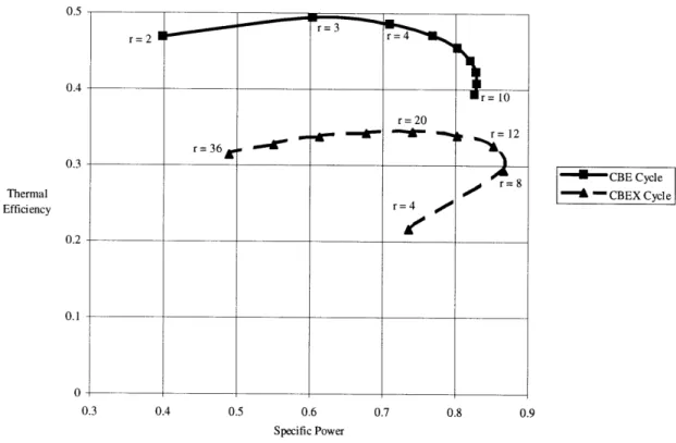
Figure 1.3 Plots of thermal efficiency versus specific power for simple cycle, CBE, and regenerative cycle, CBEX, with different pressure ratios, r. Figure 1.4 Consequence of changing regenerator effectiveness on thermal efficiency and specific power for a fixed turbine-inlet temperature ... 32
Figure 1.5 Consequence of changing cycle pressure drop on thermal efficiency and specific power for a fixed turbine-inlet temperature. ... ... 33
Figure 1.6 Consequence of changing regenerator seal leakage on thermal efficiency and specific power for a fixed turbine-inlet temperature ... 34
Figure 1.7 Cross-sectional view of a rotary regenerator. ... 35
Figure 1.8 Relocation of sealing distances for an annular matrix... 37
Figure 1.9 General arrangement of a modular regenerator... ... 38
Figure 1.10 Cross-sectional view of a drum regenerator... ... 39
Figure 2.1 General layout of the module-seal concept with a seal length of one module. 44 Figure 2.2 Module-seal concept with a seal length of two modules. ... 45
Figure 2.3 General layout of the gate-seal concept with a chamber length of one module length. ... 46
Figure 2.4 Gate-seal concept with a chamber length of two module lengths. ... 47
Figure 3.1 Representation of a typical ceramic module... 52
Figure 3.2 Representation of typical rim and matrix components that comprise a ceramic m odule. ... 53
Figure 3.3 Ceramic matrix with rectangular passages with relevant dimensions. ... 55
Figure 4.1 Design drawing of overall configuration... ... 61
Figure 4.2 Design drawing of overall configuration without casing cover ... 62
Figure 4.3 Design drawing of regenerator casing including the covers... 63
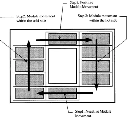
Figure 4.4 Example of module movement on the cold side ... . 64
Figure 4.5 Diagram of the four-step one-module-movement cycle when one module void exists. ... 65
Figure 4.6 Diagram of the two-step one-module-movement cycle when two module voids exists. ... 66
Figure 4.7 Diagram of the sub-steps used in two-step module movement ... 67
Figure 4.8 Channel-geometry option A where both sides have the same channel length.. 68
Figure 4.9 Channel-geometry option B where both sides have the same channel width... 68
Figure 4.10 Typical pneumatic/hydraulic double-acting cylinder used for module movement including a cross-sectional view. ... ... 71
Figure 4.11 Accommodation in the regenerator casing for the cylinder rod end... 73 Figure 4.12 Module and cylinder-rod movement sequence for cylinder configuration #1.75
Figure 4.13 Cylinder configuration #2 for step 1 module movement... 77
Figure 4.14 Module and cylinder-rod movement sequence for cylinder configuration #2.78 Figure 4.15 Module-movement mechanisms for regenerator orientation #1 ... 80
Figure 4.16 Module and cylinder-rod movement sequence for regenerator orientation # 1 ... ... . . . 8 1 Figure 4.17 Module and cylinder-rod movement sequence for regenerator orientation #2 ... ... 82
Figure 4.18 Air flow with the air-transfer ducting during step 1 module movement... 83
Figure 4.19 Air flow with the air-transfer ducting during step2 module movement... 84
Figure 4.20 Air-transfer ducting incorporated into the regenerator casing. ... 85
Figure 4.21 Diagram of how the modules within the seals can move into the hot side due to the net pressure forces ... 86
Figure 4.22 Module-Retention Mechanism ... ... 88
Figure 4.23 Seal section for the module-seal concept ... 90
Figure 4.24 Module replacement during regenerator operation. ... 92
Figure 5.1 Regenerator D im ensions... 96
Figure 5.2 M odule Dim ensions ... 96
Figure 5.3 Representation of a one passage matrix ... 110
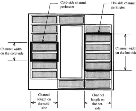
Figure 5.4 Channel configuration for one side of the regenerator showing the channel perimeter and the exposed matrix and rims... 119
Figure 5.5 Module-movement time tree ... 127
Figure 5.6 Free-body diagrams for module-movement step 1l, configuration #1... 132
Figure 5.7 Free-body diagrams for module-movement step 1l, configuration #2... 133
Figure 5.8 Free-body diagram for module-movement step2, orientation #1. ... 133
Figure 5.9 Free-body diagram for module-movement step2, orientation #2. ... 134
Figure 5.10 Effect of changing the pressure ratio on cycle thermal efficiency. ... 155
Figure 5.11 Effect of changing the pressure ratio on gas-turbine work output. ... 155
Figure 5.12 Effect of changing the pressure ratio on gas-turbine specific power... 156
Figure 5.13 Effect of changing the pressure ratio on the power required by the regenerator to move the modules... 156
Figure 5.14 Effect of changing the gas-turbine mass-flow rate on the gas-turbine work output... ... ... ... 157
Figure 5.15 Effect of changing the gas-turbine mass-flow rate on the module width and len g th . ... . ... . 15 8 Figure 5.16 Effect of changing the gas-turbine mass-flow rate on the regenerator mass. 158 Figure 5.17 Effect of changing the gas-turbine mass-flow rate on the power required by the regenerator to move the modules. ... 159
Figure 5.18 Effect of changing the regenerator effectiveness on the cycle thermal efficiency. ... ... 16 1 Figure 5.19 Effect of changing the ceramic-matrix passage aspect ratio on the matrix passage density ... .. ... . .... . ... ... 162
Figure 5.20 Effect of changing the ceramic-matrix passage aspect ratio on the thickness of the module/matrix ... ... 162
List of Figures 15
Figure 5.21 Effect of changing the ceramic-matrix passage aspect ratio on the face area for
one side (hot or cold) of the regenerator. ... 163
Figure 5.22 Effect of changing the ceramic-matrix passage aspect ratio on the module length. ... 163
Figure 5.23 Effect of changing the ceramic-matrix passage aspect ratio on the module width. ... 164
Figure 5.24 Effect of changing the ceramic-matrix passage aspect ratio on the module m ass. ... 164
Figure 5.25 Effect of changing the ceramic-matrix passage aspect ratio on the regenerator m ass. ... 165
Figure 5.26 Effect of changing the ceramic-matrix passage aspect ratio on the total time for movement of one module. ... 165
Figure 5.27 Effect of changing the ceramic-matrix passage aspect ratio on the power required by the regenerator to move the modules ... 166
Figure 5.28 Effect of changing the ceramic-matrix hydraulic diameter on the thickness of the m odule/m atrix ... . 167
Figure 5.29 Effect of changing the ceramic-matrix hydraulic diameter on the matrix passage density ... 167
Figure 5.30 Effect of changing the ceramic-matrix hydraulic diameter on the axial-conduction param eter. ... ... 168
Figure 5.31 Effect of changing the ceramic-matrix hydraulic diameter on the module m ass. ... 168
Figure 5.32 Effect of changing the ceramic-matrix hydraulic diameter on the total time for m ovem ent of one m odule ... ... 169
Figure 5.33 Effect of changing the ceramic-matrix hydraulic diameter on the power required by the regenerator to move the modules ... 169
Figure 5.34 Effect of changing the matrix porosity on the face area for one side of the regenerator ... 170
Figure 5.35 Effect of changing the matrix porosity on the matrix passage density... 171
Figure 5.36 Effect of changing the matrix porosity on the axial-conduction parameter. 171 Figure 5.37 Effect of changing the matrix porosity on the module length. ... 172
Figure 5.38 Effect of changing the matrix porosity on the module width. ... 172
Figure 5.39 Effect of changing the matrix porosity on the module mass. ... 173
Figure 5.40 Effect of changing the matrix porosity on the regenerator mass ... 173
Figure 5.41 Effect of changing the matrix porosity on the total time for movement of one m odule. ... 174
Figure 5.42 Effect of changing the matrix porosity on the power required by the regenerator to move the modules ... 174
Figure 5.43 Effect of changing the regenerator face-area ratio on the pressure drop for the cold side. ... 176
Figure 5.44 Effect of changing the regenerator face-area ratio on the regenerator face areas ... ... 176
Figure 5.45 Effect of changing the regenerator face-area ratio on the thickness of the
module/matrix. ... 177
Figure 5.46 Effect of changing the regenerator face-area ratio on the volume of the core m atrix ... ... 177 Figure 5.47 Effect of changing the regenerator face-area ratio on the module length.... 178 Figure 5.48 Effect of changing the regenerator face-area ratio on the module width... 178 Figure 5.49 Effect of changing the regenerator face-area ratio on the module mass... 179 Figure 5.50 Effect of changing the regenerator face-area ratio on the regenerator mass. 179 Figure 5.51 Effect of changing the regenerator face-area ratio on the total time for
m ovem ent of one m odule ... 180 Figure 5.52 Effect of changing the regenerator face-area ratio on the power required by
the regenerator to move the modules. ... 180 Figure 5.53 Effect of changing the cold-side number of modules on the module length. 181 Figure 5.54 Effect of changing the cold-side number of modules on the module width. 182 Figure 5.55 Effect of changing the cold-side number of modules on the module mass. . 182 Figure 5.56 Effect of changing the cold-side number of modules on the regenerator
m ass .. ... . . 183 Figure 5.57 Effect of changing the cold-side number of modules on the total time for
m ovem ent of one m odule... 183 Figure 5.58 Effect of changing the cold-side number of modules on the power required by
the regenerator to move the modules. ... 184
Figure 5.59 Effect of changing the percentage of time spent for step l on the power
required by the regenerator to move the modules ... 185 Figure 5.60 Effect of minimum required cylinder-bore diameter for step 1 module
m ovem ent ... 192 Figure 5.61 Effect of minimum required cylinder-bore diameter for step2 module
m ovem ent ... 193 Figure 5.62 Comparison of sealing distances for rotary and modular regenerators ... 195 Figure 5.63 Location of module faces where the leakage occurs. ... 196 Figure 5.64 Diagram of seal along the module front and back faces showing relevant
dim ensions ... 199 Figure 5.65 Diagram of seal along the module top and bottom faces showing relevant
dim ensions... ... ... 199 Figure 5.66 Predicted net seal leakage from the high-pressure side of the regenerator
based on the design results for the module seal concept... 207 Figure 5.67 Predicted net seal leakage from the high-pressure side of the regenerator for
the gate-seal concept . ... 210 Figure 5.68 Predicted net seal leakage from the high-pressure side of a rotary regenerator
with continuous and discontinuous rotation... 211 Figure 5.69 Predicted pressure gradient within the seal for positive module movement
along the front face... 215 Figure 5.70 Predicted pressure gradient within the seal for positive module movement
List of Figures 17
Figure 5.71 Predicted pressure gradient within the seal for negative module movement along the front face... ... 2 16 Figure 5.72 Predicted pressure gradient within the seal for negative module movement
along the back face. ... 216 Figure 5.73 Predicted pressure gradient within the seal along all top and bottom module
faces (including positive and negative module movement) ... 217 Figure 5.74 Effect of changing the cold-side number of modules on the sealing
distance. ... 2 19 Figure 5.75 Effect of changing the cold-side number of modules on the total seal
leakage. ... 220 Figure 5.76 Diagram of the channel-seal concept for the gate-seal regenerator with two
seal channels ... 221 Figure 5.77 Diagram of the module-seal regenerator with a seal channel for leakage
reduction. ... 222 Figure 5.78 Diagram of the seals along the top and bottom module faces for the
List of Tables
Table 5.1 Specified gas-turbine engine parameters ... ... 98
Table 5.2 Designated required regenerator-performance parameters. ... 100
Table 5.3 Designated required regenerator-matrix parameters... 101
Table 5.4 Designated required regenerator-configuration parameters ... 102
Table 5.5 Gas turbine engine specifications ... 150
Table 5.6 Regenerator-performance specifications ... 151
Table 5.7 Regenerator-matrix specifications. ... 152
Table 5.8 Regenerator-configuration specifications ... 153
Table 5.9 Results of the gas-turbine cycle calculations ... 188
Table 5.10 Results of the calculations specifying the mean properties for both sides of the regenerator ... ... 188
Table 5.11 Results of the basic regenerator calculations ... 189
Nomenclature
Roman-Letter Symbols
a acceleration, m/sec2
Af face area, m2
Aff free face area, m2
Ah heat-transfer area, m2
AR aspect ratio
As matrix material area available for heat conduction, m2
As' heat-conduction available-area ratio
C fluid velocity, m/s
C mean fluid velocity, m/s
C, coefficient of friction
cp - specific heat at constant pressure, J/kg-K
p - mean specific heat at constant pressure, J/kg-K
Crat ( hp )min/(T p )max (heat-capacity-rate ratio)
Cro t (/h/ Cp)mat/( t/ Ep)min
d diameter, m
dh hydraulic diameter, m
dist distance or length, m
dmod distance traveled during actual module movement, m
F Force, N
FAR matrix face-area ratio
g = gravitational acceleration, m/s2
h, heat-transfer coefficient, W/m2-K
(hAh) conductance ratio
k thermal conductivity, W/m-K
1 length, m
m mass, kg
th mass-flow rate, kg/s
n number of throttlings in labyrinth seal
Nmod number of modules
NTU number of transfer units
Nu Nusselt number
P pressure, Pa
P mean pressure, Pa
Pfeed feed pressure of pneumatic cylinder, Pa
Pr Prandtl number
q incompressible dynamic pressure, Pa
S- heat-transfer rate, W
r compressor pressure ratio
R universal gas constant, J/kg-K
Re (pCdh)/g (Reynolds number)
s displacement, m
SC seal coverage
St Stanton number
t - time, s
tnet total time, s
T = temperature, K
Nomenclature 23
th thickness, m
tmod time for actual module movement, s
U overall heat-transfer coefficient, W/m2-K
v velocity, m/s v mean velocity, m/s V volume, m3 w width, m W/ - power, W W = average power, W i ' - specific power
W - normalized power requirement
x distance in the x-direction, m
Z number of passages
Greek Letter Symbols
c - flow coefficient
AP pressure drop, Pa
E regenerator effectiveness
S- effectiveness estimate (calculated)
-~ , iJ - axial-conduction-and-seal-width effect
gmat - proportion of channel area occupied by ceramic matrix
7 - Egli's carry-over factor
Trpoly total-to-total polytropic efficiency
Tlthermal thermal efficiency
S- axial-conduction parameter
- mean viscosity, kg/m-s
- coefficient of static friction
= time proportion - density, kg/m3 - mean density, kg/m3 - shear stress, Pa -- porosity Roman-Letter 1 1-2 2 3 3-4 4 4-5 5 6 acsw -air = back = bottom carry-over cer = channel chamber -cold Subscripts
station 1 in gas turbine engine
associated with the compressor station 2 in gas turbine engine
station 3 in gas turbine engine associated with the combustor
station 4 in gas turbine engine associated with the turbine
station 5 in gas turbine engine station 6 in gas turbine engine
calculated assuming axial conduction and finite seal width associated with the air flow through the gas turbine associated with the back face of a module
associated with the bottom face a module associated with carry-over leakage
associated with the ceramic material of the regenerator
associated with the regenerator channel (header/regenerator interface) associated with the seal chamber for the gate-seal concept
configl config2 cycle decel exposed extension f fillets friction front fuel gap general GT high hot i leak low mat max min mod movement nc neg net Nomenclature 25
associated with cylinder configuration #1
associated with cylinder configuration #2 associated with the overall gas-turbine cycle
associated with the module-movement deceleration device
associated with exposed to the flow
associated with the cylinder-rod extension stroke associate with an final condition
associated with fillets along the module edges associated with friction
associated with the front face of a module
associated with the gas-turbine engine fuel
associated with leakage through the seal-clearance gap associated with a general or generic term
associated with the gas-turbine engine
associated with the high-pressure cold side of the regenerator
associated with the hot side of the regenerator associate with an initial condition
associated with the regenerator seal leakage
associated with the low-pressure hot side of the regenerator associated with the ceramic-honeycomb regenerator matrix maximum
minimum
associated with a module
associated with module movement calculated assuming no axial conduction associated with negative module movement associated with a net or total result
orient] associated with regenerator orientation #1 orient2 associated with regenerator orientation #2 pass associated with the ceramic matrix passages
pos associated with positive module movement
pressure associated with fluid pressure
regenerator associate with the modular regenerator
retraction associated with the cylinder-rod retraction stroke
rim associated with the module rim
rod associated with the cylinder piston rod
seal associated with the labyrinth seal along a module face
seal-channel- associated with the seal-channel concept for leakage reduction side associated with the side face of a module
slots associated with slots in the module rim step associated with a module movement step
stepl associated with step 1 of module movement
step2 - associated with step2 of module movement
top associated with the top face of a module
unexposed - associated with being not exposed to the flow
1.
Introduction
Regenerators are heat exchangers which can be used to improve the thermal efficiency of gas-turbine engines. Most regenerator concepts have intrinsic compressed-air-leakage problems which lower an engine's thermal efficiency. Wilson and MIT have patented a new regenerator concept [1] that promises to offer substantially less leakage than current designs. The work presented is a design study for this concept called the modular regenerator. This chapter provides some fundamental aspects of regenerative gas-turbine cycles and regenerator performance. In addition, the different types of regenerators are introduced. In the next chapter, variations of the modular-regenerator concept are described. Thereafter, a detailed mechanical description is given. Finally, methods to design a modular regenerator and determine its heat-transfer and fluid-mechanical performance are presented.
1.1
Gas-Turbine Regenerative Cycle
The simple gas-turbine cycle consists of a compressor, combustor (also called a burner), and turbine. Air first enters the compressor where it is compressed, then fuel is
added and burned with the air in the combustor, thus increasing the energy of the mixture. The combustion products enter the turbine where the energy is extracted to drive the
compressor and any external equipment. Upon exiting the turbine, the gas is released to the atmosphere. The exhaust temperature is relatively high; therefore, the thermal energy associated with the exhaust is wasted. Regenerators are used to recover some of this energy by reintroducing it back into the cycle just prior to combustion (hence the term "regeneration"). The compressed air now enters the combustor at a higher temperature, so less fuel is needed for the same amount of energy output. The result is an increase in thermal efficiency, which is defined as the work output divided by the heat input. The regenerative process can be represented on a temperature-entropy diagram as shown below with corresponding stations placed on the regenerative gas-turbine block diagram in Figure 1.2.
I
4 a) H a) -H)Entropy, S
Regenerators 29 Compressor Turbine 2 3 4 Combustor 6 5 Heat Exchanger
Figure 1.2 Block diagram of regenerative gas-turbine engine.
1.2
Regenerators
1.2.1 Regenerator Performance
This section discusses the fundamental performance aspects associated with regenerators. The performance plots shown in this section are based on the specified engine parameters from the design analysis of Chapter 5. The equations used to generate the performance curves are found in Section 5.2.2.3.4. Note that all plots are made with different pressure ratios, r, and the turbine-inlet temperature is fixed.
Cycle Comparison
As previously mentioned, regenerators increase the cycle thermal efficiency. This can be illustrated with the following figure which plots thermal efficiency versus specific power (a dimensionless gas-turbine power output) for two cycles. CBE is the simple cycle
burner, turbine, heat exchanger). Note that the CBEX curve has the regenerator effectiveness equal to 0.95. Thermal Efficiency 0.3 0.4 0.5 0.6 Specific Power " CBE Cycle - CBEX Cycle 0.7 0.8 0.9
Figure 1.3 Plots of thermal efficiency versus
and regenerative cycle, CBEX.
specific power for simple cycle, CBE,
The figure shows that the regenerator increases the thermal efficiency
approximately by 40 percent. Furthermore, with the introduction of a regenerator, the optimum compressor pressure ratio (where the thermal efficiency peaks) is much lower. From the plot, the thermal efficiency peaks at r=20 for CBE and at r=-3 for CBEX. Operating at a lower pressure ratio has several benefits: reducing compressor blades stresses, increasing compressor efficiency because blade tip-clearance effects are reduced (since longer blade usage is allowed due to the lower air density), reducing losses since the compressor air flow can travel at subsonic speeds, and increasing the part-load efficiency [2]. r= 2 '= 3 r--4' r= 10 r= 20 r=36, w r = r=8
1(
I,Regenerators 31
Effectiveness
Effectiveness is a measure of the regenerator's thermal performance. Effectiveness is defined as the ratio of the actual heat transfer that occurs divided by the maximum possible amount of heat transfer. This can be written for a regenerative cycle as
m( )cold (T3 -2)
E = (1.1) (h )min (T,- '2) or(
)hot (T
-1.2
( O )min(5;
-72)Limits do not exist (100 percent is the absolute limit) for effectiveness but the
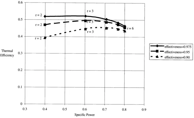
regenerator's size will increase as effectiveness increases [2]. Increasing effectiveness has several advantages which can be shown graphically in the next plot.
r= 3 r = 2 IP- L -1 r=2 6-r=3 r=2 S effectiveness-0.975 - effectiveness-0.95 " " effectiveness-0.90 0.3 0.4 0.5 0.6 Specific Power 0.8 0.9
Figure 1.4 Consequence of changing regenerator effectiveness on thermal efficiency and specific power for a fixed turbine-inlet temperature.
Thus, when effectiveness increases, thermal efficiency increases (by a greater factor at pressure ratios), and the optimum compressor pressure ratio is decreased. Therefore, high-effectiveness regenerators are quite desirable.
Pressure Drop
A pressure drop occurs as the fluid flows through a regenerator and its ducting
because of fluid friction. The larger the pressure drop, the more power required to move the fluid. The pressure drop can be controlled by changing the fluid velocities and the regenerator-passage areas. Other components of the gas turbine have pressure losses such as the combustor. The total pressure drop over a cycle is the sum of all component
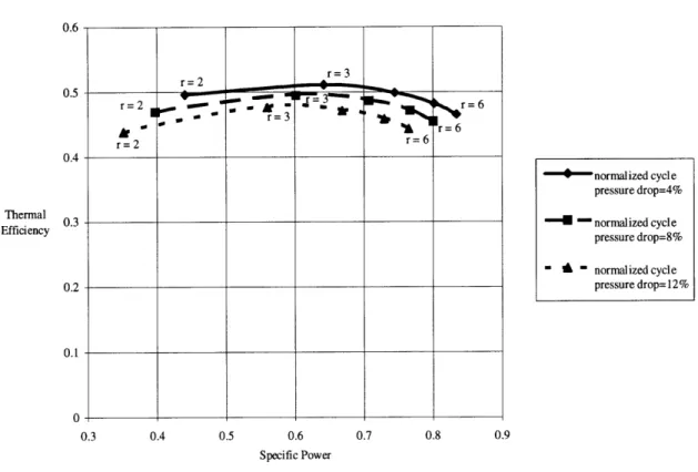
pressure drops and will influence the thermal efficiency as shown in the next figure.
r=2 0.5 0.4 Thermal Efficiency 0.2 0.1 0 " I rIr=
Regenerators 33 0.6 0.5 0.4 Thermal 03 Efficiency 0.2 0.1 0 0.3 0.4 0.5 0.6 Specific Power - normalized cycle pressure drop=4% " - normalized cycle pressure drop=8% " - normalized cycle pressure drop= 12% 0.8 0.9
Figure 1.5 Consequence of changing cycle pressure drop
specific power for a fixed turbine-inlet temperature.
on thermal efficiency and
As the cycle pressure drop increases, the thermal efficiency and specific power decreases for a given pressure ratio. More power is required to overcome the pressure drop resulting in less power output and thus, a lower thermal efficiency. Since the
regenerator pressure drops contribute to the cycle pressure drop, they should be kept low.
Leakage
A problem with regenerators is the leakage of compressed air along the seals.
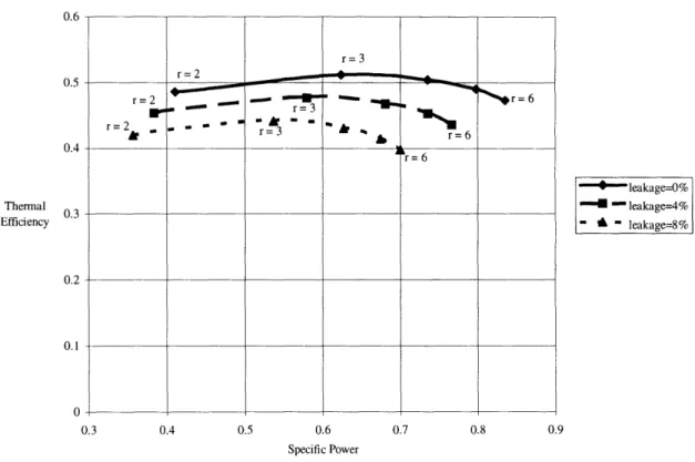
Some 4-14 percent of the compressor mass flow escapes for typical regenerator designs [2]. A high leakage rate has detrimental effects on gas-turbine performance as illustrated in the following figure.
r=3 r= 2 =_ 2 rft, " 7 " Ir=6 sr 2r= 6 r= 2 r=6
0.6 0.5 0.4 Thermal Efficiency 0.2 0.1 0 1 0.3 0.4 0.5 0.6 Specific Power -*-- leakage-0% S- leakage=4% - " leakage=8% 0.7 0.8 0.9
Figure 1.6 Consequence of changing regenerator seal
and specific power for a fixed turbine-inlet temperature.
leakage on thermal efficiency
As the leakage increases, drops in both thermal efficiency and specific power occur. As the compressor pressure ratio increases, leakage rates increase and reductions in thermal efficiency and specific power are more evident. Thus, the seal leakage should be reduced as much as possible to minimize such performance drops. Unlike effectiveness and pressure drop, leakage rates cannot easily be adjusted by changing some design parameters since much of the leakage is inherent to the design. This was the motivation in developing the modular regenerator.
1.2.2 Regenerator Concepts
The regenerators described in this section are termed periodic-flow heat exchangers because they consist of a heat-transfer surface (ceramic material containing small passages in a honeycomb arrangement called a matrix) that is periodically transferred
r=3 r= 2 r=2 r=3 r=6 r=2 . . . . - , , r=3 r=6 r= 6
Regenerators 35
from the cold compressed-air flow to the hot exhaust flow. On the hot side, heat is transferred from the exhaust gases to the ceramic material as it flows through the
passages. On the cold side, heat is transferred from the matrix material to the compressed-air flow.
1.2.2.1 Rotary Regenerators
Typical gas-turbine regenerators are rotary types which consist of a ceramic matrix disk. The hot exhaust flows through part of the disk and the cold compressed air flows through the rest in the opposite direction. This is shown in the following figure taken from Bathie [3]. The disk is rotated such that the hot portion is then exposed to the cold side and vice versa. Despite using a matrix with small passages, the passage blockage from exhaust particles is usually not a problem since the flow directions are reversed between the two streams. So any exhaust contaminants stuck in a passage are pushed out as the passage moves to the cold side. These particles then are burned up in the combustion chamber. Cold Compressed-Air Flow SHot Exhaust Flow
I
1.2.2.1.1 Continuous-Rotation Regenerators
Continuous-rotation regenerators rotate at a constant rate to give a desired temperature distribution within the matrix. Face seals exist on both sides of the disk along the inner and outer circumference and along two radii to separate the compressed-air flow, exhaust-gas flow, and the surrounding atmosphere. The seals are pressed upon the matrix to minimized the leakage. As the disk rotates over time, the seals and matrix wear down which normally results in higher leakage rates. Current designs have yet to maintain seal leakage at acceptable levels over time.
1.2.2.1.2 Discontinuous-Rotation Regenerators
In addition to the patent for the modular regenerator, Wilson and MIT [1] have patented a sealing concept that reduces the seal leakage associated with rotary
regenerators. This concept consists of rotating the matrix disk discontinuously. The face seals lift up by a small distance during matrix rotation over a finite angle (such as 30 degrees), then clamp down until the next rotation. This provides essentially zero leakage between rotations. The net result is a significant reduction in leakage and seal wear. Discontinuous-rotating regenerators have been investigated by Beck [4] and Pfahnl [5].
1.2.2.2 Modular Regenerators
This section gives the rationale made by Wilson [6] on how the modular-regenerator concept was conceived. Rotary concepts have long sealing distances
(transverse length of the seals along the periphery of the high-pressure side). Reducing the sealing distance will reduce the leakage. Most of the leakage occurs over the radial seals. The radial sealing distance can be reduced by increasing the inner radius of the disk forming an annular matrix. The seals can then be relocated to encompass the cross-sectional area of the matrix, thus reducing the sealing distances considerably. The relocated seals are illustrated in the figure below.
Regenerators 37
Typical Sealing Distance (on both sides of matrix)
New Sealing Distance
Hot Exhaust Flow Hot Exhaust Flow
.
.
Cold Compressed-Air Flow Cold Compressed-Air Flow
Figure 1.8 Relocation of sealing distances for an annular matrix.
Then the matrix can be broken up into smaller segments (called modules) and straightened to form blocks with rectangular flow passages as shown in the next figure. The modules are moved linearly within the passages such that modules exposed to one
flow are moved to the other exposed area. A space of at least the volume of one module is needed to allow movement. In addition, the two exposed areas could be separated further than as shown below to eliminate any special ducting of the flow. The modular concept is also self-cleaning since the flow directions are reversed. Furthermore, removal of modules (that are not located within the exposed areas) from the regenerator for periodic
maintenance or replacement is possible. This can be performed during regenerator operation which is not feasible with any other regenerator concepts.
Sealing Distance \ Module Area exposed to cold-side flow Cold Compressed- / Air Flow
.LI..IIZ..Z
..
W - N'LZ...h..
[~1m.
Hot Exhaust Flow
SArea exposed to
hot-side flow
%- Sealing Distance
Figure 1.9 General arrangement of a modular regenerator.
Since the total sealing distance has dramatically decreased, the seal leakage should be much lower than conventional rotary types. The major consequence in making the transition to the modular case is an increase in mechanical complexity. Several devices, such as linear actuators, will be required for module movement.
1.2.2.3 Other Types
Other regenerator concepts exist but are not as commonly used. One example is the rotating drum which consists of the matrix in a cylindrical configuration, where the matrix is rotated along the cylinder axis. A cross section of a drum regenerator is shown below taken from Bathie [3]. Another regenerator type is the valved regenerator. This concept has a stationary matrix with valves that allow the matrix to be exposed to each stream periodically. Since these concepts are not as prevalent, they are not included in any comparative studies with modular designs.
Regenerator Applications 39
Cold Compressed-Air Flow
Hot Exhaust Flow
Figure 1.10 Cross-sectional view of a drum regenerator.
1.3
Regenerator Applications
1.3.1 Rotary
Rotary regenerators have been designed primarily for vehicular applications. The regenerator allows the gas-turbine to have high thermal efficiency at full and part load which is required for vehicular use. Many of the larger automobile manufacturers have developed experimental vehicles with regenerative gas-turbine engines in the past 30 years.
The size of the monolithic ceramic matrix disk is limited to a diameter of 1 m due to manufacturing and thermal-stress constraints [6]. Therefore, applications to larger gas-turbine engines are not generally possible.
1.3.2 Modular
Breaking up the matrix into modules allows the exposed flow areas to have
virtually unlimited size. If a larger area is needed, the designer can just add more modules. In addition, two separate modular regenerators could be used when larger heat-transfer areas are required. This makes modular regenerators suitable for ground-based gas
turbines used in industrial power-generation units. Furthermore, the modular concept could be used in exhausted-heated cycles to burn coal, wood, and refused-derived fuels as proposed by Wilson [7]. These cycles burn "dirty" fuels in which combustion products can clog the matrix passages despite the inherent self cleaning of the matrix. Having the
capability to replace the modules for cleaning during continuous engine operation makes the modular case attractive.
When competing with rotary applications, a modular regenerator's size might preclude their use on some small gas-turbine vehicles. The overall dimensions will be considerable greater than rotary designs due to the open space between the two sides. The size might be too large to fit in a vehicle's engine compartment. Furthermore, additional analysis is needed show that module movement can withstand the vehicular environment.
Finally, Wilson states that regenerator designs would require very low leakage at pressure ratios of 8:1 for aircraft-engine applications [6]. Rotary concepts have been unsuccessful thus far to provide this, but modular concepts (and discontinuous-rotation concepts) might be able to achieve such performance.
1.4
Conventions and Terminology
The following are some conventions and terms used throughout this study: * The fluid flowing through stations 1 to 3 is called "air" since it is just the ambient air
undergoing compression and heat addition. The fluid flowing through stations 3 to 6 is called a "gas" since it contains air, unburned fuel, and combustion products.
* The compressed air travels through the regenerator from station 2 to 3. This is called the cold or high-pressure side.
* The exhaust gas travels through the regenerator from station 5 to 6. This is called the hot or low-pressure side.
Summary 41
* The terms "core", "matrix", and "core matrix" are used interchangeably to represent the ceramic-honeycomb matrix material.
* When assigning dimensions to regenerator objects in 2-D, generally, the terms
"length" and "width" refer to the longer and shorter dimensions respectively. There is one exception to this convention. This occurs when defining the channel areas in Section 4.2.2.3.
* For all modular configurations, the cold side is located on the left with the flow going into the paper, and the hot side is on the right with the flow going out of the paper. The seals are located between the two sides.
* Module movement occurs in a clockwise direction.
* Sealing distance refers to the transverse length of the seal where leakage can occur. Seal length refers to the longitudinal length of the seal in the direction of leakage flow. This is not a standard nomenclature convention when describing regenerator seals. Typically, "sealing distance" is referred as "sealing length." The convention used is made to eliminate any possible confusion between the two seal parameters.
1.5
Summary
Modular regenerators should provide less leakage than other designs due to a large reduction in sealing distance. Nevertheless, this type of heat-exchanger is more
mechanically complex since several devices are needed to move the modules. By separating the matrix into rectangular entities, the range of regenerator applications is increased because larger matrix sizes are conceivable. The following chapters are devoted for additional design descriptions along with design and performance calculations.
2.
Modular Regenerators
2.1
Introduction
The section presents the various modular concepts. Basically, two different types exist. Both concepts are similar except in the type of sealing technique used. The first concept has a module acting as the seal. The second uses partitions to seal off the compressed air.
2.2
Modular Concepts
Module-Seal Concept 2.2.1
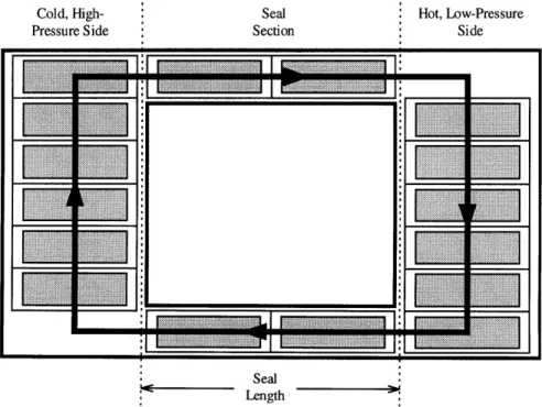
The module-seal concept consists of separating the hot and cold sides with two rectangular passages containing seals that are surrounding the modules located within these passages. This passage area is called the seal section. The modules must always be present in the seal section to seal off the high-pressure air. The following figure illustrates
the general layout. This concept provides the simplest modular configuration from a mechanical standpoint.
With the short sealing distances and the long seal length, this option should provide very low leakage. The seal length could be increased as shown in Figure 2.2. Increasing the seal length could also reduce any special ducting of the flow. Consequently, as the seal length gets larger, the time for a module to travel from one side to the other will increase (if the speed of the modules remains constant). This may cause a reduction in effectiveness due to heat conduction within the matrix material. Such effects are analyzed in Chapter 5.
The large pressure forces must be accounted for on the modules located within the seal section. These forces push the modules toward the low-pressure side. This will be advantageous for modules traveling in the direction of the pressure force; however, these forces must be overcome when modules are traveling towards the high-pressure side. Several mechanisms could be used to move the modules through the seal section and within the hot and cold sides. Detailed techniques on the methods chosen for module movement are described in Section 4.2.
Modular Concepts Seal Section Seal Hot, Low-Pressure Side Module Movement Path Module Seal Length
Figure 2.1 General layout of the module-seal concept with a seal length of one module. Hot, Low-Pressure Side I ~~~'~a Ii ~i~l II
LI
L
.[[;jI
[13...
E
li:::::::::::::::
L
I:::::::::::::::
z
z
El
111
Il
* L i.I-II:f Seal LengthFigure 2.2 Module-seal concept with a seal length of two modules.
Cold, High-Pressure Side Cold, High-Pressure Side Seal Section ,° m .. .... . .. .. . .. .. . . ... .. ... .. ... .
2.2.2 Gate-Seal Concept
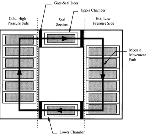
Wilson's first proposal for sealing the modules in the regenerator was to partition the hot side, cold side, and seal section using gate-seal doors (also called gate valves) [1]. These doors open and close to allow module movement. This concept is termed the gate-seal concept. The basic layout has the gate-seal section containing two chambers with gate-gate-seal doors on either side. The general arrangement is shown in the next figure. Module
movement through a seal section occurs when one of the two gate-seal doors opens for each chamber, thus letting modules in and out. This movement scheme is described in more detail in Section 4.3.
For this concept, the leakage consists of the transfer of compressed air when the door opens to the low-pressure side. This differs for each chamber where the upper chamber has less leakage than the lower chamber. This occurs because the upper-chamber door on the right opens to move a module out of the chamber to the low-pressure side, and the lower-chamber right door opens to let a module enter. Thus, part of the upper chamber's volume is occupied by a module, and the rest is air that is transferred as leakage. For the other chamber, it is empty as the right door opens, therefore, the entire volume of air within the chamber is transferred as leakage.
Mechanisms are require to move the modules within the hot and cold sides and in and out of each chamber. This concept will probably require more mechanisms than the module-seal concept because more steps are made during module movement (with the addition of the gate-seal doors). Furthermore, like the module-seal concept, the gate-seal regenerators can have a longer seal section by adding more chambers as shown in Figure 2.4.
Modular Concepts 47 Gate-Seal Door SModule Movement Path Lower Chamber
Figure 2.3 General layout of the gate-seal concept with a chamber length of one module length.
Cold, High-Pressure Side Hot, Low-Pressure Side Seal Section
Figure 2.4 Gate-seal concept with a chamber length of two module lengths.
2.3
Summary and Conclusions
Two modular concepts were presented: the module-seal concept and the gate-seal concept. These concepts reduce the sealing distances for leakage reduction. The seal concept is the simplest concept and should require the least amount of module-movement devices. Since modular regenerators have additional mechanical complexity than rotary regenerators, a logical step is to design a modular regenerator with the least complex concept. Therefore, the majority of the mechanical design and analysis will focus on the module-seal concept.
:11
~~7TET7777z
~~ ii z.. .z
:
I
LI
I
- II...
N. a3.
Module/Matrix Design
3.1
Introduction
One major aspect of designing a modular regenerator is the design of the ceramic module. Modules have yet to be manufactured but current ceramic technology should be sufficient for preliminary development. Corning Incorporated is currently developing ceramic matrices for gas-turbine regenerators under the Automotive Turbine Technology Applications Project (ATTAP), sponsored by the U.S. Department of Energy.
Fortunately, much of their work has direct applications for module development. This section will discuss Coming's research, its applications for module development, and other aspects required for module design.
3.2
Regenerator Development at Corning
3.2.1 Summary of Research
Corning Incorporated is currently conducting research with Allison Engine Company to develop a cost-effective process for the manufacture of ceramic rotary regenerators. Their investigation concerns the development of ceramic matrix materials that are low in cost and provide adequate temperature capability, chemical durability, dimensional stability, thermal shock, stress resistance, leakage from material porosity, and strength [8].
Corning has determined that one way to reduce cost is to use extrusion as the manufacturing process. The earlier method for fabricating regenerator cores is by wrapping thin paper coated with lithium-aluminosilicate (LAS) material in a coil, a very expensive process. This technique was used on the first glass-ceramic gas-turbine regenerators in the 1960s. The process consists of applying glass and ceramic binders to two sheets of tea-bag paper. One sheet is crimped to form a sinusoidal shape and the other remains flat. The two sheets are joined and then wrapped in a spiral to form a core matrix with near-triangular passages. Then the matrix is fired and machined to become the final product. On the other hand, extrusion consists of forcing the ceramic material through dies. Afterwards, it is fired and machined. This process is considerable less expensive because Coming has been manufacturing millions of automotive catalyst supports using extrusion for the past twenty years [9].
The candidate materials first consisted of LAS, aluminosilicate (AS), magnesium-aluminosilicate (MAS), mullite-aluminum titanate (MAT), and sodium-zirconium
phosphates (NZP). MAT was dropped from the project based on initial assessments. NZP was also dropped because of extremely high cost [9]. LAS, the standard regenerator material, has been plagued with chemical durability problems in the past, and is relatively high in cost. AS, a derivative of LAS, was developed to ameliorate the LAS chemical
Regenerator Development at Coming 51
problems by refiring the material to remove the hydrogen. This additional process makes AS production more expensive than LAS. MAS materials, generally known as cordierite, is the least expensive since this material was developed for use in catalyst supports. Recently, Coming has settled on two compositions, LAS and MAS. LAS's main problem now is high cost. MAS materials that have been developed show promise in all areas except maintaining strength under thermal cycling [8]. Corning is currently testing MAS cores at Allison and investigating ways to improve the MAS strength and reduce the LAS cost.
The other aspect of Coming's work concerns extrusion-die development. Corning has been able to extrude ceramics at 170 rectangular cells per square centimeter with a diameter of 0.27 m [8]. This falls short of their 0.3 m goal, and further research is ongoing.
Work on this project will probably continue until a material developed meets all design requirements. Cordierite (MAS) appears headed towards satisfying the
requirements mainly because its hurdles are easier to overcome.
3.2.2 Applications for Module Development
Since the modules are rectangular in shape, manufacturing rectangular matrices by extrusion will obviously be a better (and cheaper) process. Therefore, the results of Coming's research should be directly applicable toward module design. Additional work will be required in developing a die for rectangular extrusions since Corning is making only circular dies. Considering the size of current dies, rectangular extrusions will probably be no larger that 0.3 m square in cross section [10].
3.3
Matrix Construction and Design
3.3.1 Matrix Materials
Based on Corning's research, extruded cordierite will be the preferred material in this design study. Even though cordierite has not met all of Corning's requirements, current compositions should be satisfactory for module prototypes.
A typical module is shown in the next figure (matrix passages are not to scale).
Notice that core matrix is surrounded by a solid rim. This gives protection to the core during module transit. The rim material should probably be composed of the same material as the matrix to avoid potential thermal-expansion problems. Nevertheless, the potential exists to use other rim materials such as metals, alloys, or composites (neglecting current temperature limitations) that have quite different thermal-expansion properties. Such possibilities exist by using a mat mount along the core/rim interface. Mat mounts such as the Carborundum Company's Expanding Paper is a material used in catalytic converters to support ceramic monoliths within steel frames. The current drawback is the limited
maximum operating temperature of 8000C. If temperatures exceed 800'C, then thermal
degradation of the material occurs [11]. Therefore, further development is required to use mat mounts with modular-regenerator applications.
Matrix Construction and Design 53
Figure 3.1 Representation of a typical ceramic module.
3.3.2 Matrix/Rim Integration
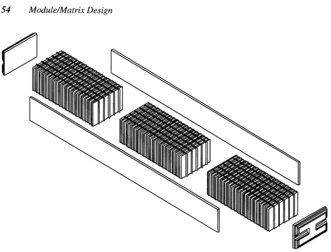
From the design results of Chapter 5, typical modules for a small gas-turbine engine will have dimensions around 0.75 m by 0.1 m. If the maximum size limit for an extruded ceramic matrix is 0.3 m square, several matrices will have to be mated to each other to form a complete module. Furthermore, these matrices will have to be integrated with the module rims. A cement will be needed at all matrix/matrix and matrix/rim
interfaces. The cement will have to maintain its bonding strength under the intense thermal environment of the regenerator. This analysis does not address this issue and is left for future work. A diagram showing the typical individual parts of a module is given below. The rim is composed of 4 parts (one for each module face) and the core is made up of 3
Figure 3.2 Representation of typical rim and matrix components that comprise a ceramic module (matrix passages are not to scale).
3.3.3 Matrix Passage Geometry
When designing the module, selecting the type of matrix passage geometry is critical since this can dictate the performance of the regenerator. When comparing the Nusselt numbers for various passage geometries for laminar flow, rectangular passages have the highest value. The Nusselt number is a non-dimensional heat-transfer coefficient; therefore, a rectangular geometry appears to be favorable choice. Furthermore, Hagler [12] concluded that the rectangular passages offer the best heat-transfer performance and recommended using such a geometry. Therefore, a rectangular geometry is preferred and
will be used throughout this design study.
The Nusselt number also increases as the passage aspect ratio so one would infer on using a high aspect ratio. The following will show that a higher aspect ratio does
Matrix Construction and Design 55
correlate to better heat-transfer performance for rectangular passages. This analysis assumes that only the passage aspect ratio is varied and all other parameters are held constant.
The passage aspect ratio is defined as
I pas
AR,,s =_-- (3.1)
where Ipass is the greater passage distance. The matrix dimensions are shown graphically in the next figure.
Matrix Passage (Void Area)
Matrix Wall
1pass
Figure 3.3 Ceramic matrix with rectangular passages with relevant dimensions.
Another parameter required when defining the geometry is the hydraulic diameter,
dh, defined as
dh = 4(cross sectional area) (3.2).
periphery
dh 4wpass 1I pass 2ARass Wpass
2 (Wpass + pass) +ARpass
(3.3).
The passage width and length can be expressed by combining the equations for hydraulic diameter and passage aspect ratio:
S= ( + ARpass )dh
Wpass 2 ARp(3.4) 2 AR
S(I+ ARpass ) dh
l =
2
2(3.5).
The heat-transfer area, Ah, is the matrix surface area available for heat transfer which is
Ah = 2(Was, + lpass) thmat Z (3.6),
where thmod is the passage length in the direction of the flow (module/matrix thickness) and Z is the number of passages. Plugging in the equations for the passage length and width simplifies to
Ah = (1 + ARpass) d, thm,,
Z
ARp,pars (3.7).
Porosity is a measure of how open the passages are in relation to the matrix. Porosity is defined by
mat
total void area
total void area + total solid area and can also can be written as