Delicate Manipulation of Irregularly-Shaped Rigid Objects
in a Stiff, Fragile Environmentby
Joseph Andrew Calzaretta
Bachelor of Science in Mechanical Engineering Massachusetts Institute of Technology (1996)
Submitted to the
Department of Mechanical Engineering
in partial fulfillment of the requirements for the degree of Master of Science in Mechanical Engineering
at the
Massachusetts Institute of Technology June, 1998
@ 1998 Massachusetts Institute of Technology
Signature of Au
Certified By
Accepted By
thor
17
S Depart~ent of Mechanical Engineering
6/
May 8, 1998Steven Dubowsky Thesis Supervisor
Ain A. Sonin Chairman, Departmental Graduate Committee MASSACHUSETTS INSTITUTE
OF TECHNOLOG"Y
AUG 041998
LIBRARIES
Delicate Manipulation of Irregularly-Shaped Rigid Objects in a Stiff, Fragile Environment
Submitted to the Department of Mechanical Engineering
on May 8, 1998, in partial fulfillment of the requirements for the degree of Master of Science in Mechanical Engineering
by
Joseph Andrew Calzaretta
Abstract
The automation of the crucible-charging portion of the CZ semiconductor production process with a robot assisted crucible-charging system (RACS) requires the
investigation of certain control issues. This thesis addresses the problem of regulating contact forces and endpoint positions in a system in which there is little or no passive compliance present in the manipulator or the environment.
In order to address the challenge of regulating delicate contact forces while in contact with a stiff, fragile and known environment, a hybrid position/force control algorithm was developed and implemented. This implementation was executed in simulation, on a test manipulator system, and finally on an AdeptOne-based laboratory demonstration system. Simulation and experimental results are presented.
In order to resolve the additional difficulty of an environment of unknown orientation, a surface orientation observer algorithm has been developed which uses current and previous wrist force sensor data to produce its estimate. This observer is used in conjunction with the control algorithm to obtain force and position control in an unknown environment. Expected behavior of this algorithm is discussed, and simulation results are presented.
Integration of this work with the laboratory demonstration system is discussed, and suggestions for future research in this area are proposed.
Thesis Supervisor: Dr. Steven Dubowsky
Acknowledgements
I would like to thank Professor Steven Dubowsky for his guidance and assistance during the past two years. I wish to thank Anthony Leier, Vivek Sujan, and Melissa Tata, for their work on this project. Thanks also to my other colleagues at the Field and Space Robotics Laboratory, especially Karl lagnemma, for general guidance and various contributions to my research.
This thesis describes research performed at the MIT Field and Space Robotics Laboratory under the sponsorship of Shin Etsu Handotai, Co., Ltd. Thanks to SEH for providing the financial support for this project.
I'd also like to thank my parents, sister, friends at MIT and around the country and world, and everyone I've ever met in my entire life.
Table of Contents
1 Introduction1.1 Background and Project Description... ... 10
1.1.1 The Laboratory Demonstration System ... ... 11
1.1.2 Control System Performance Specifications ... 12
1.1.3 Control System Key Technical Challenges ... 14
1.2 L iterature R eview ... 15
1.3 Purpose of this Thesis ... 17
1.4 O utline of this Thesis ... .18
2 Hybrid Position/Force Control Algorithms 2.1 Hybrid Position/Force Control...20
2.1.1 Division of Environment into Subspaces ... 20
2.1.2 Manipulator Dynamics and Simplifications ... 21
2.1.3 Jacobian Transpose and Jacobian Inverse Control ... 22
2.1.4 The Implemented Control Algorithms ... ... 23
2.2 Simulation of Control Algorithms...26
2.3 Sum m ary ... 30
3 Hybrid Position/Force Control Experiments 3.1 Experiments on a Puma 250 Manipulator... ... 32
3.1.1 Apparatus...32
3.1.2 Experimental Procedure - Roller and Nugget Tests ... 34
3.1.3 Experim ental Results... 36
3.1.4 Summary of Puma Experimental Results ... .... 40
3.2 Experiments on the AdeptOne Manipulator ... .... 41
3.2.1 Apparatus...41
3.2.2 Experimental Procedure - Roller and Nugget Tests ... 42
3.2.3 Experimental Results... ... ... 43
3.2.4 Summary of AdeptOne Experiments ... ... 47
3.3 Summary and Discussion of Experimental Results...49
4 Surface Estimation Algorithm 4.1 Instantaneous Measurement of Contact Surface ... 52
4.2 Uncertainty of the Instantaneous Estimate ... ... 55
4.2.1 Uncertainty due to uF... . ... 55
4.2.2 Uncertainty due to u ... 56
4.2.3 Total Uncertainty of Measured Normal Vector...58
4.3 The Surface Estimation Algorithm... ... ... 59
4.4 Expected Behavior of the Surface Estimation Algorithm... 62
4.4.1 E nd-effector H alts ... 62
4.4.2 C ontact B roken ... 63
4.4.3 V aried Sensor N oise Level ... 63
4.4.4 Varied Minimum Radius of Curvature ... 64
4.4.5 Typical Behavior...65
4.5 Possible Modifications to the Algorithm... ... 65
5 Simulation Results of Surface Estimation Algorithm 5.1 Overview of Simulation ... 67
5.2 Determination of the Normal Vector ... ... 67
5.2.1 The Contact M odel... ... ... 68
5.2.2 Sim ulation R esults ... ... 70
5.3 Integration of Estimator with Hybrid Position/Force Control ... 73
5.3.1 Overall System ... ... ... 74
5.3.2 The Control Algorithm... 74
5.3.3 Contact Model and Manipulator Dynamics... .... 75
5.3.4 Simulation Results ... ... ... 76
5.4 Sum m ary ... ... ... 78
6 Discussion & Conclusions 6.1 Summ ary of W ork ... ... ... 79
6.2 Laboratory System Integration...79
6.2.1 Interrupt-Driven Control Code Implementation ... 80
6.2.2 Robot Control Code ... 81
6.2.3 Integration with Vision/Packing Subsystem... ... 82
6.2.4 Incorporation of Gripper/Wrist Subsystem ... 82
6.3 Future Work ... 82
References Appendix A Manipulator Kinematics A. 1 The Puma 250 M anipulator ... ... 89
A.2 The Adept One Manipulator ... 91 B Material Properties Information of Silicon and Glass
B .1 Silicon Properties... ... 93 B.2 Glass Properties ... ... 93 C Material Properties Testing
C .1 Scratch T ests ... 95 C .2 Im pact T ests ... ... 95 D Wrist Control Circuitry... ... 97
List of Figures
Figure 1-1: Characteristics of a Charged Crucible... ... 10
Figure 1-2: Laboratory Demonstration System ... ... 12
Figure 1-3: RACS Control M odes ... 13
Figure 2-1: Hybrid P/F Control, J Transpose... ... 24
Figure 2-2: Hybrid P/F Control, J Inverse ... 25
Figure 2-3: Simulation M odel... ... ... 27
Figure 2-4: Block Diagram for Hybrid Control Simulation ... 28
Figure 2-5: Simulation Results, Endpoint Held Fixed After Contact ... 29
Figure 2-6: Simulation Results, Sinusoidal Motion ... ... 30
Figure 3-1: Experimental Apparatus for Puma 250 ... ... 33
Figure 3-2: The Puma 250 Manipulator ... ... 34
Figure 3-3: Puma Roller Tests ... 35
Figure 3-4: Pum a Nugget Tests ... 36
Figure 3-5: Puma Roller Test Results, Roller Held Fixed... 37
Figure 3-6: Puma Roller Test Results, Roller in Motion... .... 38
Figure 3-7: Puma Nugget Test Results, Nugget Held Fixed ... 39
Figure 3-8: Puma Nugget Test Results, Nugget in Motion ... 40
Figure 3-9: Experimental Apparatus for the AdeptOne System...42
Figure 3-10: The AdeptOne Manipulator... 43
Figure 3-11: AdeptOne Roller Test Results, Roller Held Fixed... 44
Figure 3-12: AdeptOne Roller Test Results, Roller in Motion...45
Figure 3-13: AdeptOne Nugget Results, Nugget Held Fixed ... 46
Figure 3-14: Adept Nugget Test results, Nugget in Motion ... 47
Figure 3-15: Contention Between Force and Position Integrators...49
Figure 4-1: Surface Estimation ... 53
Figure 4-2: Uncertainty Propagation due to UF...55
Figure 4-3: Uncertainty Propagation due to u, in the b Direction ... 57
Figure 4-4: Uncertainty Propagation due to u, in the c Direction...57
Figure 5-1: Block Diagram for Surface Estimation Tests ... 67
Figure 5-2: The Contact Surface ... 68
Figure 5-3: Typical Open-Loop Estimation Results ... .... 70
Figure 5-4: Results with Less Conservative Curvature Estimate ... 72
Figure 5-5: Results with No Sensor Noise...72
Figure 5-6: Results with Large Sensor Noise ... ... 73
Figure 5-7: Block Diagram for Control Using Surface Estimation ... 74
Figure 5-8: Typical Surface-Tracking Results...77
Figure 5-9: Surface Tracking Results with No Sensor Noise ... 77
Figure A-1: Puma 250 Kinematics ... 89
Figure A-2: Adept One Kinematics...91
Figure D-1: Wrist Circuit Diagram ... 97
Chapter 1
Introduction
1.1 Background and Project Description
Shin Etsu Handotai, Inc. (SEH) produces silicon wafers via the Czochralski (CZ) process (Wolf and Tauber, 1986). One stage of this process involves the loading of irregularly shaped poly-crystalline silicon nuggets into fused silica crucibles. A charged crucible is shown in Figure 1-1, (Dubowsky, 1997).
A bed layer of small nuggets is formed at the bottom of the crucible. Then, a layer of large nuggets is carefully built touching the side wall, as the middle of the crucible is filled with bulk (small and large nuggets). Finally, a crown of large nuggets is built above the top of the crucible. Important constraints in this process include protection of the crucible from damage, minimization of silicon contamination, maintaining the required charge density, and achieving an appropriate side wall nugget contact orientation.
Crown (large nuggts)
Line contacts
Wall layer with wall are
" (large nuggets) desireable
Bulk
-small and large nugyts)
F- (small nugets)
Figure 1-1: Characteristics of a Charged Crucible
Currently, the crucible charging process is performed manually. The ultimate goal of this project is to develop an automated process for packing the nuggets, known as the Robot Assisted Crucible Charging System (RACS). This shift to an automated system should facilitate larger charge densities and the use of larger crucibles in the manufacturing process.
1.1.1 The Laboratory Demonstration System
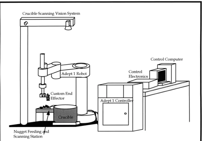
In order to achieve this goal, a laboratory demonstration system has been developed, depicted in Figure 1-2 (Dubowsky, 1997). This system is composed of three subsystems. The control system consists primarily of the AdeptOne manipulator, controller unit, control electronics, and computer running the control software. The vision/packing system contains the nugget scanning station and the overhead crucible scanner, as well as the computer which implements the packing algorithm (not shown). The grasping system consists of a custom end-effector with a three-joint wrist and a gripper. The purpose of this system is to address the important technical challenges and illustrate the feasibility of a RACS.
The automation of this process with a robot manipulator-based system presents several technical challenges. First, the RACS must be able to acquire information about the shape of a nugget to be placed and the landscape of the nuggets already in the crucible. From these data, the vision/packing system must determine the optimal location in the crucible to place the nugget so that charge density is maximized. This challenge is addressed by (Sujan, 1998). Secondly, the system end-effector must be able to grasp irregular nugget shapes and place nuggets in the crucible without contacting the crucible wall. This challenge is addressed by (Leier, 1998). Finally, the control system must be
able to delicately manipulate and place the nuggets without damaging the crucible wall or disturbing the pre-existing layer of nuggets. It is this third challenge which concerns this thesis.
Nugget Feeding d
Scanning Station
Figure 1-2: Laboratory Demonstration System
1.1.2 Control System Performance Specifications
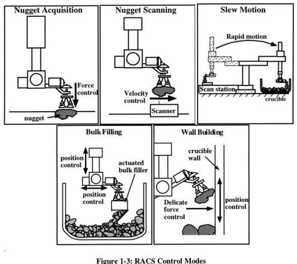
Crucible charging involves five distinct subtasks for the control system, shown in
Figure 1-3. These subtasks are nugget acquisition, nugget scanning, slew motion, wall
and crown building, and bulk filling. Certain performance specifications for the control
system were determined by the requirements for proper operation of the vision and
packing system, (Sujan, 1998), and the gripper mechanism (Leier, 1998). Performance
specifications regarding the minimization of crucible damage were determined by the
Chapter 1: Introduction 12
material properties of silicon and glass, (see Appendix B) and through experimental testing, (see Appendix C).
Figure 1-3: RACS Control Modes
In the nugget acquisition mode, the robot end-effector must grasp a nugget with the gripper. The end-effector must initially move downward at 15 cm/sec. Once contact is made and detected, the nugget is gripped. The manipulator must maintain a downward force of less than 20 N. The end-effector then moves upward at 15 cm/sec.
In the nugget scanning mode, the manipulator must pass a nugget over the nugget scanner. The end-effector is required to move horizontally at a constant speed of 3 cm/sec. The position must be regulated to within 0.5 mm.
During slew motion, the manipulator must rapidly move the nugget from the scanner to the interior of the crucible without contacting the crucible. This motion is to take place in approximately 2.5 seconds and the position must be regulated to within 1 cm for the entire motion.
In the wall building mode, the nugget must be brought against the crucible wall and lowered onto the existing layer of nuggets. The nugget is moved toward the crucible wall at no more than 10 cm/sec. Contact is made and detected. The manipulator must maintain a contact force of less than 2 N without losing contact as the nugget slides down the wall. The nugget makes contact with the existing nugget layer and must be positioned in a designated location without disturbing the existing nuggets. The manipulator releases the nugget and leaves the crucible interior. The crown building mode is similar, but it does not involve contact with the crucible wall.
In the bulk-filling mode, the manipulator must bring a bulk filler device to the interior of the crucible and release fill nuggets. The position must be regulated to within 1 cm.
1.1.3 Control System Key Technical Challenges
The wall and crown building mode is the most critical and challenging of the five control modes. The other four modes involve robotic manipulation under either pure position control or pure force control, the feasibility of which have been established previously (Craig, 1989; Whitney, 1987). The wall building process, however, requires the simultaneous positioning of a nugget while maintaining delicate contact forces. This requires another control algorithm.
When controlling contact force, it is helpful to know the surface orientation. When the contacted surface is the crucible wall, the contact surface orientation is known beforehand. An additional challenge is introduced when the nugget comes into contact with previously placed nuggets. The surface orientation of these nuggets is not necessarily known, and an algorithm must be used which can regulate force and position without a priori information.
1.2 Literature Review
Control of both contact force and endpoint position with a robot manipulator is a challenging task which has been studied by many researchers (Whitney, 1987). The two major control schemes in use today are hybrid position/force control and impedance
control.
Hybrid position/force control splits the environment into force and position control domains, and then performs conventional control in each domain (Raibert and Craig, 1981). This can be performed with or without a dynamic model of the manipulator and, in theory, perfect position tracking in the position domain can be obtained without the generation of excessive contact forces in the force domain. The advantage of this scheme is its applicability to stiff environments. One disadvantage is that switching position and force domains during contact can cause instability. Another potential drawback of hybrid control is that the contact environment must be well known to achieve acceptable results.
Impedance control employs a dynamic model to create specified equations of motion of a manipulator (Hogan, 1984). Thus, the manipulator behaves as if it possesses a chosen inertia, damping, and stiffness. If a dynamic model is not available, impedance
control reduces to stiffness control. When contact force feedback is incorporated in the model, force control can be achieved (Hogan, 1987). The advantage of impedance control is its stability and applicability during the entire contact control task; no switching is required when contact is made. The major disadvantage is that it may result in substantial position errors. The introduction of an integrator in a "position domain" would alleviate this problem, but such a scheme is essentially a variant of the hybrid controller.
Much work has been performed in the area of achieving stable contact behavior with a manipulator. Implicit contact control can be performed if significant errors in the force response are acceptable (Mills, 1996). Various schemes have been devised which incorporate sensor information such as a wrist force/torque sensor (Seraji et al., 1996),
and an optical proximity sensor (Li, 1996).
Performing accurate force control in an unknown stiff environment is also a topic of research interest (Whitney, 1987). A scheme for compliant manipulators in which the system estimates the location of the surface as the contact point moves has been devised (Cutkosky, 1985). This scheme assumes a rather compliant end-effector so that the contact forces stay within a window determined by this compliance. For higher stiffness end-effectors, a simple strategy has been developed which minimizes contact forces by following the path of least resistance (Niemeyer and Slotine, 1997). However, this scheme assumes that the interaction is constrained for both positive and negative forces. Manipulators pushing against a surface cannot apply negative contact forces, and thus the path of least resistance is away from the surface. A method which uses both sensed force
and velocity data to estimate the contact point location and surface normal direction has also been devised (Muto and Shimokura, 1993).
Systems in which a robotic manipulator is used to pack objects into a container have been studied previously. A similar system to the RACS in development today is a frozen fish packaging system containing an AdeptOne manipulator and an overhead vision system (Neal et al., 1997). Another such system is a manipulator-based system which retrieves irregularly-shaped parts from a bin using a 3-D sensor and a special gripper (Bach et al., 1985). These systems face some of the technical challenges as the RACS, although the focus of these studies have been vision and grasping issues, and the performance specifications for these systems are much less stringent.
1.3 Purpose of this Thesis
This thesis addresses the problem of regulating contact forces and endpoint positions in a system in which there is little or no passive compliance present in the manipulator, the end-effector, or the environment. When the RACS is implemented, the end-effector may in fact exhibit significant compliance (Leier, 1998), which simplifies the control task. The more intellectually challenging task of achieving the desired performance with a high-stiffness system is explored.
In order to meet the challenge of regulating delicate contact forces while in contact with a stiff, fragile and known environment, a hybrid position/force control algorithm was developed and implemented. This implementation was executed in simulation, on a test manipulator system, and finally on the laboratory demonstration system depicted in Figure 1-2. The experimental results are promising and meet the
process requirements, yet indicate that further research should be performed to ensure that the performance specifications will always be met.
In order to resolve the additional difficulty with an environment of unknown orientation, a surface orientation observer algorithm has been developed. This algorithm uses current and previous force sensor data to produce an estimate of the surface orientation. This observer is used in conjunction with the control algorithm to obtain force and position control in an unknown environment. This system is implemented in simulation. The results are encouraging and show potential for experimental verification.
1.4 Outline of this Thesis
This thesis is divided into six chapters. The first chapter serves as an introduction and summary of the thesis. The second chapter presents the hybrid position/force control algorithms selected for the wall-building process. Simulation results are presented for a planar manipulator in contact with a stiff environment.
Chapter 3 presents experimental investigations of the hybrid position/force control algorithms when the end-effector is in contact with a stiff environment of known surface orientation. These tests are performed on two robotic manipulator systems. The first system consists of a Puma 250 manipulator with force data provided by a uniaxial load cell. The second experimental system consists of an AdeptOne manipulator with force data provided by a six-axis wrist force/torque sensor. The latter system is the core of the laboratory demonstration system for the RACS.
Chapter 4 presents the algorithm whereby the control system determines the unknown orientation of the contact surface. An instantaneous estimate of the surface normal and its associated uncertainty can be obtained from force sensor data. This
information is then incorporated by a constrained Kalman filter routine, which provides the system's best estimate of the normal vector as a function of current and previous data. The expected behavior of the algorithm is discussed.
Chapter 5 explores the behavior of the surface estimation algorithm in simulation. The algorithm is first tested in an open-loop sense, where it merely observes the system behavior and does not contribute to the manipulator motion. The algorithm is then used in combination with the hybrid control algorithms of Chapter 2; the surface estimate defines the position and force domains used in the control algorithm.
The final chapter summarizes the conclusions regarding the RACS control system, and discusses integration of this work with the laboratory demonstration system. It also offers suggestions for future research work in this area.
The appendices to this thesis provide information about particular topics which were necessary in the completion of the work presented. Appendix A lists the kinematic properties of the two experimental manipulator systems. Appendix B provides relevant material properties of silicon and glass, and Appendix C presents the results of empirical testing to determine the conditions which result in crucible damage. Appendix D shows the circuit diagrams which were designed to interface the control system with the gripper/wrist subsystem.
Chapter 2
Hybrid Position/Force Control Algorithms
2.1 Hybrid Position/Force Control
The hybrid position/force control algorithms selected for the RACS wall-building mode are derived and presented in this section.
2.1.1 Division of Environment into Subspaces
In order to achieve both force and position control of a manipulator, it is first necessary to characterize the environmental constraints. It is beneficial to formulate these constraints in a Cartesian task-space coordinate system, which describes the manipulator endpoint position and orientation with respect to a fixed global reference frame. It has been proposed that controllers based on this Cartesian formulation produce more successful results than do purely joint-based methods (Maples and Becker, 1986).
Hybrid force-position control divides task-space into two orthogonal subspaces (Raibert and Craig, 1981). One subspace corresponds to those directions in which endpoint motion is admissible and contact forces are determined by the environment. This subspace is associated with position control. The complementary subspace corresponds to those directions in which contact forces can be applied but the endpoint position is determined by the environment. This subspace is associated with force control.
This division into subspaces assumes that the environment offers no resistance in one set of directions, and perfectly rigid in the complementary set. In the case of the wall-building process, the manipulator, nuggets, and crucible exhibit very high mechanical stiffnesses. The interaction between the nugget and crucible exhibits relatively low sliding friction (Leier, 1998-2). It is also assumed that the interaction between two nuggets exhibits low sliding friction (Sujan, 1998-2); this assumption does not include the effects of interlocking. The environment is indeed nearly rigid in the force direction, and compliant in the position directions; thus the environment lends itself to this characterization.
2.1.2 Manipulator Dynamics and Simplifications
For a manipulator with a vector
e
of joint positions, the dynamic equations can be represented byS= H + C+ f + g + (2-1)
where t is the vector of torques applied to each joint, H is the configuration-dependent inertia tensor, C is a matrix representing centripetal and Coriolis terms, f is a frictional torque, g is a gravitational torque, and the final term Te is a torque transmitted to the joints via endpoint contact with the environment (Craig, 1989). If the parameters in this model are known very well, a robust hybrid controller can be implemented (Liu and Goldenberg, 1991).
As mentioned previously, the motions required of the manipulator during the wall-building process are very slow, so that the velocities 6 and accelerations 6 of the joints are nearly zero. Since dynamic torques are small compared to the other torques in the system, the inertial, centripetal, and Coriolis terms can be neglected. The
gravitational term varies with the joint configuration, and therefore changes slowly. This term can be estimated as a constant plus a disturbance torque. The friction term, which is typically difficult to model, can either be regarded as a disturbance or compensated for via a friction estimation method such as BaST control (Morel and Dubowsky, 1996). Therefore, the reduced model consists of just an endpoint and disturbance torque:
S= Ze + Td (2-2)
2.1.3 Jacobian Transpose and Jacobian Inverse Control
One position control concept which is well-suited to the task-space formulation is Jacobian Transpose Control. This scheme simulates a position controller which applies a force in task-space at the manipulator endpoint in response to the task-space position error. In the static or quasi-static case, it can be shown that the torque Te at the motors required to produce a force F at the end-effector is given by
Ze =JTF, (2-3)
where J is the manipulator Jacobian, defined by the kinematic relationship between the joint velocities and endpoint velocities (Craig, 1989). Thus, a position control algorithm is implemented by computing the desired control force and simply transforming it to joint torques via Equation (2 - 3). This scheme can be used for both position and endpoint force control, because it directly relates endpoint forces to joint torques.
A similar position-control algorithm is Jacobian Inverse Control. This scheme converts the task-space error into joint-space errors by assuming that these errors are small enough such that the relationship
Ax=J A6 (2-4)
applies. The controller then applies a torque in response to this joint-space error.
Jacobian Inverse and Jacobian Transpose control behave in a very similar manner when the manipulator is far from its singular configurations. They are both very simple methods which require no knowledge of the manipulator inertial parameters. Although neither scheme can guarantee trajectory tracking, both can be shown to be stable under PD position control (Craig, 1989). In addition, both can, in theory, achieve arbitrarily small steady-state errors to a constant reference position under PD position control.
2.1.4 The Implemented Control Algorithms
Two hybrid position/force control schemes have been implemented. One scheme performs Jacobian Transpose control in the position domain; the other performs Jacobian Inverse control in the position domain. Both schemes perform Jacobian Transpose control in the force domain. The presented schemes are based on the algorithms presented in (Raibert and Craig, 1981).
Figure 2-1 shows the implemented Jacobian Transpose hybrid position/force control algorithm. The position domain is represented by the projection matrix P and the force domain is represented by the complementary projection matrix F. Note that these two matrices split the vector space into orthogonal subspaces. Thus for any vector v, Pv is the position component, Fv is the force component, and
Pv+Fv=v. (2 -5)
The joint locations q are measured and converted via the kinematic equations (Kin) to endpoint position x. The error in position is then projected into the position domain, and controlled via PID control. Note that the gains Kpx, Kd, and Ki represent stiffness, damping, and integration gain in the Cartesian task-space.
Figure 2-1: Hybrid P/F Control, J Transpose
The desired endpoint force Fdes is projected into the force domain and fed-forward to the control force. This provides the control effort which nominally results in the desired endpoint force. Explicit force control is also implemented by measuring the endpoint force with a wrist force/torque sensor. The error in force is projected into the force domain and controlled via an integrator with gain KiF. Note that PD force control, which has been suggested (Eppinger and Seering, 1987), cannot realistically be implemented. The incorporation of a force sensor signal directly in the control loop (P control) violates causality; the signal being measured is of the same order as the system itself, and proportional control would therefore introduce an algebraic loop. Algebraic loops indicate that unmodelled dynamics can no longer be neglected. For instance, the time delay involved in digital sampling would become significant. Consequently, the system does not behave as expected. Differentiating the force sensor signal (D control) is even less reasonable; causality is violated further, and the force sensor signal is likely to be noisy. Integration of the force signal has been recommended since it filters the signal which both decreases the signal order by one and tends to reject high-frequency disturbances (Volpe and Khosla, 1992).
The position domain and force domain control forces are summed and then multiplied by the Jacobian transpose matrix to yield the joint control torque. It is important to note that the P and F selection matrices are likely to change during a contact control task. For instance, before contact, P is the identity matrix (full rank) and F is the zero matrix (no rank). After point contact without friction, the P matrix loses one rank and the F matrix gains one rank. In order to alleviate some problems associated with a controller that switches between two modes, the force and position control integrators are located past the P and F selection matrices. Because the integrators are located as shown, a discontinuous change in P and F does not translate to a large discontinuity in control input.
Foe
or
Fdes_;Force
S I sensorFigure 2-2: Hybrid P/F Control, J Inverse
Figure 2-2 depicts the control algorithm for Jacobian Inverse position control. This scheme is similar to that shown in Figure 2-1, but now Kpj, Kij, and Kdj represent
joint-space stiffness, integration, and damping gains. The PID position controller operates on joint error and produces a control torque. The force domain is unchanged from Figure 2-1.
For both of these schemes, it is important that the contact transition be handled carefully. As was mentioned, the location of the integrators in the block diagram helps to minimize control discontinuity during contact detection. Another way to deal with the problem of control effort discontinuity is to apply an offset torque which is constant except during mode switching. Whenever the mode switches, this offset torque changes so that the control action required after the transition is the same as that before the transition. This offset torque can be seen as re-initializing the position and force integrators during mode switching.
In addition to guaranteeing stable switching, it is important to minimize the approach speed so that there is no impact damage to the crucible (Youcef-Toumi and Gutz, 1989, also see Appendix C). It is possible that the manipulator loses contact, and this condition must be handled gracefully by prohibiting the manipulator to achieve high speeds. The integral force controller does not handle this situation well. The contact force remains zero and the manipulator rapidly re-establishes contact, causing a contact force impulse, which tends to send the manipulator retreating from the surface faster than before. This clearly unstable behavior is undesirable even for relatively durable surfaces. Therefore, if the manipulator breaks contact, (which is detected by a dropping of the contact force to nearly zero,) the integral force controller shown in Figure 2-1 and Figure
2-2 is replaced by a velocity damping term and an integral positioning term which brings the manipulator back into contact with the surface slowly.
2.2 Simulation of Control Algorithms
In order to demonstrate the effectiveness of these algorithms, two-dimensional simulations were performed via Simulink. The system model, which resembles the
laboratory demonstration system, consists of a SCARA manipulator arm in contact with a stiff cylindrical crucible. This system is shown in Figure 2-3(a). The manipulator consists of two rotational planar links in the x-y plane, followed by a vertical prismatic joint which can also rotate about its axis.
The dynamics of the prismatic joint are decoupled from that of the rotational links, so a top-view simulation captures the important dynamic behavior. It is assumed that the prismatic link could be lifted to clear the crucible if necessary. The manipulator can therefore be viewed as a two-link planar robot arm, shown in Figure 2-3(b).
Link 1 Link 2 Manipulator Endpoint <1, -0.75> Contact Point / / <1, -1.5> Crucible (a) (b)
Figure 2-3: Simulation Model
In the simulation, the first joint is fixed at the origin of the x-y plane and each link is 1 unit in length. The crucible is represented by a circle centered at the point <1, -0.75> with a radius of 0.75 units. Note that in this system it is possible for the manipulator endpoint to the entire interior of the crucible; the farthest point in the crucible from the origin is <1.6, -1.2>, which is exactly 2 units away. In the simulations, the nominal
contact point is at <1, -1.5> as shown; this point is sufficiently far from a singular configuration to perform the presented control algorithms.
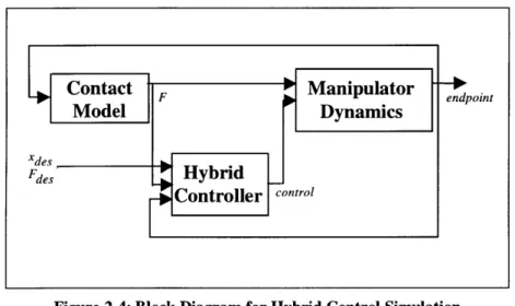
A general block diagram of these simulations is shown in Figure 2-4. The manipulator dynamics are that of a two-link planar robot arm including some viscous and breakaway joint friction. The manipulator dynamics block produces endpoint coordinates <x,y> as a function of input control torque and endpoint contact force, F. The contact model is that of a stiff circular surface which produces a normal contact force toward the center of the crucible. The contact forces and endpoint position are sensed and fed to the hybrid controller algorithm shown in Figure 2-2. This controller generates a control torque intended to effect tracking of the desired position and force trajectories,
Xdes and Fdes. The hybrid controller assumes that the position and force domain directions are known throughout the entire trial, and that switching of the projection matrices occurs as soon as contact is detected (when the contact force is greater than zero).
Contact F Manipulator endpoint
Model Dynamics
Xdes
Fdes Hybrid
Controller control
Figure 2-4: Block Diagram for Hybrid Control Simulation
In the simulated experiments, the end-effector starts at position <1,0> and moves under pure position control (P=I, F=O) with a speed of 0.33 units per second in the -y direction until contact is made with the crucible. Once contact is detected, the system
switches selection matrices so that there is position control in the x direction and force control in the y direction.
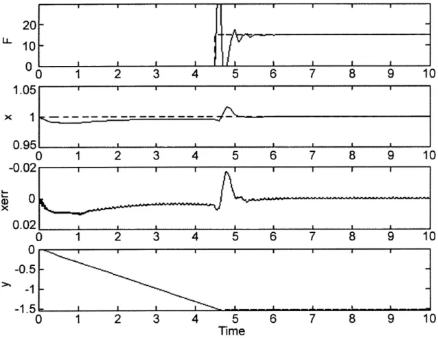
Figure 2-5 shows the results of an experiment in which the end-effector is held fixed after contact and the contact force is commanded to be regulated at 15 Newtons. Contact is detected at 4.5 seconds and results in a large initial force spike and oscillation. There is also a momentary positioning error. The contact force is then quickly regulated to the desired force of 15 Newtons.
-1.C 0. -0.( -0 -1 0-I [ I I
0
1
2
3
4
5
6
7
8
9
1
0 1 2 3 4 5 6 7 8 9 022k-
0-
--0 ) 2 .. ... ... ... ... .... ... ... ... ... ... .... ... ... ... ..., .... ... ... ....... .... ... .. ... .,.. ...,.. ... ..., ... ... ... ... ... ... . u 0-.5 -1 .5 = 1 2 j 4 5 D 7 8 IU1 0 1 2 3 4 5 6 7 8 9 10 Time
Figure 2-5: Simulation Results, Endpoint Held Fixed After Contact
Figure 2-6 shows the results of an experiment in which the end-effector is commanded to slide along the crucible surface in the x direction after contact. The desired position is a sinusoid of amplitude 0.02 units and period 6.28 seconds. Note that
Chapter 2: Hybrid Position/Force Control Algorithms 29
the amplitude is small enough that the y position of the trajectory is essentially constant. Again, the contact force is to be regulated at 15 Newtons. Contact is detected at 4.5 seconds, and again results in a large initial force spike and momentary positioning error. The contact force is then regulated relatively quickly to nearly 15 Newtons, although in this case there are small deviations of approximately 0.5 units in amplitude. There is a lag in the position tracking, which creates a periodic error of about 0.003 units in amplitude. 20 L. 10 0 1.02 x 1 0.98 C 0.02 -O S0 x 0.02 0 -0.5 -1 -1.5 C -2 4 8 10 12 14 16 18 2C 2 4 6 8 10 12 14 16 18 2C 2 4 6 8 10 12 14 16 18 2C -\' , ' . . ... . . . - . . .. . . . . . . . . . . . .t. . . . . 2 4 6 8 10 12 14 Time
Figure 2-6: Simulation Results, Sinusoidal Motion
16 18 20
2.3 Summary
The hybrid position/force control algorithm presented in this chapter is the kernel of the control system for the RACS laboratory demonstration system. The simulation of
Chapter 2: Hybrid Position/Force Control Algorithms 30
I
)
this simple algorithm shows acceptable results; the force errors are less than 5 percent, and therefore would not cause damage to the crucible while the contact point slides. It is hypothesized that these algorithms can be used to safely place nuggets in the crucible.
Chapter 3
Hybrid Position/Force Control Experiments
3.1 Experiments on a Puma 250 Manipulator
The Jacobian Transpose algorithm presented in Chapter 2 was implemented and tested on a Puma 250 articulated robot manipulator. These tests were performed to verify the algorithm's suitability for use with the RACS system.
3.1.1 Apparatus
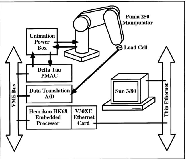
Figure 3-1 depicts the Puma 250 experimental setup, located at the MIT Field and Space Robotics Laboratory. This system was developed by past members of the lab, and is documented in (Idris, 1992). The control code software is written in C and compiled on a Sun 3/80 workstation. This code runs on a Heurikon HK68 embedded processor, which communicates to the Sun workstation via a piggy-backed V30XE extended ethernet card. The control code issues torque commands via VME Bus to the Programmable Multi-Axis Controller (PMAC). The PMAC can either accept torque commands from the Heurikon processor, or generate its own torque commands (the PMAC itself can implement PID position control). The PMAC then sends current signals to the Unimation power box, which powers the motors of the Puma 250 manipulator. Encoders in the joints of the manipulator send joint position information back through the power box to the PMAC. Force information from the load cell is passed to an A/D conversion board made by Data Translation, Inc. The A/D board and PMAC convey the
force and position information to the control code running on the Heurikon processor via the VME Bus. Experimental data is collected and saved to the hard drive on the Sun 3/80.
Figure 3-1: Experimental Apparatus for Puma 250
Figure 3-2 shows the structure of the Puma 250 manipulator. The Puma 250 is nominally a six degree-of-freedom vertically articulated robot arm, although for the following experiments the last three (wrist) joints are fixed. The load cell is mounted to the endpoint of the robot; this sensor can measure forces applied along the axis of the last link. The manipulator kinematics are described in Appendix A.
Figure 3-2: The Puma 250 Manipulator
3.1.2 Experimental Procedure - Roller and Nugget Tests
The experiments performed on the Puma 250 are divided into two categories: roller tests and nugget tests.
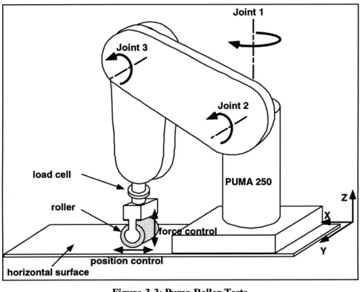
The roller test, illustrated in Figure 3-3, involves the regulation of contact force in the z direction while rolling along a wooden horizontal surface (the x-y plane). The end-effector for these experiments is a wooden cylindrical roller mounted onto the load cell. At the start of each trial, the roller is held several centimeters above the horizontal surface. Since there is no contact with the environment, every task-space direction lies in the position control domain (P=I), and there is no force control domain (F=0). The system is commanded to slowly move the roller vertically downward toward the table until contact is made. The system detects contact when the load cell measures a contact force above an empirically-determined threshold. Once contact is detected, the position control domain is restricted to the x and y directions, and the force control domain
expands to include the z direction. The roller is commanded to either be held fixed, or to roll back and forth along the surface while maintaining a desired vertical force.
Figure 3-3: Puma Roller Tests
The nugget test, depicted in Figure 3-4, is similar to the roller test but simulates the nature of the wall-building process. In this case the end-effector firmly grips a silicon nugget and the contact surface is a glass wall. The nugget tests involve the regulation of contact force in the x direction while sliding along a vertical surface (the y-z plane). At the start of each trial, the nugget is held several centimeters in front of the vertical glass surface. The system is commanded to slowly move the nugget toward the wall until contact is made. Again, the nugget is commanded to either be held fixed, or to slide back and forth along the surface while maintaining a desired force.
Figure 3-4: Puma Nugget Tests
3.1.3 Experimental Results
Figure 3-5 shows the typical results of a roller experiment in which the end-effector is held fixed. A desired contact force of 5 Newtons is commanded once contact is made. The endpoint begins approximately five centimeters above the surface and moves downward. Contact is detected at approximately 1.5 seconds. It can be seen that the contact force quickly converges to the desired force.
0 2 4 6 8 10
20
195
0
2
4
6
8
10
- 2 E E .0-x -2 0 Iu E 5 N 0 2 4 6 8 I I I I 1 0 2 4 6 8 10 Time (s)Figure 3-5: Puma Roller Test Results, Roller Held Fixed
Figure 3-6 shows the typical results to a roller experiment in which the end-effector is commanded to roll along the surface once contact is made. The desired position trajectory is a one-dimensional sinusoid with a 4-cm amplitude and a 0.25-Hz frequency. The endpoint again begins approximately five centimeters above the surface and moves downward. Contact is detected at approximately 1.5 seconds. The desired contact force is 5 Newtons. The system maintains contact with the surface; the measured force is always nonzero after initial contact. The position controller shows rather poor performance; there is significant lag, especially when the roller direction is commanded to change. The plateaus in the graph indicate that the roller sticks at the extrema of the path. Thus there is a position error of several millimeters. In this trial, the force
Chapter 3: Hybrid Position/Force Control Experiments 37
regulation is moderately successful; the average (zero-frequency) force is maintained at 5 Newtons. However, there is also a disturbance which causes a deviation of nearly 5 Newtons from the desired force.
z 10 -LLI I I I
20
0 2 4 6 8 10 25 15 0 2 4 6 8 10 x -2 -50 2 4 6 8 10contact
N0
1.5 2
4
6
8
10
Time (s)Figure 3-6: Puma Roller Test Results, Roller in Motion
Figure 3-7 shows the typical results of a nugget experiment in which the end-effector is held fixed once contact is made. The endpoint begins approximately three centimeters in front of the surface and moves forward. Contact is made and detected at approximately 0.5 seconds. The desired contact force is again 5 Newtons. It can be seen that, as in the roller case, the contact force converges on the desired force after an initial force spike.
LL 230 0.5 2 E Q 22.5 4 6 8 N 1 0 0 0.5 2 4 6 8 10 50 45 I 0 0.5 2 4 6 8 10 Time (s)
Figure 3-7: Puma Nugget Test Results, Nugget Held Fixed
Figure 3-8 shows the typical results of a nugget experiment in which the end-effector is commanded to slide the nugget along the glass surface with a desired contact force of 5 Newtons once contact is made. The desired position trajectory is a one-dimensional sinusoid with a 4-cm amplitude and a slow, 0.1-Hz frequency. The endpoint again begins approximately three centimeters from the wall and moves toward it.
Contact is detected at approximately 1 second. The behavior is somewhat degraded from that of the roller test. The system does maintain contact with the surface, although the contact force does momentarily drop to nearly zero about 7 seconds into the trial. Again, the position controller shows rather poor performance; there is significant lag, and plateaus in the graph indicate sticking. Thus there is position error of up to two centimeters. In this case, the force regulation is somewhat successful; the average force is indeed maintained at 5 Newtons. However, there is also an occasional disturbance
force which causes a deviation anywhere from +7 Newtons to -5 Newtons. This negative deviation is nearly enough to cause contact to be lost.
10
0
5
10
15
30
-20
~--
_ i
N 10 0 5 10 15 N20 0 5 10 1545
0
5
10
15
Time (s)
Figure 3-8: Puma Nugget Test Results, Nugget in Motion
3.1.4 Summary of Puma Experimental Results
This testing demonstrates that the system can accurately maintain a desired force while the end-effector is held fixed. Performance is degraded when position control is not merely used as a regulator. Additional experiments were performed to isolate the cause of this degradation.
Experiments were performed in which the surfaces were more compliant and damped; however, the force spikes were still present. It was observed that in all experiments the manipulator would stick and slip during pure position motions, and that
the actual velocity of the end-effector would briefly have a significant component in a direction other than that desired.
These results indicate that the performance degradation is due largely to the presence of high amounts of backlash and nonlinear joint friction in the Puma 250, which
causes excessive coupling in the motion of the endpoint. Thus the manipulator tends to exert forces against the surface while it moves along the surface. It is expected that the AdeptOne manipulator in the RACS laboratory demonstration system exhibits much less friction and backlash.
3.2 Experiments on the AdeptOne Manipulator
The Jacobian Inverse hybrid position/force control algorithm presented in Chapter 2 was also implemented and tested on the AdeptOne manipulator for the laboratory demonstration system. These experiments were performed to further verify the suitability of hybrid position/force control for the RACS wall and crown building modes.
3.2.1 Apparatus
Figure 3-9 depicts the AdeptOne system apparatus. Torque commands are generated by an algorithm running on the control computer. These are sent to the joint controller cards in the controller unit. These cards convert the torque commands into current commands, which are specifically computed to compensate for the AdeptOne motor nonlinearities (Goldenberg et al., 1994). These command signals are fed to the power amplifiers, which in turn provide current to the robot's motors. Encoder signals reflecting joint positions are sent back to the joint controller cards, which send this information back to the control computer. Measurements from the wrist force/torque sensor are also supplied to the control computer.
' AdeptOne Manipulator Figure 3-9: Experimental Apparatus for the AdeptOne System
Figure 3-10 shows the structure of the AdeptOne manipulator. It is a four degree-of-freedom SCARA robot. The three rotational joints (1, 2, and 4) rotate their associated links in the x-y plane, and the prismatic joint (joint 3) translates linearly in the z direction. See Appendix A for the manipulator kinematics.
3.2.2 Experimental Procedure - Roller and Nugget Tests
As with the Puma 250, roller experiments were performed on the AdeptOne system. The end-effector for these experiments is a Delrin cylindrical roller mounted onto the six-axis wrist force/torque sensor. The horizontal surface is a thick aluminum plate. Refer to section 3.1.2 above for a detailed description of the experimental procedure.
Joint 2
Figure 3-10: The AdeptOne Manipulator
Nugget experiments were also performed against a vertical wall, as described in section 3.1.2 above. For these experiments, a stiff metal surface replaced the glass wall. Since the AdeptOne manipulator is much more powerful than the Puma 250, it poses a greater risk of damage to the environment. The metal surface provides valid information about the important behavior of the control algorithm, without constant risk of breaking the glass, with its associated hazards and experimental delays.
3.2.3 Experimental Results
Figure 3-11 shows the typical results of a roller experiment in which the end-effector is held fixed after contact. The endpoint begins approximately seven centimeters above the surface and moves downward. Contact is detected at approximately 6 seconds. The desired contact force is 20 Newtons. It can be seen that after an initial contact force spike, the contact force quickly converges on the desired force.
20
-61
LL0
650
5 6
10
15
20
65.5
64.50
5 6
10
15
20
E 01 e __ 0.05 -x u000 5 6 10 15 2085
NU80 75 0 5 6 10 15 20 Time (s)Figure 3-11: AdeptOne Roller Test Results, Roller Held Fixed
Figure 3-12 shows the typical results of a roller experiment in which the end-effector is commanded to roll along the surface once contact is established. The desired position trajectory is a one-dimensional sinusoid with a 3-cm amplitude and a 0.25-Hz frequency. The endpoint begins approximately one centimeter above the surface and moves downward. Contact is detected at approximately 1.8 seconds. The desired contact force is 20 Newtons.
As with the Puma 250, the system maintains contact with the surface; the contact force is always nonzero after initial contact. The position controller shows improved performance over the Puma 250, but there is still significant lag when the roller direction is commanded to change. The plateaus persist, and there is a maximum position error of
about 5 millimeters. In this case, the force regulation is moderately successful; the average (zero-frequency) force is maintained at 20 Newtons. However, there is also a disturbance which causes a momentary deviation of up to 15 Newtons from the desired force.
40
20
-0
1.8
5
10
15
50
45-40
0
1.8
5
10
15
10 X -10 0 1.8 5 10 1577.5
- 7776.5
0
1.8
5
10
15
Time (s)
Figure 3-12: AdeptOne Roller Test Results, Roller in Motion
The nugget tests showed similar results. Figure 3-13 depicts the result of a test in which the nugget is held fixed against the vertical wall. Once contact is detected, the force profile oscillates for several seconds and settles on the chosen value of 5 Newtons, which was experimentally determined not to cause scratching of the glass. Deviations of approximately 0.5 Newtons are purely the result of sensor noise. When the sensor is stationary and not in contact with any object, tests show that the force signal tends to deviate from zero by up to 0.5 Newtons.
The z-positioning error was very small in this example (less than 0.02 millimeters) because the system was acting as a regulator in this direction, and the dynamics of the prismatic joint (z-direction) are decoupled from that of the rest of the manipulator system.
710
-LL 5-01
0
5
10
15
76.5
o 76 75.50
5
10
15
0.04
-0.02 N 0-57.5
57
,
0
5
10
15
Time (s)
Figure 3-13: AdeptOne Nugget Results, Nugget Held Fixed
Figure 3-14 shows the results of a trial in which the nugget is commanded to slide in the vertical (z) direction while in contact with the wall. The desired contact force is 5 Newtons. The desired position trajectory is a sinusoid of amplitude 1 cm and period 10 seconds. Contact is detected at approximately one second. The force controller is somewhat able to maintain the desired force, with deviations ranging from +1 to -2.5 Newtons. The position controller also shows moderate performance, maintaining the
vertical position error to within -t2 mm. This performance is certainly improved over that of the Puma 250. 5-0 1 5 10 15
)76
.
N75
0
1
5
10
15
I-2 0 1 5 10 15 Time (s)Figure 3-14: Adept Nugget Test results, Nugget in Motion
3.2.4 Summary of AdeptOne Experiments
This testing demonstrates that, like the Puma 250, the AdeptOne system can maintain a desired force while the end-effector is held fixed. Performance is still degraded when position control is not merely used as a regulator. Experiments were performed to determine the cause of this degradation.
Further roller tests were conducted in which the steel plate was covered with a thin layer of rubber to prevent force spikes due to the nature of contact. The results were qualitatively similar to those of Figure 3-12; this suggests that the primary cause of disturbance is not contact surface roughness.
The experimental results suggest that several factors influence this degradation: dynamic coupling in the control algorithm, force sensor cross-talk, and joint friction.
The deviations in the force profile seen in the nugget experiments may be caused by the approximations made in the control algorithm, see section 2.1.2. Under pure position motions of the manipulator, the actual velocity was seen to deviate in direction from the desired. Although the position controller and the force controller are supposed to act in orthogonal directions, there is a certain degree of dynamic coupling. Note that this was not seen in the roller experiments, where the force domain consisted only of the vertical z direction. The motion of the prismatic joint is decoupled from the other degrees of freedom, as can be intuited from its Jacobian matrix (see Appendix A).
It was also observed that there was cross-talk in the wrist force-torque sensor. Experiments showed that forces perpendicular to the target direction would register significant readings. The system cannot distinguish between actual forces in the contact direction and these false readings, and thus it attempts to control these deviations. This effect becomes significant when the manipulator slides along the surface, generating significant frictional contact forces.
Finally, although the AdeptOne manipulator exhibits generally lower joint friction than the Puma 250, it is apparent that the effect of joint friction is still significant. This leads to the joint positioning plateaus, as well as the same sort of coupling between the force and position domains seen in the Puma 250.
It was observed during these tests that the angular position integrator in the wrist joint (joint 4) would sometimes "fight" with the force integrator, as depicted in Figure 3-15. The force performance against glass would suffer while the orientation of the wrist
would be corrected. This problem arose because of the nature of the nugget contact with the wall. In order to fix this problem, the position integrator for the wrist was deactivated during the wall contact. Therefore the wrist joint is under joint PD control during contact. Perfect steady-state positioning of the wrist was sacrificed in favor of more robust force performance.
Angular Force control control Contact point
End-effector
NuggetFigure 3-15: Contention Between Force and Position Integrators
3.3 Summary and Discussion of Experimental Results
The experimental results demonstrated above show that the implemented hybrid position/force control algorithms perform very well when the position controller is merely a regulator, and show some degree of success with simultaneous motion and force profiles. However, the performance degradation is significant. It is not clear that the disturbance force oscillations will always remain in a safe range, although the manipulators did not significantly exceed this range during the course of the experiments.
Additional experiments suggest that the force control performance degradation is caused by a variety of phenomena; this indicates that the force domain of the hybrid control algorithms is very sensitive to disturbances of any kind. Unmodelled dynamics,
joint friction and transverse forces introduce time-varying disturbance forces into the control loop. The position domain is generally robust to these forces; the manipulator dynamics filters disturbances by integrating them twice. The force domain is not robust to these disturbances, however. They directly affect the endpoint force, and there is no filter to attenuate their effects. To obtain better performance with a hybrid controller, it may therefore be necessary to eliminate these disturbances. Additionally, the elimination of these disturbances would further verify their roles as the sources of the questionable behavior.
Degradation due to unmodelled dynamics could be removed by the implementation of a more complex control algorithm. Such a control algorithm would take into account the full dynamic model from (2 - 1). This requires the knowledge of inertial parameters. Cross-talk in the force sensor could be reduced by determining an appropriate decoupling matrix.
It may also be necessary to eliminate the effects of joint friction. Significant stick-slip behavior was seen in even the low-friction AdeptOne. A friction compensation scheme such as BaST control (Morel and Dubowsky, 1996) could remove the effects of friction at the low speeds required by the RACS control system.
The implemented hybrid position/force control algorithms are sufficient for pure regulation of position and force. Trajectory tracking performance is less reliable, but may be acceptable for controlling contact with the crucible. Further research is recommended to improve the behavior before the algorithms are incorporated into a RACS system.