Design Analysis of the Four-bar Jaipur-Stanford Prosthetic Knee for Developing Countries
by
Casandra N. Ceri
Submitted to the
Department of Mechanical Engineering
in Partial Fulfillment of the Requirement for the Degree of
Bachelor of Science in Mechanical Engineering
at the
Massachusetts Institute of Technology
June 2013
ARCHtNES
MASSACHUSETTS INSTTfTE OF TECHNOLOGYJUL 3
1
2013
LIBRARIES
© 2013 Massachusetts Institute of Technology. All rights reserved.
Signature of Author:
UDepartnknt of Mechanical Engineering May 14, 2013
Certified by:
Amos G Winter Noyce Career Deve opment Assistant Professor Thesis Supervisor
Accepted by:
Anette Hosoi Professor of Mechanical Engineering Undergraduate Officer
Design Analysis of the Four-bar Jaipur-Stanford Prosthetic Knee for Developing Countries
by
Casandra N. Ceri
Submitted to the Department of Mechanical Engineering on May 14, 2013 in Partial Fulfillment of the
Requirements for the Degree of
Bachelor of Science in Mechanical Engineering
ABSTRACT
Amputees in developing countries face a challenging prospect. Without an adequate prosthesis, they face a lifetime of limited mobility and dependence. Unfortunately, as millions fall below the poverty line and as such do not have access to proper medical and prosthesis care, many must resign themselves to such a lifestyle. Bhagwan Mahaveer Viklang Sahayata Samiti (BMVSS) is attempting to change this. BMVSS is the world's leading prosthetics and mobility provider, serving over 20,000 new individuals per year - all free of charge - in 27 countries. Through a partnership with a Stanford design course, the Jaipur-Stanford Knee, a novel prosthetic knee incorporating a four-bar design, was born. This knee design has become widely popular amongst amputees and was named one of the top 50 best inventions in 2009 by Time Magazine. However, despite the popularity and widespread media coverage of the knee's development, there currently exists no available technical literature on the design. This research provides a kinematic model of this knee to compare to the dynamics of a natural gait along with a materials analysis to offer insight into design and manufacture improvements in future design iterations and concepts.
Thesis Supervisor: Amos G. Winter
Tile: Noyce Career Development Assistant Professor, Director of Global Engineering and Research (GEAR) Lab
ACKNOWLEDGMENTS
The author would like to thank first and foremost her advisor, Professor Amos G. Winter, for providing her this wonderful opportunity to work with the Global Engineering and Research Laboratory and for offering her his continual support and advice throughout the duration this project. She would also like to express her gratitude to Mr. Yashraj Narang, without whose guidance and consultation, this research would not have been possible.
Lastly, a thank you to the Bhagwan Mahaveer Viklang Sahayata Samiti organization is owed for their continual support and partnership with the GEAR Laboratory to better the lives of those amputees facing the struggles and life-altering aspects of limited mobility in developing countries through the provision of free, low-cost prostheses.
Table of Contents
ACKN OW LEDGM ENTS ... 3
Table of Figures ... 5
1. Introduction ... 6
1. 1 Current Knee Prosthetics ... 6
1. 1. 1 Developed Country M odels ... 6
1. 1. 2 Developing Country M odels ... 8
1.2 Bhagwan M ahaveer Viklang Sahayata Sam iti ... 9
2. M aterials Analysis ... 11
2.1 Developed W orld ... 11
2.2 Developing W orld ... 11
2 .3 R e su lts ... 12
2.4 Conclusion ... 12
3. Prosthetic Knee Dynam ics ... 12
3.1 General Theory ... 12
3. LI Four-bar M echanism Governing Kinematics ... 12
3.1.2 The Gait Cycle ... 17
3.1.3 Prosthetic Knee Stability ... 19
3.2 Jaipur Stanford Knee Analysis Results ... 21
4. Conclusions ... 26
APPENDIX A ... 27
APPENDIX B ... 28
Table of Figures
Figure 1: Four-bar mechanism linkage classification... 13
Figure 2: Jaipur Knee four-bar mechanism design. ... 14
Figure 3: Extension position (top) and flexed position (bottom) of the Jaipur-Stanford four b ar k n ee . ... 15
Figure 4: Demonstration of the method of finding a four-bar's center of rotation... 17
Figure 5: First three stance phases of the natural gait cycle. ... 18
Figure 6: The beginning and end of the three stance phases. ... 19
Figure 7: Center of Rotation trajectories for 8 of the most common knee joints available in developed countries presently... 20
Figure 8: Solid model of the Jaipur-Stanford knee in the fully extended configuration ... 22
Figure 9: The trajectory of the CoR through the Jaipur-Stanford knee through the joint's entire range of m otion ... 23
Figure 10: The CoR trajectory of the Jaipur-Stanford knee in the first phase of a natural g ait cy cle ... 2 4 Figure 11: The CoR trajectory of the Jaipur-Stanford knee in the final phase of a natural g ait cy cle ... 2 5 Figure 12: Terminal Swing and Initial Contact phase positions ... 26
1. Introduction
1.1 Current Knee Prosthetics
Available knee joint designs in the developing world differ greatly from those in the developed world. As of publication date, current options for above knee amputees in the developed countries range from the most basic option of the single-axis knee to joints with onboard microprocessor phase control - the most advanced available on the market today. Individuals are prescribed specific knee prostheses based on age and expected level of activity and stability; elderly amputees will often employ more stable designs incorporating mechanical swing control while younger, more active amputees benefit greatly from the cadence and terrain variance achievable by designs utilizing hydraulic and pneumatic phase controls (J. S.-M. Andrysek; Romo)
1.1.1 Developed Country Models
In the developed world, prosthetic knees can be divided into two categories based on their functional attributes: purely mechanical designs and microprocessor-controlled designs (Michael). The oldest moving design still in use in the developed world is the single-axis knee. The single axis knee is comprised of a single axis hinge that allows the joint to flex within one plane of motion about a fixed center of rotation (Michael; J. Andrysek). In the developed world, the single axis knee is most commonly paired with a damping braking system for swing phase control with the most basic incorporating a simple friction cell to aid in the terminal swing phase of the gait cycle when the leg is fully extended before heel strike (J. Andrysek; Romo). A spring-loaded or elastic module within the joint can be utilized to assist in this extension phase. Using this most basic setup tends to offer poor variability in a user's walking speed (Romo) but offers the least cost and lowest required maintenance option (Michael).
To overcome the single cadence limitation of the basic friction-cell single-axis knee, several designs have incorporated other means of swing and stance phase controls. A weight-activated friction brake attempted to solve the problem through a stance phase only brake that activated at the onset of load bearing on the affected limb and deactivated at the point of weight shift to the
unaffected limb. This design though has yet to see promising results, having suffered from high instability problems and knee flexion interference at high speeds, effectively limiting the user's cadence band to a very narrow margin (J. Andrysek). Fluid-controlled systems have attempted to correct the problems faced by these constant friction designs. These systems offer variable swing control which enables the user to walk at varying cadences. This is due to the dampening effect the controls exert on the swing of the shin. Without the dampening effect, the user must wait for the prosthesis to swing through the swing phases due to the added momentum caused by the quicker walking pace (Michael).
Pneumatic control schemes have been able to achieve this goal while only adding a few ounces to the overall weight of the joint and just 15% additional cost to the prosthesis. However, while they can achieve a wider range of cadences and are not adversely affected by environmental changes in temperature, the pneumatic controls exhibit a still narrower band of possible cadences than models incorporating hydraulic schemes. Hydraulic phase control offer the most stable and reliable option for users of varying walking speed and terrain. The mechanisms offer the user variable cadences with flow restriction and/or flow regime characteristics to provide high damping through the swing phase. The benefits of a hydraulic module are demonstrated by the popularity and longevity of current designs. One of the oldest knee models in use is the S-N-S hydraulic knee -developed over 50 years ago. The design offers premiere stance and swing phase control, often allowing users to master normal step-over-step gait when climbing and descending stairs as opposed to a step-by-step gait (when the climber places two feet on a stair before stepping up to the next) (Michael).
For those desiring higher stability than the single-axis knee but are capable of more energy exertion to achieve it, another purely mechanical option is the polycentric knee utilizing multiple bar mechanisms. These designs are often optimized for a specific stance or swing phase based on the predicted level or manner of activity (Michael; J. S.-M. Andrysek; Romo). They operate on linkage design to control the location of the instantaneous center of rotation to determine stability. They offer greater toe clearance at mid-swing than single-axis knees which results in a higher confidence level by the user in the prostheses (Michael). Higher confidence levels in turn result in less stumbling and over compensation (more energy exertion) by the individual. Like
the single axis knee, these designs can be combined with a constant friction module for mono-cadence users or a fluid-controlled module for more active, variable mono-cadence users.
Microprocessor controlled designs offer the best gait symmetry of the available knee design options. The most popular models offer variable pneumatic or hydraulic swing control by feedback from onboard sensors that detect the current configuration of the socket-knee-pylon assembly. The feedback control is often optimized during prosthesis fitting and dynamic alignment. Feedback signals are often sampled numerous times per second to apply the microprocessor's control algorithm to offer adjustment to resistances up to 60 times during a single step (Michael). These models offer high levels of confidence and thus a better, more natural gait and lead to less energy expenditure when trying to correctly time the swing phase.
1.1.2 Developing Country Models
In the developing world, due to economic conditions, most knee models tend to use purely mechanical means. Most individuals in developing countries have very limited access to medical care. As a consequence, these designs also must emphasize longevity and low failure rates in addition to the basic design. The most common model is the single axis knee with no swing phase control. This joint design suits the little to no maintenance lifespan seen by the prosthesis and offers the lowest cost of manufacture and material supply (J. S.-M. Andrysek; Michael). As mentioned before this model exhibits stability problems caused by the location of the joint's center of rotation and offers no variance in walking speed (Michael). Many individuals consequently will have a manually locking single axis knee allowing them to switch to a non-articulating joint in favor of a peg-leg function for more stability over rugged terrain or crowded spaces (J. Andrysek; J. S.-M. Andrysek; Michael). One of the most successful knees, the ICRC Knee, features such a manually locking function. This knee also exhibits a low failure rate of just
32% after 15 months. However, this knee offers no more than the manual locking feature, offering no in-gait swing or stance control. ATLAS attempted to address the absence of control through their weight-activated friction knee, in addition to Georgia State with the Friction Knee and the University of Melbourne with the Wedgelock Knee. All three models showcased unreliable function and high rates of structural failure; the ATLAS knee experienced an 83% failure rate after just 7-10 months. The reliability problems experienced in the attempted designs
were largely due to the high rate of wear on the braking mechanisms and changes in the coefficient of frictions due to environmental variables such as humidity and moisture, coupled with the users' lack of access to regular prosthesis maintenance (J. Andrysek).
The four-bar mechanism is currently experiencing a surge in popularity in the developing world as better and cheaper design solutions are developed. The four-bar knee benefits from the stability of a polycentric design while also requiring relatively inexpensive materials and manufacturing methods. Most models available in the developing world are made from low-costing polymers capable of simple machining using basic machinery such as band saws, drill presses, and power sanders. Current improvements aim at making the joint profile more streamlined and aesthetically pleasing, provide better and more reliable stability over rugged terrain, and offer wider ranges of motion to accommodate common, often daily postures found in developing countries that are not so in developed, such as sitting cross-legged and squatting.
1.2 Bhagwan Mahaveer Viklang Sahayata Samiti
Bhagwan Mahaveer Viklang Sahayata Samiti (also known as Jaipur Foot) is the largest prosthetics provider in India, servicing some of the over 6 million amputees in the country. On average, they add an additional 25,000 amputees per year to their list of those helped. They offer 7 service centers in India, host numerous mobile campus each year to reach isolated, rural amputees, and also offer services in 19 other countries including Honduras, Malawi, Indonesia, Panama, and Afghanistan. Additionally, they are a profit, government, and non-religious organization, offering all of these services free-of-charge to amputees (Macke, Misra and Sharma). As such, low-cost prostheses are a major concern for the organization in regards to maximizing the number of individuals it can help. The company aims to minimize manufacturing cost by simplifying the process and employing the most inexpensive materials with the best engineering properties for the specified application.
Most amputees seen by Jaipur Foot fall below the poverty line and as such have little to no access to medical care and prosthetic services. Of the over 6 million amputees, approximately 1.7 million have experienced above-the-knee amputations (Stanford GSB). Most of the amputations are the result of transportation-related accidents, polio and other diseases, and other
situations. In many former-conflict zones, these amputations are the result of left over hidden mines. For perspective, it is estimated that roughly 10 million hidden landmines remain in Afghanistan; Cambodia is estimated to have as many landmines buried beneath the countryside as citizens in the country. As a consequence of situations like this, many amputees from former conflict zones tend to be women and children injured while walking in fields or down roadsides (Macke, Misra and Sharma).
At the time of publication, Jaipur Foot offers three knee designs: the exoskeleton knee, the single-axis knee, the Jaipur-Stanford Knee. The exoskeleton knee is a fixed knee offering no joint rotation. It acts as a peg-leg joint; individual's gait with the exoskeleton knee is very rigid and inefficient requiring the user to have an unnatural gait requiring high hip torque and high impact stresses on the unaffected limb to step forward. The single axis knee is offered with and without a manually locking mechanism for when traversing over uneven terrains (JaipurFoot). The design requires axis alignment to be positioned behind the weight bearing line along with voluntary control of the residuum hip muscles in order to resist the knee's flexion during the loading phases (JaipurFoot). The design has been shown to be unfavorable for rough or uneven terrain - a daily obstacle in the developing world where paved roads and walkways are not necessarily frequent (J. Andrysek). As a result, many users of the single axis knee provided by Jaipur Foot will use the knee with the manual lock engaged consistently.
The Jaipur-Stanford Knee is Jaipur Foot's newest offering for its users and will be the subject of focus for this publication. At the time of this writing, the knee is a four-bar mechanism knee made of oil-impregnated nylon. The design was developed by a design team from Stanford University in conjunction with Jaipur Foot as capstone project through an offered design development course. The goals of the project were to design a knee that would cost no more than
$35.00 to produce and would withstand the environmental challenges of India (dust, sun
exposure, rugged terrain, humidity levels) with little to no maintenance (Stanford GSB; BMVSS). The design entails a non-Grashof four bar that partially limits the total allowable rotation of the joint to 1500 from the 0' axis designation at full extension. The joint enables relatively natural gait movement but still experiences abrasion wear problems and stability inconsistencies.
2. Materials Analysis
The goal of the Jaipur-Stanford Knee should be to equal or surpass the lifetime of the organization's popular Jaipur Foot prosthetic. Failure of the knee before the foot will guarantee loss of function of the entire assembly. The foot prosthetic design exhibits an average survival rate of 70% after 16 months in use and an average lifespan of three to four years (J. Andrysek; BMVSS). The material selection should also address the minimization of rot from excessive moisture, fatigue wear, and deterioration due to direct sunlight exposure. In addition to the mechanical properties of the materials selected, the selected material stock should be of minimal cost to the organization in hopes of falling well below the set total cost of the joint.
2.1 Developed World
Prosthetic knees in the developed world tend to choose materials based on mechanical properties regardless of cost. Most materials include high strength metals and metal alloys with low density and high corrosion and fatigue rating properties. The most common of such materials include stainless steel, aluminum, and titanium. Bearing or contact surfaces are often seen comprised of copolymers or other thermoplastics due to their low friction properties and self lubricating natures. A few models exist in the developed market that offer joints made almost exclusively of thermoplastics more characteristic of the developing markets. These knees are often advertised as "rugged" joints intended for outdoor activity and tend to follow a 4- or 6-bar mechanism design. As a result of material choices and manufacturing processes, knee joints commonly found in developed countries tend to run hundreds of US dollars in price.
2.2 Developing World
Because many amputees in the developing world live below the poverty line and have little to no access to routine medical care, material choices are dependent heavily upon local material costs and wear life. Most designs employ thermoplastics as the main material component. Thermoplastics offer relatively low bulk pricing, ease of machining, low friction, and low abrasion and wear properties with respect to density values. Their intrinsic properties also allow the recycling of left over material for reuse in joints and overall reduction in manufacturing cost. The most common of materials used include several different types of Nylon, polypropylene,
polyethylene (HDPE), and polyacetal resin (Delrin). Occasionally, high strength metals are used in the construction of the cylindrical pylon components because of the little machining required (and thus reduced cost) for each component coupled with the optimal mechanical properties.
2.3 Results
Commonly used materials in prosthetic knee joint found in developed and developing countries were researched and compared using characteristics weighted upon importance to the joint design. The weighted comparison can be found in the Pugh chart (Table 2) on page 26. Materials compared were Nylon 6, Nylon 6-6, oil-filled Nylon, isotactic polypropylene, acrylonitrile butadiene styrene (ABS), polyacetyl resin (Delrin), stainless steel, aluminum (60-series), titanium, polyethylene (high density), and polyvinyl chlorine (PVC).
2.4 Conclusion
As the Pugh chart shows, the optimal material selection for a prosthetic knee in a developing country will consist of thermoplastics, as is presently common. The highest-rated materials are Nylon 6 or high-density polyethylene (HDPE). Both materials exhibit the best yield strength properties. Although HDPE shows lower wear properties, its low cost benefits the material's choice for low cost prosthetics. Its common use in present-day surgical joint replacement lends to its reputation of reliability. HDPE exhibits excellent corrosion resistance and has favorable failure modes as it tends to rip or rear rather than drastic failure though shattering. It is also easily recycled contributing to even lower overall manufacturing costs. Nylon 6 exhibits favorable strength and excellent wear properties. Nylon 6 is highly abrasion resistant making it an ideal material for use in an open joint in environments heavy in dust and dirt as found in India and other developing countries.
3. Prosthetic Knee Dynamics
3.1 General Theory
3.].] Four-bar Mechanism Governing Kinematics
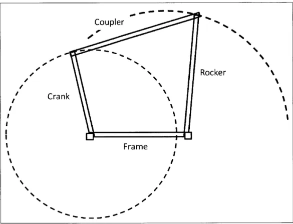
The four-bar mechanism outputs a specific path trajectory with a rotational input on one linkage in the mechanism. It is comprised of four types of linkages: the frame, the fixed link; the
coupler, the link not connected to the frame linkage; a crank linkage, the link that rotates a full 360'; and a rocker linkage, the link that rotates less than 360' (Zhang, Finger and Behrens).
Figure 1: Four-bar mechanism linkage classification.
A four-bar may be comprised of one or two cranks or rockers but will always contain a frame and a coupler linkage. The combination of the crank and rocker will determine the mechanism's classification. In a Grashof four-bar linkage, the lengths of the linkages follow the
following relation:
Lmax + Lmin ; La + Lb, (1)
where Lmax is the longest link, Lmin is the shortest link, and La and Lb are the remaining two links. If the mechanism does not follow the relation found in equation (1), the mechanism is said
Coupler
Rocker\
Cra nkx
to be a "non-Grashof" mechanism. In such a mechanism, the two side links are limited in the rotational range of motion due to the geometries of the links combined with the frame and the coupler. As such, to model the behavior of such a mechanism as a mathematical program, angle relations must be determined and the angle limitations of one link (the input or control link) must be prescribed.
Lin
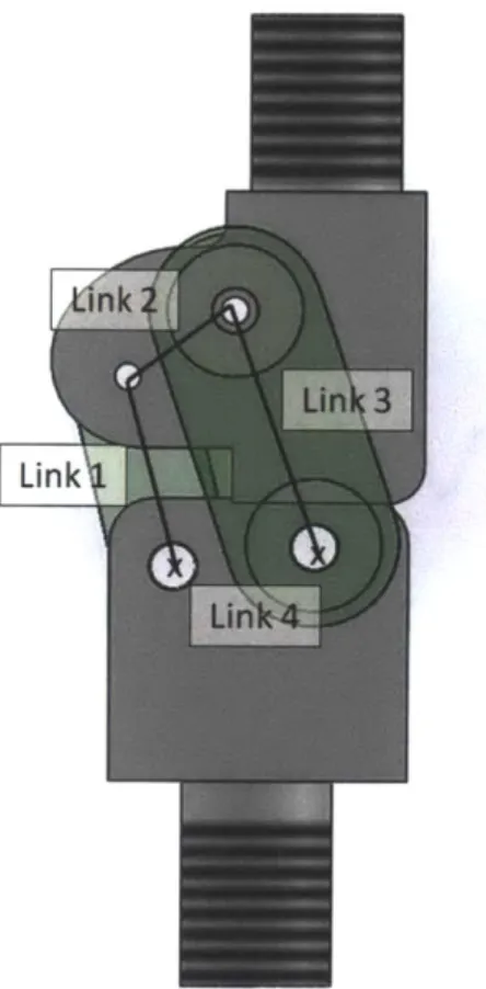
Figure 2: Jaipur Knee four-bar mechanism design.
The Jaipur-Knee 4-bar mechanism is a non-Grashof linkage (see Figure 2). As such, when modeling the linkages in the mathematical model, multiple geometrical relations were required to analyze the kinematic of the entire system. For the kinematics analysis in this publication,
Link 3 (see Figure 2) was used as the input link (in the actual prosthesis the socket component extruding at a fixed angle with respect to the coupler from the point B (see Figure 3) serves as the input link).
_ _B
_ _
__--
-2 q6s
A'
1A
--- - -.01, L3 LsFigure 3: Extension position (top) and flexed position (bottom) of the Jaipur-Stanford four bar knee. The driving angle is shown
as 04, the angle between Link 3 and the Horizontal axis. Not drawn to scale.
As one can see from Figure 3, six total angles and two additional distance relations were required to completely define the response of the mechanism to specific input angles at the location of Link 3's connection to the frame. The values of the x- and y-coordinates of point B were assumed known from the input angle of 64 and the length of Link 3. As such,
67 = cost (L
where
BX = cos(6 4) and By = sin(64). (3)
Combined, the relations found in equations (3) form
D= B2+ B 2 (4)
where D is the diagonal from the left most frame fixture to point B of the mechanism. Furthermore, applying the law of cosines to and summing the two sub angles of 61, we reach
61 = Cos-1 (D2 + L 2 -L 2 (5)
Continuing, to define the coupler link, we define 62 as
02 = IF + 66 - 67, where 66 = COS 1 (L + L -d2L) (6) (7)
Finally, to find the final location of the end of the coupler link and Link 1 and to complete the definition of 66 and consequently 62, we observe that
(8)
where, using the definition for 61 as described in equation ( 5 ), we assume that
AX = L1 cos(0 1) and A, = L1 sin(61) . (9)
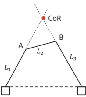
The coupler link of a four bar mechanism exhibits multiple instantaneous rotations of center depending upon the configuration of the four linkages. The center of rotation (CoR) is found by
+ Li -2 2D2L1 -cos_1 D2
extending the input and output links to the point of their intersection (as shown in Figure 4). This point of intersection will define the axis about which the links are rotating (Romo). This relation will prove critical in the stability of a four-bar prosthetic knee.
CoR
J/
B
A J
L2 L LaFigure 4: Demonstration of the method of finding a four-bar's center of rotation.
3.1.2 The Gait Cycle
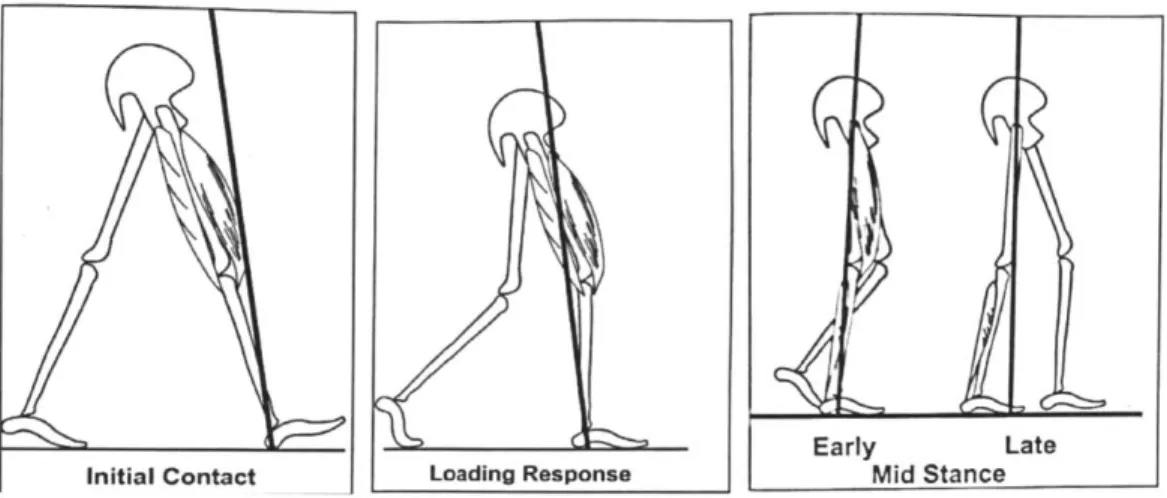
The natural gait cycle is divided into eight phases (Burnfield, Phases of Gait). The stance and swing phases take up approximately 60% and 40% of the cycle, respectively (Romo). The phases of concern for a non-swing phase-controlled prosthetic such as the single-axis knee and the polycentric knees found in developing countries consist of the stance phases. During the initial contact through to the beginning of terminal stance phases (Figure 5), the knee flexes to cushion impact forces and prepare for the shifting of weight seen at the end of terminal stance and into the pre-swing phase (Burnfield, Phases of Gait).
Initial Contact Loading Response Early Mid StanceLate
Figure 5: First three stance phases of the natural gait cycle: initial contact, loading response, and mid-stance. The black lines extending through the femoral head indicate the loading line. (source: Burnfield, Phases of Gait)
Throughout this portion of the gait cycle, the knee naturally tends to exhibit a maximum of 18' flexion (where the 0' axis is defined as the leg in full extension) to allow the rolling motion of the foot and toe clearance (Romo). This causes the location of the center of rotation to move forward and the ground forces backward of the knee aiding in the flexion (or controlled buckling) of the limb. In the absence of stabilizing quadriceps and knee muscles, the leg can uncontrollably buckle during this portion of the gait (Romo). This is due to the moment arm created by the horizontal location of the ground reaction forces with respect to the knee's axis of rotation (see Figure 6).
Femoral Head 0 Left
{
Right Femoral Head Right$ Left aFigure 6: The beginning and end of the three stance phases are shown. The moment arm created through the transition of the stance phases can be seen: the red dot depicts the location of the knee's center of rotation whereas the red arrow depicts the ground reaction force. The direction of walking motion is shown to be moving from left to right. Without the stabilizing nature of muscles in the knee and quadricep, the shifting shown above can lead to unintended buckling of the knee joint in the second frame.
3.1.3 Prosthetic Knee Stability
The stability of prosthetic knees is dependent upon the location of the instantaneous center of rotation (CoR) with respect the loading line for the ground reaction forces. Without the stabilizing muscles of the knee and quadriceps, amputees are prone to buckling with improper positioning of the CoR during stance phases. A CoR anterior to the knee and loading line will cause a buckling of the limb. With rear loading of the prosthetic foot, the stance phase stability is most important during initial contact. As such the intrinsic goal of a prosthetic knee design will be stability at heel strike. The most stable configuration will have the CoR located posterior to the knee, close to the knee joint, during initial contact and mid-stance as it will provide an extension moment on the limb (Romo). It should be noted the location of the CoR in the horizontal plane is most important for stability; vertical shifting of the CoR provides little additional amount of stability for the knee during extension (de Vries). However, care must also be taken to avoid a hyper-stabilized knee. High stability in loading phases is ideal for developing
countries which tend to have uneven and rough terrain; however, too high of stability can impede the swing phase initiation in late stance, requiring more hip torque by the prosthetic wearer to ensure appropriate joint angles (i.e., a fully extended limb) prior to initial contact (J. S.-M. Andrysek). Translation of the CoR from the posterior to the anterior of the knee during late
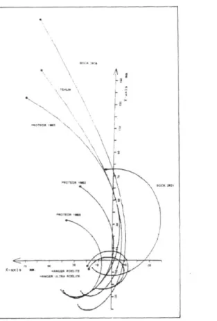
stance phase is often recoverable by individuals as the weight shifting from the amputated limb to the unaffected limb can often be altered to correct for the buckling of the prosthetic. In knee joints available in developed countries, the curve traced by movement of the CoR begins at the rear of the knee and curves forward into the knee joint before curving back to a position above and behind the knee joint. The most stable joints rarely have the CoR entering the region anterior to the joint (de Vries).
14 1
X- M1_a W1~ ~ a7tS ~ \
Figure 7: Center of Rotation trajectories for 8 of the most common knee joints available in developed countries presently. As you can see the CoR rarely if ever moves anterior to the knee joint axis, adding to the stability of the joint during stance phase. (source: de Vries)
Because of the shifting center of rotation through the loading phase, four bars offer very stable stance phase control. The single axis knee mechanism has a fixed center of rotation as opposed to a collection of instantaneous centers of rotation. A single axis knee will have its
center of rotation position posterior to the knee, in very close proximity to the joint -if not on the joint. This horizontal location of the center of rotation with respect to the knee joint will require lower energy exertion for hip torque because of the smaller moment arm during initial contact and loading response (de Vries). The four-bar design will cause much more effort in swing phase initiation, requiring more hip flexion torque than a single axis knee to initiate the bending of the joint and to activate the resulting toe clearance for the individual (de Vries; Michael). The goal of a joint design will thus be to balance this with the high stability of the four-bar design in the early loading phases and the advantage of a toe clearance during swing phase initiation.
Often, this balance can be achieved by six bar linkages. These designs enable more voluntary control during early phase (swing) and offer less resistance to flexion in late stance. However, these also consist of complicated designs and manufacture processes which can be inappropriate for developing countries (J. Andrysek).
To attempt to keep the simplistic design of the four-bar mechanism with the added stability and control of the six-bar mechanism, stance control has been attempted in several four-bar prosthetic joints for developing countries. The linkage designs and friction control mechanisms are intended to prevent the flexion of the knee until the point of desired buckling of the limb is reached in the stance phase. In addition to a more natural gait, a form of stance control -whether it is through friction elements or linkage design - can lower repeated trauma experienced by the intact limb during each step, providing a more natural and smoother weight shift during the pre-swing phase (Romo; J. Andrysek).
3.2 Jaipur Stanford Knee Analysis Results
The Jaipur-Stanford knee was designed as a non-Grashof four-bar linkage with the sum of its smallest and largest links being greater than the sum of the remaining two links. As such, typical four-bar linkage simulations available were insufficient to model the movement of the assembly. To simulate the flexion of the joint, a solid model was constructed for preliminary motion analysis. This model was constructed from the original version of the Jaipur-Stanford Knee joint. As of publication, this original version has been widely distributed with roughly 3,600 units fitted to individuals (Schwartz). A development group formed from the original Stanford course members have also recently revealed their newest design dubbed the ReMotion
Knee V3. The angles of links in the starting position and the terminal position were determined with this model through dynamic simulation of the solid model. The knee was determined to be capable of a range of motion from 0 degrees to 150 degrees where 0 degrees is defined as the neutral position when the limb is fully extended.
Figure 8: A solid model of the Jaipur-Stanford knee in the fully extended configuration (flexion angle is 0 degrees). The four-bar links are shown as the connecting lines between the individual joints of the assembly. The socket component attaches to the upper joint via a threaded mating. The pylon of the limb attaches to the bottom joint in a similar fashion.
Using the relations derived in equations (2) to (9) to determine the positions of the links, the center of rotation trajectory through the knee's entire range of motion from 0 degrees to 150 degrees was calculated by finding the intersection of the two side links (see Figure 9). The joint exhibited similar CoR trajectory behavior as that found in Figure 7.
Center of Rotation Movement of Jaipur-Stanford Knee through Full Range of Motion 1000- 500-00 -500 --1000 --1000 -500 0 500 1000 Distance, inch x102
Figure 9: The trajectory of the CoR through the Jaipur-Stanford knee through the joint's entire range of motion. The joint is
capable of a range of 0 degrees to 150 degrees, where the 0' axis is defined at full extension.
The range of motion trajectory was then broken into the eight phases of the gait cycle as defined in Burnfield. Because the amputee has no direct actuation of the joint through the swing phase, the analysis of the joint was focused on the loading phases, found at the beginning and end of the gait cycle (see Figure 10 and Figure 11). The initial positions of the four-bar linkage for each phase are shown. The red dots indicate the trajectory of the CoR travelled through the individual phase. The lines representing the pylon and the socket are shown as the bottom vertical line extending from the frame linkage and the shifting line extending from the coupler, respectively.
CoR and Joint Position: End of Initial Contact Begining of Loading Response
0
Distance, inch x10 2
Figure 10: The CoR trajectory of the Jaipur-Stanford knee in the first phase of a natural gait cycle. The knee will flex through a range from 5 degrees to 18 degrees. Here the pylon axis is assumed fixed; the socket axis flexes with respect to the fixed pylon.
In the first stage of stance phase, the center of rotation can be seen travelling from its initial position above and behind the joint to a point slightly in front of the joint. This demonstrated the loading shift of the phase and the individual begins the transfer of weight onto the limb. The knee will be most stable at the beginning of this phase as the CoR enables a torque on the knee which promotes extension of the joint. The end of the stance is of concern as the CoR is seen to move anterior of the knee. Such a translation will result in a torque promoting buckling of the knee, rotating the pylon into a flexed position up under the socket component.
10001-500 I-0 00 C X 0 -500 1 -1000 -1000 -500 500 1000
CoR and Joint Position: End of Terminal Swing
Beginning of Initial Contact
1000 (N C.) C.) C CU a, 0 500 I-0 --500 -1000 -1000 -500 0 500 1000 Distance, inch X10-2
Figure 11: The CoR trajectory of the Jaipur-Stanford knee in the final phase of a natural gait cycle. The knee will flex through a range from 0 degrees to 5 degrees; the angle at which the knee will land is shown. Here the pylon axis is assumed fixed; the
socket axis flexes with respect to the fixed pylon.
In the final phase of the gait cycle, the limb is supposed to be extended fully to initiate a stable heel strike and begin the next cycle and loading shift. The CoR calculated in this model is of concern as the position is seen anterior to the knee joint (see Figure 11). If the loading line (as shown in Figure 12) does not fall in front of this point, this slight forward positioning of the
rotation axis will result in an unstable loading as the knee will want to buckle into the socket and
behind the limb. This instability calculated may explain the reported instability experienced by amputees in the heel strike phase.
9'
Terminal Swing Initial Contact
Figure 12: Terminal Swing and Initial Contact phase positions. The loading line of the stance phase can be seen indicated in the
initial contact frame. (source: Burnfield, Phases of Gait)
4. Conclusions
The Jaipur-Stanford knee was a novel design accomplishment combining the stability and natural gait of a four-bar joint often found in developed countries with the price point of prosthetics needed for developing countries. Further iterations of the joint will benefit from the continued use of thermoplastic materials. Inexpensive hand fabrication of the joint is possible through minimal training with such materials. More advanced fabrication through injection molding of the thermoplastics is also optional to lower the cost of the joint even more in the long term.
The kinematics of the joint are fairly sufficient for its use. One point of concern is the beginning of the initial contact phase. The joint has been reportedly prone to buckling at this point in the gait cycle. This can be explained by the findings exhibited in Figure 11 in which the CoR is located slightly forward of the joint. This configuration has been shown to result in over compensation of the extension phase, in which the user often must manually push the joint back into the axis of the limb of exert high hip torques to lock the knee in extension. As such, the joint could benefit from further link optimization to improve the size and aesthetics of the joint along with trajectory path of the center of rotation to improve stability.
0
(-.o
Corrosion Resist Yield Strength Impact strength Fatigue Life Abrasion Resitant Friction Density
(low/med/hih) (@ 20'C) (low/med/high) (material w/ material)
Nylon 6 High 78 Mpa - High High 0.2-0.3 1.13 g/c-cm
Nylon 6/6 High 82.7 Mpa 10.9 J/cmA2 High High 0.43 1.14 g/c-cm
Oil-filled Nylon 6 HIGH 65.5 -76 Mpa 50 KJ/m^2 High HIGH 0.12 1.13 g/c-cm
Polypropylene, Isotactic high 40 Mpa 15.8 J/c-cm high high 0.1-0.3 0.9-0.93 g/c-cm
ABS med 42-44.8 Mpa 120 kJ/mA2 med high 0.5 1.04 g/c-cm
Polyacetyl Resin (Delrin) High 70 Mpa 60-350 kJ/mA2 High low 0.2--.35 1.42 g/c-cm
Stainless Steel High 205 Mpa 47.45 J high HIGH 0.57-0.74 8 g/c-cm
Aluminum High (AL oxide) 200 -600 Mpa 2 o low low (Al oxide) 1.05-1.35 2.70 g/c-cm
2-3E4 to 30-4OE4 N/m
Titanium High 880 Mpa 17 J High High 0.3-0.36 4.506 g/c-cm
Polyethylene (HDPE) High 26.2-200 Mpa 80 - 400 kJ/mA2 med med 0.2-0.28 0.936-1.46 g/c-cm
PVC high 44.8 Mpa 172 kJ/mA2 med high 0.23 (dynamic)-0.5(static) 1.42 g/c-cm
CD
CD
Yield Strength Fatigue Life Abrasion Resistance
Corrosion
Resistance Friction I Density I Material Costs I Total
Weight 3 3 2 2 1 1.5 3.5 Nylon 6-6 3 3 3 3 3 3 3 48 Nylon 6 3.5 4 3 3 2 3 3 51.5 Oil-filled Nylon 6 3 3 3 3 4 3 3 49 Polypropylene 2 3 3 2 3 4 4 48 Polyacetal Resin 3 3 1 3 3 2.5 3.5 45 Polythylene (HDPE) 4 2 2 3 3 3 4 49.5 ABS 2 2 3 2 2 3.5 3 39.75 PVC 2 3 3 3 3 2 3 43.5 Stainless Steel 5 3 3 2 2 1 2 44.5 Aluminum 5 2 1 3 1 1.5 2 39.25 Titanium 5 3 3 3 3 1 1 44 Material 00 cC CD 0 CD, 0 IC) CD C)
References
2013. Bhagwan Mahaveer Viklang Sahayata Samiti. 10 May 2013 <www.jaipurfoot.org>.
Andrysek, Jan. "Lower-Limb Prosthetic Technologies in the Developing World: A Review of Literature from 1994-2010." Prosthetics and Orthotics International 34.4 (2010): 378-393.
Andrysek, Jan, Susan Klejman, Ricardo Torres-Moreno, Winfried Heim, Bryan Steinnagel, and Shane Glasford. "Mobility Function of a Prosthetic Knee Joint with an Automatic Stance Phase Lock." Prosthetics and Orthotics International 35.2 (2011): 163-170.
Burnfield, Perry J. "Knee." Gait Analysis: Normal and Pathological Function. 2. SLACK Incorporated, 2010. 85-102.
Burnfield, Perry J. "Phases of Gait." Gait Analysis: Normal and Pathological Function. 2. SLACK Incorporated, 2010. 9-18.
de Vries, J. "Conventional 4-Bar Linkage Knee Mechanisms: A Strength-Weakness Analysis." Journal Of Rehabilitation Research & Development 32.1 (1995): 36-42.
"Jaipur Foot Knee/Limb." JaipurFoot. Bhagwan Mahaveer Viklang Sahayata Samiti. 10 May 2013.
<http://www.jaipurfoot.org/images/JAIPURFOOTKNEE-LIMBBROCHURE.pdf>.
Macke, Scott, Ruchi Misra and Ajay Sharma. Jaipur Foot: Challenging Convention. University of Michigan Business School, 2003.
Micheal, John W. "MEd." Clinical Orthopaedics and Related Research 361 (1999): 39-47.
Romo, H. Duane. "Prosthetic Knees." Physical Medicine and Rehabilitation Clinics of North America 11.3 (2000): 595-607.
"The JaipurKnee Project: Getting the Need Right." February 2012. Stanford Graduate School of Business. 10 May 2013.
<http://www.gsb.stanford.edu/sites/default/files/documents/JaipurKneel-GettingtheNeedRight.pdf>.
Zhang, Yi, Susan Finger and Susan Behrens. "Introduction to Mechanisms." Rapid Design through Virtual and Physical Prototyping. Carnegie Mellon University. Lecture.