HAL Id: in2p3-00620771
http://hal.in2p3.fr/in2p3-00620771
Submitted on 27 Oct 2011HAL is a multi-disciplinary open access archive for the deposit and dissemination of sci-entific research documents, whether they are pub-lished or not. The documents may come from teaching and research institutions in France or abroad, or from public or private research centers.
L’archive ouverte pluridisciplinaire HAL, est destinée au dépôt et à la diffusion de documents scientifiques de niveau recherche, publiés ou non, émanant des établissements d’enseignement et de recherche français ou étrangers, des laboratoires publics ou privés.
The LEBT Chopper for the Spiral 2 Project
A.C. Caruso, F. Consoli, G. Gallo, D. Rifuggiato, E. Zappalà, M. Di Giacomo,
A. Longhitano
To cite this version:
A.C. Caruso, F. Consoli, G. Gallo, D. Rifuggiato, E. Zappalà, et al.. The LEBT Chopper for the Spiral 2 Project. 2nd International Particle Accelerator Conference (IPAC2011), Sep 2011, San Sebastian, Spain. TUPS082, pp.1731-1733, 2011. �in2p3-00620771�
THE LEBT CHOPPER FOR THE SPIRAL2 PROJECT*
A. Caruso
#, F. Consoli
†, G. Gallo, D. Rifuggiato, E. Zappalà, INFN-LNS, Catania, Italy
A. Longhitano, ALTEK, San Gregorio di Catania, Italy
M. Di Giacomo, GANIL-SPIRAL2, Caen, France
Abstract
The Spiral2 driver uses a slow chopper situated in the common section of the low energy beam transport line to change the beam intensity, to cut off the beam in case of critical loss and to avoid hitting the wheel structure of rotating targets. The device has to work up to 10 kV, 1 kHz repetition frequency rate and its design is based on standard power circuits, standard vacuum feed-through and custom alarm board. The paper summarizes the design principles and describes the test results of the final device, which has been installed on the beam line test bench.
THE CHOPPER IN THE LEBT LINE
The low energy beam transport (LEBT) line carries continuous wave (CW), high intensity beams of protons (5mA), deuterons (5mA) and ions (1mA) with m/q=3 from the sources to the radiofrequency quadruple. The
source voltage for the three different particles are 20, 40
and 60 kV respectively, to match the RFQ input energy of 20keV/A. The layout of the injector LEBT is shown in Fig. 1. The slow chopper [1] is placed just before the beam stop in the common section of the line.
Figure 1: The injector low energy lines and the slow chopper position.
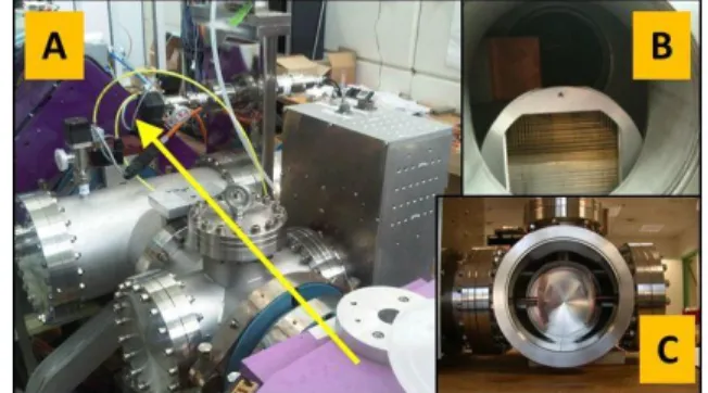
The proton/deuteron line section and the common one are presently installed at CEA Saclay to be tested before being installed in the SPIRAL2 building. The slow chopper system was moved to Saclay in June 2011 and is going to be tested with the beam in the next few months. The device assembled on the line is shown in Fig. 2. The yellow arrow, in frame A, shows the beam direction. The beam stop and the micro channel plate are shown in frame B and the deflecting electrodes in frame C.
REQUIREMENTS AND DESCRIPTION
The chopper will be used to progressively increase the beam power during accelerator tuning, to avoid hitting the
wheel spokes of rotating targets and to rapidly remove the beam in case of failure detection by the machine protection system (MPS). The tuning of the high power (200 kW) beam requires low repetition rates but a very
large duty cycle range: from 10-4 (0.01%) to CW. Rapid
transition times are required to avoid losing the beam not being perfectly deviated on the beam stop, and for fast
response to beam stop commands from the MPS.
Figure 2: The slow chopper installed in the beam line The applied voltage depends on the ion energy, on the geometry of the plates and on the beam-stop distance. The beam transversal section is quite large at the electrode position (76 mm), the equivalent hard-edge electrode length is of 160 mm and a total voltage of 17 kV has to be applied to deflect the beam onto the beam-stop. Electrode voltage of 10 kV with amplitude stability around 1-2% and rise/fall time less than 100 ns are requested.
Geometry of the electrodes
The geometry shown in Fig. 3 was chosen to obtain a flat transversal field. Field-maps were introduced in the beam dynamics simulation codes and two cases were simulated: a) one plate positively biased and one grounded and b) both plates biased with opposite voltages. No significant differences were observed in beam behaviour and the first geometry was implemented, requiring fewer electronics and vacuum components and then considered more reliable.
Figure 3:plate dimensions, the bending angle is 20°
___________________________________________
*Work supported by EU commission 7th framework project n. 212692. #[email protected]
†New affiliation: Associazione Euratom/ENEA sulla Fusione,
CP 65-00044 Frascati, Rome, Italy
Proceedings of IPAC2011, San Sebastián, Spain TUPS082
07 Accelerator Technology
T30 Subsystems, Technology and Components, Other 1731 Copyright
c○ 2011 by IP A C’11/EPS-A G — cc Cr eati v e Commons Attrib ution 3.0 (CC BY 3.0)
Slow chopp
The devel divided into prototype an prototype pl studying and voltage circu first to the fi with an ala compatible w control and SARAF, slig The entire mechanical pMechanica
Each elect copper sheet are used betw from opposi Fig. 2 (frame flange; the g flange while through conn A capacitive be usedto ch Two differ been used as with SHV-20 final version Figure 4: T From the between the The first on crimped on a is designed t line. Accordi should have rapid aging ( long time h behaviour wa Figure 5 The SHV i manufacturerper develop
opment of th two main ste d the realizati layed a funda d testing the d uit. Some of inal version, w arm board with the archi the MPS. Th ghtly modified e system can parts and the eal design.
trode is made t supported by ween the plate te sides of th e C). Each o ground electro e the polarize nector, whose pick-up is in heck the pulse rent vacuum s shown in Fig 0, while the R
. Both are stan
The two flang electric poin two feed-thro e requires an a high voltage o be matched ing to the ma worked at o (Fig. 5) was o high voltage as not affected 5: degradation is a 20kV DC r has never te
pment
he slow chopp eps: the constr ion of the finaamental role different comp them were im which have al and remote itecture of the e first prototy d and used on n be seen in electrical/elect out of a plate y a copper co es and the elec
he cross line one is support ode is connec ed plate is br ceramic is bra nserted near th presence. sealed coaxial g. 4. The proto RF-35 device ndard MDC p
ges with differ nt of view, th oughs is the a n air side SH e coaxial cabl with a high p anufacturer, b our specificati observed on t test, althou d. of the outer c C connector, bu ested it in puls per system ca ruction of the al version. The in understan ponents of the mproved from so been comp control inte e Spiral2 com ype was mov the injector be n two blocks
tronic circuits from a 3 mm lumn. No isol ctrodes are ins section show ted by its vac cted directly t
razed to the azed on the fl he feed-throu feed-through otype was equi
is mounted o roducts.
rent feedthrou he main diffe air side connec HV connector,
le. The second power rigid co both configura ions, but a so the SHV-20 a ugh the elec
coaxial surface ut it seems tha sed mode at 1 an be e first e first nding, e high m the pleted erface mputer ved to eam. s: the s. thick lators serted wn in cuum to the feed-lange. ugh to h have ipped on the ugh. rence ction. well d one oaxial ations ort of fter a ctrical e at the 1 kHz repet appli pow degr
Elec
Th high Th GSM MPS have Thre of 3 switc optim redu switc In th the m HV m elect Figu Th custo contr and t of th F Par alarm elect shap tition rate w ication. Seve er tests, hav radation has occtrical and
he electronic h voltage and t he HV module M by Behlke a S10P10/24 by e been selecte ee parallel HV 3 Ω between ch complete mizes the elec ucing stray cap ch is directly his way, the w mechanical pa module on the tric connection ure 6: The HV he control mo om built), th rol and the D the control bo he control with Figure 7: the i rticular attent m board. A c trode, detects ped to be com while the R eral weeks of ve been alr ccurred on theelectronic d
circuit is divi the alarm/cont e contains a H and a HV pow y Spellman. B ed according t V capacitors o n the output the module. T ctrical connec pacitance bec connected to whole high vol art. Fig. 6 sho e right, the cer n on the left.V module conn odule contain
e interface w DC power sup oard itself. Fig
h the main com
internal view tion was paid capacitive pick s the HV puls mpared with t RF 35 is gi f continuous eady perform e second one.
design
ided into two trol. HV switch, the wer supply 10 Both off-the-to the initial of 3nF and a of power su The new RF ction with the cause the outp the ceramic ltage module ws the interna ramic feed-thr nected with fe ns the alarm b with the Spira pplies for the g. 7 shows the mponents. of the control d to the reali k-up, facing se signal. This the driving T iven for RF 24-hour full med and no modules: the e HTS 151-03 0kV/1mA, the shelf devices requirements. shunt resistor upply and the feed-through e HV module, put of the HV feed-through. is attached to al view of the rough and the
eed-through. board (totally al2 computer e HV module internal view l module ization of the the polarized s signal is re-TTL signal to F l o e 3 e s . r e h , V . o e e y r e w e d -o
TUPS082 Proceedings of IPAC2011, San Sebastián, Spain
1732 Copyright c○ 2011 by IP A C’11/EPS-A G — cc Cr eati v e Commons Attrib ution 3.0 (CC BY 3.0) 07 Accelerator Technology T30 Subsystems, Technology and Components, Other
check the pro probe, conne but there wou presence of h used as a pro about the HV maintenance also in local the front pa standard sign the high volt
The block design with connections w Figure 8: B
EX
The direct HV switch h which is less capacitance a feed-through and reduced full power te for several summarized Maximu Maximu Rise/fal Maximu Nomina Duty cy Duty cy Max bea MPS ala oper working ected to the airuld be a rema high voltage o otection syste V on the defl and/or verifi mode: a self anel of the c nal of 1 kHz, age can be do diagram in F the internal with the Spira
Block diagram
XPERIME
connection b has notably red
s than 70 pF: and about 40 h. This has inc
the rise/fall ti ests have been weeks. The in Table 1. Table 1: ex um Voltage um Current l time um frequency al frequency ycle (≤ 513 Hz ycle @ 1kHz am stop delay arm delay of the whole r-side feed-thr ining margin on the plate. T em, so it is ne flecting electro fication operat f-test push bu control modu 50% duty cy one through a p Fig. 8 summar sub-modules al2 remote con
m of the slow
NTAL RES
etween the fe duced the tota 30 pF due to pF due to the creased the op me of the syst n performed on main experim xperimental re 10 kV 1 mA ≅ 15 n > 1.5 k Up to z) 0.01-9 0.1-99 y ≤ 400 ≤ 400 system. A res rough can be of doubt abou The chopper is ecessary to be odes. Some u tions can be utton is install ule. It produc ycle. The setti
precision knob rizes the elect s and the ext ntrol interface chopper syste
SULTS
ed-through an al load capacit o the switch o electrodes an perating frequ tem. Uninterru n the slow cho mental result esults ns kHz 1.0 kHz 9.99% .9% ns ns istive used, ut the s also e sure useful done led in ces a ng of b. tronic ternal e. em. nd the tance, output nd the uency upted opper s are T Fig Fig kV: frequ HV pick-alarm Fig. high green oper is sen F Th the f is re signi whic are w relia [1] he full power gure 9: The ch g. 10 shows a rise and fa uency of 1.3 signal is in y -up signal in m board pushe 10 (D) the d h voltage to 10 n) switching ration is ≤ 400 nt to the mach Figure 10: a se he present ver frame of the S eady for beamificantly impr ch has been se well beyond re ability and easy
M. Di Giacom chopper for t BC, Canada,
test bench set
hopper princip series of osci all time of 1 kHz (C); an yellow, the T n purple (A,B es the HV to disconnection 0 kV,despite off the HV. 0ns and at the hine protection equence of osc
CONCLU
rsion of the s Spiral2 PP Eur m tests on th roved with re ent to SARAF equired values y maintenanceREFERE
mo et al,” Prel the spiral 2 p Sept-Oct 2008 t-up is shown ple schematic illoscope acqu 13-15ns (A,B alarm simulat TL driver in B,C). For an 10 kV, to stop of the pick-u the TTL driv The delay o same time an n system. cilloscope acqUSION
low chopper, ropean cooper he LEBT line espect to the F (Israel) and s. The design e.NCES
liminary desig project”, Linac 8, THP046, p in Fig. 9. test bench uisitions at 10 B); repetition tion (D). The blue and the ny failure the p the beam. In up pushes the ving signal (in of this safety n alarm signal quisitions. developed in ration project, . It has been first version, performances aims for highgn of the slow c08, Victoria, . 891 (2008). 0 n e e e n e n y l n , n , s h w ,
Proceedings of IPAC2011, San Sebastián, Spain TUPS082
07 Accelerator Technology
T30 Subsystems, Technology and Components, Other 1733 Copyright
c○ 2011 by IP A C’11/EPS-A G — cc Cr eati v e Commons Attrib ution 3.0 (CC BY 3.0)