HAL Id: in2p3-00169961
http://hal.in2p3.fr/in2p3-00169961
Submitted on 5 Sep 2007
HAL is a multi-disciplinary open access
archive for the deposit and dissemination of
sci-entific research documents, whether they are
pub-lished or not. The documents may come from
teaching and research institutions in France or
abroad, or from public or private research centers.
L’archive ouverte pluridisciplinaire HAL, est
destinée au dépôt et à la diffusion de documents
scientifiques de niveau recherche, publiés ou non,
émanant des établissements d’enseignement et de
recherche français ou étrangers, des laboratoires
publics ou privés.
Irradiation control of the ”SPIRAL” target by measuring
the ion beam intensity via a fast current transformer
P. Anger, C. Doutressoulles, C. Jamet, T. André, W. Le Coz, E. Swartvagher,
M. Ozille
To cite this version:
P. Anger, C. Doutressoulles, C. Jamet, T. André, W. Le Coz, et al.. Irradiation control of the
”SPIRAL” target by measuring the ion beam intensity via a fast current transformer. 7th European
workshop on beam diagnostics and instrumentation for particle accelerators, Jun 2005, Lyon, France.
Joint Accelerator Conferences Website, pp.208-210, 2005. �in2p3-00169961�
IRRADIATION CONTROL OF THE “SPIRAL” TARGET BY MEASURING
THE ION BEAM INTENSITY VIA A FAST CURRENT TRANSFORMER
P. Anger, C. Doutressoulles, C. Jamet, T. André, W. Le Coz, E. Swartvagher, M. Ozille
Grand Accélérateur National d’Ions Lourds (GANIL), Caen, France
e-mail : anger@ganil.fr
Abstract
In order to obtain a more precise control on the irradiation of the targets of the “SPIRAL” installation, a new criterion of safety must be respected. To control this latter, an AQ system has been put in operation and more specifically a new device has been set up in order to measure the ion beam intensity and to calculate the number of particules per second. This value can then be integrated over time. This device consists of two Fast Current Transformers integrated in a mechanical unit placed in a vacuum chamber. These sensors reproduce the image of the pulsed beam at 10MHz and we take from the amplified signal of each sensor, the amplitude of the 2nd harmonic. Each one of these amplitudes is detected by a Lock-in Amplifier, which is acquired via a real time industrial controller. The intensity is calculated by the Fourier series relation between the amplitude of the 2nd harmonic and the average intensity. These equipments can be remotely tested by integrating a test turn on the sensors. They are redundant. The accuracy of measurement is estimated taking into account the variation of beam, of the environment and of the installation
INTRODUCTION
The SPIRAL unit generates a radioactive ion beam by irradiating an ECS “Ensemble Cible-Source”
(Target-Ion Source) with a high energy ion beam.
GANIL is a facility submitted to approval, and the irradiation mode of targets is regulated by the safety authorities. At present, the target irradiation is limited by a safety criterion of 15 days of use , independently of the irradiating beam characteristics (ion species, power and risks linked to the operation of the accelerators). A request for modification of this criterion has beenformulated to the safety authorities. The maximum irradiation time authorised should depend on the irradiating beam type and of its intensity, the new criterion being that the total number of ions received by the target (integrated flux) should not exceed a certain level, function of the radiological risk.
In order to control this new criterion, the CICS project (Contrôle de l’Irradiation de la Cible de
SPIRAL) (Irradiation Control of the SPIRAL Target)
has been issued: it will require a measurement system and a reliable control of the beam intensity which will, at any time, show both the instantaneous and the integrated beam intensity for each target. The intensity means the number of ions per second.
DESCRIPTION OF THE SYSTEM
The system consists of two sensors measuring the intensity of the primary beam irradiating the ECS
(Target- Ion Source) and returning an electric signal
proportional to the intensity. A dedicated chain of measurement will handle the signal of each sensor so that they can be digitized by a computing system. This dedicated and autonomous computing system will be able to test the two instrumentations and handle any malfunctions. Using an user interface, this computing system will receive the necessary information from the primary beam, the identification of the ECS and the new criterion in order to measure the intensity of the beam, calculate the number of particles per second and integrate the number of ions stopping in the target. The computing system records the data related to the irradiation of each ECS on two reliable and permanent data carriers. It cuts off the beam either when a malfunction occurs or when the target has received the maximum dose (new safety criterion).
PRINCIPLE OF THE MEASUREMENT
OF THE BEAM INTENSITY
The beam intensity is obtained by measuring the magnetic field generated by the pulsed beam (fig.1) with a Fast Current Transformer of 10 turns.
POT028 Proceedings of DIPAC 2005, Lyon, France
The current transformer (fig.2, fig.3) generates an image signal of the beam intensity to a treatment chain ; then, the amplitude of the second harmonic of the signal is detected by a Lock-in Amplifier. This Lock-in Amplifier is a Stanford Research Systems “SR844” model (fig.4). This detection is based on the principle of synchronous detection. This amplifier is locked onto the 2nd harmonic by a RF reference in order to measure the module of the 2nd harmonic. The average value of the intensity is calculated by the relation between the 2nd harmonic amplitude and the average value in the Fourier expansion :
2
)
4
(
1
)
2
cos(
2
2 2 2 0a
F
F
a
a
≅
−
=
τ
τ
π
ifF
1
<<
τ
This measuring equipment is doubled (fig.5) in order to ensure an active redundancy which guarantees the validity of the measurement. The dispersion (D) is calculated and must be lower than a maximum value:
(
)
max
)
(
)
(
)
(
)
(
2
D
t
I
t
I
t
I
t
I
D
B A B A≤
+
−
×
=
The measuring equipment is calibrated in order to establish the global accuracy of the measurement and therefore to deliberatly overestimate, by programming, the calculated intensity :
∆ + × + = I t I t I t I A B I 1 2 ) ( ) ( ) (
The measurement range of the beam intensity is 10nA/50µA.
An additional test turn was integrated into the Fast Current Transformer to test the measuring equipment (fig.5). Sending a 2F sinusoidal signal allows testing of the availability of the system.
MECHANICAL INTEGRATION
The sensor is installed in the L4 beam line a few meters in front of the SPIRAL target (fig.6).
The two sensors are integrated in one block which is placed in the vacuum chamber. This mechanical device is operated at a pressure of 10-6 Pa and has a leak rate better than 10-10Pa.m3/s (for He). (fig.7)
Figure 3: Picture of 2 Fast Current Transformers
BERGOZ FCT-082-10:1-WB IS = IBeam /Number of loops
R V (Secondary) IBeam (Primary) IS
Figure 2: Toric transformer
Figure 4: Lock-in Amplifier “SR844”
Test B Test A Beam Treated Intensity measurement by controller A B Control & Tests status Lock-in amplifierA 30 MHz Filter Lock-in amplifier B 30 MHz Filter RF Signal Référence G1 A Accelerator Room Instrument Room G1 B G IF IS Level adaptator Treated Intensity measurement by controller
Figure 5 : Instrumentation Synoptic
Test signal generator
Figure 6: Beam line
Line 4 High Energy
Mechanical
Integration Beam cut-off
Figure 7: Mechanical assembly of the dual sensor
Proceedings of DIPAC 2005, Lyon, France POT028
DESCRIPTION OF THE COMPUTING
SYSTEM
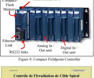
It is basically composed of a real time industrial controller : Compact Fieldpoint (fig.8) from National Instruments. It is autonomous, has its own operation system and is programmed under Labview. The system must obtain the detected intensity of the beam, calculate the particle fluency, stop the beam with a beam stopper block if the level is exceeded, or in case of malfunction. It will record the irradiation history on a local memory and provide a link to the user PC. The system will also have a user interface in order to configure the system and to keep the users informed (fig.9).
QUALITY ASSURANCE
The study, implementation and operation of this system need to satisfy quality requirements in order to control the new safety criterion. The intensity measurement veracity, the malfunction management and the overall reliability were taken into account from the beginning. For example, the uncertainty of the measurement chain will be treated whatever the beam frequency, pulse length, subset operating temperature, and also which units or refills are installed. To calculate the accuracy of each unit, a testing coaxial line was used for FCT (fig.10) and a test bench with a temperature-regulated chamber was developed (fig.11).
CONCLUSION
This project is nearly completed ; it is awaiting starting-up authorisation for the validation of the concept (control system of the new safety criterion) by the safety authorities. It will allow better management of target irradiation by lowering the number of ECS
(Target-Ion Sources) used every year. It will also allow
us to operate and handle an AQ instrumentation system while assuring absolute accuracy of the measurement.
REFERENCES
[1] S. Faure, « Limite d’irradiation d’un ECS de SPIRAL », GANIL 2003, SPR213B
[2] P. Anger and the Project Team : C. Doutressoulles, M. Ozille, JF. Rozé, B. Jacquot, M. Dubois, S. Faure, F. Bucaille, C. Mauger, JC. Deroy, «
Cahier des Charges et des Clauses Techniques du projet CICS » GANIL 2003,
P-CICS-043-CdCCT-A.
[3] M. Lieuvin et al., Commissioning of SPIRAL, the
GANIL radioactive beam facility, 16th Int. Conf. On Cyclotrons and their Applications. Michigan 2001.
Figure 9: User Interface
Figure 8: Compact Fieldpoint Controller Analog In /
Out unit Digital In /
Out unit Autonomous CPU Ethernet Link Compact-Flash Memory RS232 links
Figure 11: Temperature testing device Figure 10: Testing coaxial line for FCT
POT028 Proceedings of DIPAC 2005, Lyon, France