Development of a Compensation Chamber for use in a Multiple
Condenser Loop Heat Pipe
by
Nicholas Albert Roche
Submitted to the
B.S., Mechanical Engineering
Carnegie Mellon University, 2009
Department of Mechanical Engineering in
the Requirements for the Degree of
Partial Fulfillment of
Master of Science in Mechanical Engineering at the
MASSACHUSETTS INSTITUTE OF TECHNOLOGY June 2013
ARCHNE
ASSiAiiUSE5TT; NSTITUTEjO, T
© 2013 Massachusetts Institute of Technology
All rights reserved.
Signature of Author ...
...
Department of Mechanical Engineering
May 10, 2013
C ertified by ... ,...
. .
John G. Brisson
Professor of Mechanical Engineering
Thesis Supervisor
A ccepted by ...
. . ...
David Hardt
Chairman, Department Committee on Graduate Students
Development of a Compensation Chamber for use in a Multiple
Condenser Loop Heat Pipe
By
Nicholas Albert Roche
Submitted to the Department of Mechanical Engineering on May 10, 2013 in partial fulfillment of the
requirements for the degree of
Master of Science in Mechanical Engineering
Abstract
The performance of many electronic devices is presently limited by heat dissipation rates. One potential solution lies in high-performance air-cooled heat exchangers like PHUMP, the multiple condenser loop heat pipe presented here. This device features a number of design improvements that lead to significant increases in performance relative to state of the art heat exchangers. In this work, a compensation chamber is developed and implemented to ensure the operational stability of the device across a wide range of operating conditions.
A computational model of the device was developed using COMSOL Multiphysics v3.5a to allow for design optimization and performance evaluation. The accuracy of this computational model was established by comparing simulation results to experimental data. Analytical models were used to identify operating points of interest, which were simulated to compare the
performance of various designs. The final design featured reduced thermal resistance between the vapor in the evaporator and the compensation chamber, and increased thermal resistance between the compensation chamber and the ambient air relative to past designs. This design reduced the risk of condenser flooding and evaporator dry out, improving the operational
stability of the device. This design was implemented into a ten-condenser prototype, where experiments validated its performance. The compensation chamber did not require any electrical heaters, reducing the power consumption of the device and increasing its COP. Finally, general recommendations and guidelines are presented for use during the design process of future
compensation chambers.
Thesis Supervisor: John G. Brisson
Acknowledgements
My time at MIT has been extremely rewarding, as I have been part of an incredible place that has allowed me to develop academically, professionally, and personally. However, none of my work would have been possible without the support and contributions of many of my friends, family, and teachers.
First, I would like to thank my family for their years of support and love: my loving parents Marie-Claire and Geoffrey, my sister Marie-France, and my brothers Alexandre and Christian. Without them I would have never been able to come to MIT and accomplish so many of my dreams, and their continued faith in my abilities has helped me through even the toughest of times.
Professor John Brisson has been my research advisor these last two years and has contributed greatly to my growth as an engineer. His abilities as a researcher, teacher, and mentor are unparalleled, and I thank him for consistently pushing me to achieve my best. In particular, his attention to detail in all areas, especially writing, has set him apart from his peers.
His guidance has helped me to grow immensely.
I have been incredibly fortunate to work on PHUMP, the unfortunately named heat exchanger that is the focus of this thesis. The team that has brought this project to life are some of the smartest people that I have ever worked with, and have helped to make this project a pleasure to be a part of in spite of its challenges. In addition to my advisor, Professors Evelyn
Wang and Jeffrey Lang have worked tirelessly on all fronts on this project, and their efforts are greatly appreciated. Dr. Teresa Peters and Dr. Martin Cleary have provided excellent support and mentorship throughout the course of the project in their role as post docs, and their guidance has helped me greatly. UROPs Jay Sircar and Kristyn Kadala gave valuable assistance in many areas
of this project, and I wish them the best in their careers. My fellow graduate students Arthur Kariya, Daniel Hanks, and Wayne Staats are friends that I am honored to call colleagues; I have greatly respect their integrity, dedication, and abilities, and I cherish the camaraderie and
friendship that we developed while working on this project. I also thank the Defense Advanced Research Projects Agency, the Microtechnologies for Air Cooled Exchangers program, and its managers Dr. Thomas Kenny and Dr. Avram Bar-Cohen, for making this work possible.
The Cryolab and its denizens have provided me with a great place to do research. I'd like to thank all of my labmates (Phil Knodel, Victoria Lee, Martin Segado and Jake Hogan) for making this place so enjoyable, and Doris Elsemiller, Michael Demaree, Paul Finn, and Don
Strahan for helping it to run so smoothly. I'd also like to thank Mark Belanger of the Edgerton Machine Shop for taking the time to answer my numerous questions with incredible patience. My peers in the Film Club and EVT have helped to make my time here enjoyable outside of mechanical engineering.
Lastly, I'd like to thank all of my friends at MIT for making these last two years be some of the most fun of my life. I've always known I can count on them to provide friendship, support, and most importantly, laughter during the many periods of difficulty and duress these last two years. While our time together may have been momentary, I know that these memories and friendships will be with us forever, as we ride off into the friscalating dusklight.
Table of Contents
A bstract... 3
A cknow ledgem ents ... 4
Table of C ontents ... 5 List of Figures... 7 List of Tables ... 10 Chapter 1: Introduction ... 12 1.1 M otivation ... 12 1.2 Background... 13
1.3 PH U M P: D escription of the System ... 17
1.3.1 H eat Pipe Functionality... 18
1.3.2 The PHU M P D esign ... 20
1.4 The N eed for a Com pensation Cham ber ... 23
1.4.1 Condenser Flooding ... 24
1.4.2 Evaporator Dry-Out ... 25
1.4.3 Heat Pipes, Loop Heat Pipes, and Capillary Pumped Loops... 28
1.5 Prototype D evelopm ent ... 29
1.6 Literature Review ... 31
1.7 Thesis Outline... 32
Chapter 2: Design of the Compensation Chamber... 33
2.1 Compensation Chamber Performance Requirements... 33
2.1.1 Therm al Requirem ents... 33
2.1.2 M echanical Requirem ents... 38
2.2 D esign Overview ... 40
2.3 D esign M ethods and Techniques... 41
2.3.1 1-D Therm al Resistance Netw ork... 41
2.3.2 Com putational Sim ulation ... 44
2.4 Sim ulation Results and D esign Optim ization... 57
2.5 Com ponent M anufacturing... 58
2.6 Chapter Sum m ary ... 66
Chapter 3: Experim ental R esults ... 67
3.1 Testing Procedures and the Mk I and Mk II Prototypes... 67
3.2 Testing of the Mk 1I1a Prototype and Performance Comparison ... 71
3.4 Mk IlIb Testing and Performance ... 79
3.5 Chapter Summary ... 83
Chapter 4: Conclusions ... 84
4.1 Compensation Chamber Design ... 84
4.2 Prototype Characterization... 85
4.3 Application Considerations and Design Recommendations ... 86
4.4 Future W ork... 87
4.5 Concluding Remarks ... 88
List of Figures
Figure 1-1: Ranges of heat fluxes that can be cooled by various physical phenomena. Figure taken from Staats [1]; originally adapted
from
[2]... 14 Figure 1-2: A typical air-cooled heat exchanger, the NZXT Respire T40. Heat transported from the CPU to afin array that features forced convectionfrom
a modular fan. While simple, these designs feature poor thermal resistance and system efficiency (Image takenfrom
[4])... 15 Figure 1-3: PHUMP, the high performance air-cooled heat exchanger developed in this work Heat is input at the base of the device, where it is transported to condensers that act as fins. This heat is dissipated to the air via impellers interdigitated between the fins driven by a low profile electric m o to r. ... 1 7 Figure 1-4: Schematic of traditional heat pipe operation. The device is typically made of copper, with copper or stainless steel used as the wicking structure. The choice ofworking fluid isdictated by operating conditions, but at room temperatures ammonia and water are the most p op u la r ch o ices... 19 Figure 1-5: The functionality of a Loop Heat Pipe is very similar to that of a traditional heat pipe, although the liquid and vapor transport lines are separated and a wick is used in the
evap o ra to r a lo n e... 2 1 Figure 1-6: Schematic of PHUMP, including the evaporator and a single condenser. The
Compensation Chamber is constructed from a coarse copper sinter, the Insulating Layer
from
Monel sinter, and the High thermal conductivity wick uses afine copper sinter... 22 Figure 1-7: Advancing and receding menisci at the liquid-vapor interface in the condensers ofPHUMP. Receding menisci have been shown to be more stable than advancing, and is the
preferred configuration for stable operation. Figure taken from Hanks [5]. ... 24 Figure 1-8: Flooding of the condenser occurs when the liquid pressure exceeds the vapor
pressure by an amount greater than the wick structure can support. Without the presence of a wicking structure, the transition to flooding occurs more abruptly. Figure taken from Hanks [5]. ... 2 5 Figure 1-9: The beginnings of evaporator dry-out, as vapor forces its way through the condenser wick and entrains itself in the liquid line. Figure taken
from
Hanks [5]... 27Figure 1-10: The three prototypes developed for the PHUMP project, (a) the single condenser
Mk I prototype, (b) the six condenser Mk II prototype, and (c) the ten condenser Mk III
p ro to typ e. ... 3 0 Figure 2-1: Schematic of loop heat pipe operation showing evaporator, the uppermost and lowermost parallel condenser sections, compensation chamber, and liquid and vapor lines. Blue regions represent liquid flow, red and pink vapor, while airflow is shown with the green arrows. ... 3 4 Figure 2-2: Schematic of the evaporator used in previous prototypes... 40 Figure 2-3: A 1-D thermal resistance network was used as afirst order model of the evaporator. The compensation chamber temperature is set by the relative thermal resistances of conduction
from
the vapor channels at the evaporator base and convectionfrom
the impeller above theevaporator. Vapor is in pink, vapor flow in red, and liquid in blue ... 42 Figure 2-4: Boundary conditions used on the evaporator during COMSOL modeling. Liquid and vapor are in light blue and pink, respectively... 46
Figure 2-5: Airflow (green) between the evaporator and condenser; the evaporator surface temperature is assumed uniform at Ts, the condenser at Tvapor. This air has a radial
tem p erature distribution. ... 48 Figure 2-6: Schematic of condenser interior. The subcooling region ('Subcooling Plates')
provides a region where sensible cooling of the liquid can occur. Figure adapted
from
Hanks [5] ... 5 0Figure 2-7: Energy transfer in a differential element (width dx, height t) cross section of the subcooling region. Heat transferred due to convection or conduction are shown with red arrows,
while the blue arrows represent energy transfers in and out due to liquid flow. ... 51 Figure 2-8: Predictions of two 'thermalfin' subcooling models (dotted and dashed lines)
compared to experimental data (triangles) for three fan speeds (colors). Note the poor
agreem ent between data and m odel... 53
Figure 2-9: The geometry of the subcooling region used in the condensers, shown in (a), features a length L that varies considerably along its width. This was instead modeled in (b) as afin of constant length Leff and equivalent width W has the same overall area... 54 Figure 2-10: Predictions of the 'effective length' thermal fin subcooling model (dashed lines)
compared to experimental data (triangles) for three fan speeds (colors). Note the improved agreement between data and model when compared to that of Figure 2-8... 54 Figure 2-11: Temperature profile in the mid plane of the compensation chamber from a
completed COMSOL simulation. The heat load into the evaporator was 1125 Wand the fan speed was 6000 RPM Note the effect of subcooled liquid near the liquid lines on the temperature p rof ile in th e d evice... 5 7
Figure 2-12: Pressure difference at the liquid-vapor interface in the condensers (P2-P3 in Figure
2-1) as a
function
of operating point for a variety of compensation chamber designs. Theflooding and vapor burst through limits (from [5]) are indicated by dashed red lines... 59 Figure 2-13: The final evaporator and compensation chamber design (Mk III at right) compared
to the original Mk I design at left (enlarged for detail). Note the thinner layer of Monel sinter;
1.8 mm has been replaced with coarse copper sinter. Vapor and liquid lines and flows have been
o m itted h ere. ... 5 9
Figure 2-14: Predicted pressure difference across liquid-vapor meniscus in condensers (P2-P3) at
various heat loads and
fan
speeds for the 2.2 mm Monel, 1.8mm Cu insulating layer design. The dashed lines indicate the limits for both condenser flooding and vapor penetration... 60 Figure 2-15: The two impellers used in the final PHUMP prototype. Impeller 1 is used directly above the evaporator and compensation chamber and offers approximately 60% of theperformance of impeller 13 (used elsewhere in the device). This specific convective performance helps to precisely set the compensation chamber temperature. Figure adapted from Staats [1]. 60 Figure 2-16: Fabrication process of the evaporator. Ofparticular interests are steps 1 and 2, the sintering of the compensation chamber and insulating layer. Figure adapted
from
Kariya [6]. 63 Figure 2-17: Components of the evaporator fabrication. The completed compensation chamber wick and the graphite mold used in its sintering process are shown in A and B respectively. PartsC and D show the equivalent parts used in the vapor channels. The monel case (or frame) and
the copper base plate of the evaporator are depicted in parts E and F. Figure adapted from K a riy a [6] . ... 6 4 Figure 2-18: Cross section of an evaporator used in an earlier prototype. Note the thickness of the insulating wick and its homogenous Monel composition. Figure adapted
from
Kariya [6].. 65Figure 2-19: Compensation chamber wick (in brown) with existing liquid channels shown in blue. To increase the volume of these channels, eight 2.5 mm (0.1 in) wide spacers are placed in the graphite mold at locations shown in red... 65 Figure 3-1: Schematic of the heat pipe cycle in both A) LHP and B) CPL operation modes. Pink and light blue regions indicate liquid and vapor, respectively, while wicks are shown with the hatched sections and electric heaters on the reservoir are orange. Note the change in location of the two-phase region between the two operational modes. Figure adapted from Kariya [6]. .... 68 Figure 3-2: Schematic of the heat pipe cycle for evaporator testing. Note the presence of the additional subcooler, a heat exchanger used to provide additional sensible cooling to the liquid prior to returning to the evaporator. Figure sourced from Kariya [6]... 70
Figure 3-3: The heat pipe setup used for evaporator testing prior to device assembly. Image A) shows a labeled top down-view of the components without the entire condenser, and B) shows the entire cycle. Figure adaptedfrom [6]... 72 Figure 3-4: Temperature difference between the compensation chamber and the vapor channels for the M k IIla evap orator ... 75
Figure 3-5: Temperature difference between the compensation chamber and the vapor channels for the Mk I and Ia evaporators as a
function
ofvapor temperature... 76Figure 3-6: Temperature difference between the compensation chamber and the vapor channels for the Mk I and IIla evaporator as a
function
of heat load... 77Figure 3-7: Thermal performance of the Mk IfIb prototype for operation at 5000 and 6000 RPM The slope of these lines represents the thermal resistance at eachfan speed These are the best results from a series of tests and could not be achieved repeatedly... 80 Figure 3-8: A defect in one of the condensers forms when sinter is removed
from
the subcooling region during the machining process and a void is created Recently condensed liquid vaporizes here and serves to set the liquid pressure within the device, flooding condensers, increasingthermal resistance, and leading to unstable performance... 81 Figure 3-9:Flow reversion in the k III prototype; impellers are shown in blue. Nominally, air
enters through the axial inlet at the top and is pumped out radially by the impellers, as shown by the dashed green lines. However, as the impeller above the evaporator features reduced
pumping power, it may be overwhelmed by the pumping power of the other impellers, causing air to flow inwards radially over the evaporator (dashed red line). ... 82
List of Tables
Table ]-]:Performance targets of the DARPA MACE program; typical values of the same metric for a state of the art heat exchanger are provided for comparison (typical values taken from [1]). ... 1 5
Table 1-2: Performance and
features
of the three PHUMP prototypes... 30Table 2-1: Values ofparameters used in calculation of operating limits... 38
Table 2-2: Values ofparameters in energy equation within evaporator... 42 Table 2-3: Values of boundary conditions applied to COMSOL model of evaporator for a typical op era tin g p o in t... 4 6 Table 2-4: Values ofparameters in energy balance on subcooling region... 52 Table 2-5: Material properties applied to sinter and Monel in COMSOL simulations. ... 55
Chapter 1: Introduction
1.1 Motivation
In the last 20 years, the performance of computers has increased dramatically due to numerous advances in processor technology. With these advances has come a need for similar
improvements in thermal management technology to dissipate the increasing heat load that accompanies this performance increase. However, the rate of advance of these two fields has not proceeded equally, with the state of thermal management lagging behind that of computing power. So large is this gap that thermal management now represents the critical bottleneck to
improving computing performance. This need is felt across a wide range of fields, from personal computers and commercial server installations to x-ray imaging and laser generation systems. In all applications, it is critical that heat loads be dissipated efficiently to prevent damage to the device being cooled due to excessive temperatures. Additionally, as the cooling needs of thermal systems have increased, so too has the power consumption of their cooling systems, resulting in a significant increase in energy use related to electronics cooling. This increase is only expected to continue; it is estimated that the cooling needs of data centers alone could reach several percent of total US power consumption by 2025 [20]. As such, there is an immediate need to
improve both the performance and efficiency of thermal management techniques.
To this end, the United States Defense Advanced Research Projects Agency, DARPA, has issued grants with the expressed goal of significantly advancing the state of thermal
management. This work has been supported by one such grant program: Microtechnologies for Air-Cooled Exchangers (MACE). This particular program targets air-cooled heat exchangers,
this thermal management technique. This work details the development of a component within PHUMP, a device designed by a group of researchers at MIT to meet and exceed these
performance targets.
1.2 Background
A wide variety of thermal management solutions are presently in use, capable of dissipating a range of heat loads for use in numerous different applications. These solutions can be classified by the physical phenomena used to dissipate heat from a device. A discussion on the relative merits of each of these phenomena is provided below, while Figure 1-1 illustrates the ranges of heat fluxes that can be managed by each.
The simplest and most common method of electronics thermal management utilizes natural or forced convection with air as a working fluid. A typical air cooled heat-exchanger, the NZXT Respire T40, is shown in Figure 1-2 below. Nearly all desktop computers have relied on this method as a means of thermal management, with a fan forcing air over an array of fins (often made of aluminum) connected to the central processing unit. This method offers acceptable performance for many applications and is attractive due to its low cost and simple, robust design. However, this method is incapable of dissipating heat fluxes in excess of 10 4 W/m2, a figure
commonly exceeded by many of today's electronic devices. This method is limited by high thermal resistances caused by inefficiencies of traditional fin designs and fan architectures. These systems are also electrically inefficient due to design limitations inherent to the fans used, as discussed in Staats [1].
102 103 10 10 10
Heat Flux (W/n)
Figure 1-]: Ranges of heat fluxes that can be cooled by various physical phenomena. Figure taken
from
Staats [1]; originally adaptedfrom
[2].When additional cooling power is required, single phase liquid cooling systems are used. A simple liquid manifold is connected to the CPU (or other hot spots) to transfer heat to a fluid. This fluid is then transported to a liquid-to-air heat exchanger, where heat is transferred to the air via forced convection. While this design offers increased performance, additional components
are required that increase the complexity of the system. Most importantly, this configuration introduces the risk of fluid leaks into the electronic system; this can cause electrical short
circuiting and system failure or destruction. As such, many manufacturers and users are reluctant to make use of this solution. Additionally, this method requires significant energy input to the
fluid pump and fan that leads to system inefficiency.
The highest performance devices make use of two-phase cooling systems to mitigate hot spots or manage high or ultra-high heat fluxes (defined as 106 and 109 W/m2, respectively).
Techniques used include liquid-immersion cooling, spray and jet-impingement cooling, and flow boiling systems, which are outlined by Mudawar [3]. Although they allow for increased
performance, these systems are subject to the same shortcomings and risks as single phase fluid systems, often requiring great complexity and cost. These systems are also similarly inefficient,
Figure 1-2: A typical air-cooled heat exchanger, the NZXT Respire T40. Heat transported
from
the CPU to afin array that features forced convectionfrom
a modular fan. While simple, these designs feature poor thermal resistance and system efficiency (Image takenfrom
[4]).and difficult to maintain over the life of a typical device. As such, they are reserved for situations where their use is deemed absolutely necessary.
There exists a significant opportunity in the thermal management space for a device that combines the simplicity, safety, and reliability characteristic of air-cooled heat exchangers with the advanced performance capabilities of liquid cooling systems. The DARPA grant that has fimded this research seeks to do just this, and features performance targets listed in Table 1-1 below. Two parameters are of particular interest: thermal resistance and coefficient of
performance (or COP).
Table ]-1:Performance targets of the DARPA MA CE program; typical values of the same metric for a state of the art heat exchanger are provided for comparison (typical values taken from [1]).
Performance Metric DARPA MACE State of the art Goal
Heat Load [W] 1000 100-200
Overall Thermal Resistance 0.05 0.2
[0C/W]
Coefficient of Performance 30 15-50
Thermal resistance measures the effectiveness of a thermal management method and comes from an analogy with electric circuits. Just as the current (I ) in an electrical circuit is related to the voltage drop or potential difference that drives it (AV) by an electrical resistance (Ohm's Law), the rate of heat transfer (Q ) in a thermal circuit is related to the temperature difference ( AT ) that drives it by a thermal resistance ( Rh ). This can also be stated as
AT
1h =.1.1
Thus for a given temperature difference, a thermal management method with a low thermal resistance will be capable of dissipating more heat than a method with a higher thermal resistance.
COP provides a measure of cooling power efficiency and is the ratio of heat transfer rate or cooling power to the electrical power (W ) required to operate the heat exchanger
COP= 1.2
Thus a device with a COP of 10 will dissipate a thermal load of 10 W for 1 W of electrical power input; unlike thermal resistance, this parameter is dimensionless. As the amount of cooling required for processor performance has increased, so too has the energy input required to achieve this cooling load without resorting to excessive chip or device temperatures. Advances are also required in the area of COP if these electrical needs are to be reduced as computing power increases. To this end, this work targets improvement in this area as well in more traditional metrics like thermal resistance and heat dissipation.
1.3 PHUMP: Description of the System
To achieve these advanced performance metrics, the team at MIT has developed a high performance air-cooled heat exchanger, call PHUMP and shown in Figure 1-3. Heat,
Q,
is transferred to the device through its base, where the heat is transported to the fins by a loop heat pipe mechanism. Ambient air is drawn into the device axially by impellers interdigitated between each fin layer. The air then travels between the fins, cooling them, before exiting radiallyoutward. The impellers rotate on a common shaft driven by a low profile electric motor housed at the top of the device.
Two critical innovations are responsible for PHUMP's exceptional performance. First, it utilizes a loop heat pipe to efficiently transport heat to the planar condensers that also function as
Cool Air In U Motor Impeller Condenser g Vertical Fluid Connector Evaporator
Heat Transfer (O)
Figure 1-3: PHUMP, the high performance air-cooled heat exchanger developed in this work. Heat is input at the base of the device, where it is transported to condensers that act as fins. This heat is dissipated to the air via impellers interdigitated between the fins driven by a low profile electric motor.
fins. This creates a large isothermal surface area of fins that allows for efficient heat transfer of high heat loads. The use of a heat pipe to transport heat to these fins ensures that there is a little temperature drop between the heat source and the fins. In a conventional air-cooled heat
exchanger, the fins are not nearly as hot as the source and feature significant spatial temperature gradients that reduce the fins ability to dissipate heat. This efficient use of surface area allows for a design that is several times smaller than a traditional one with comparable performance.
Second, the device features impellers interdigitated between the condenser layers for enhanced heat-transfer. This configuration allows for efficient heat transfer from the fins (condensers) to the air, while requiring less electrical power to do so than with a more conventional modular fan
(such as that shown in Figure 1-2). Further details on impeller development and fan performance are provided in Staats [1].
1.3.1 Heat Pipe Functionality
Heat pipes rely on an evaporation condensation cycle driven by capillary forces to efficiently transport high heat loads. This design allows for very high effective thermal conductivities without requiring additional energy input to drive a liquid pump. Heat pipes are simple, robust and offer high performance, a long life span, and low cost. Heat pipes typically utilize a cylindrical form factor and are constructed from a hollow tube that is initially evacuated and filled with a working fluid before being hermetically sealed. The effectiveness of this basic design has led to their widespread use in cooling applications, as well as the development of design variations that offer increased performance.
A schematic detailing the operation of a traditional heat pipe is shown in Figure 1-4. Heat is input into the evaporator section of the device, where it causes evaporation of the working
Heat input Heat output
Liquid flow Vapor flow
Iwall
WckEvaporator
Adiabatic
Condenser
section
Figure 1-4: Schematic of traditional heat pipe operation. The device is typically made of copper, with copper or stainless steel used as the wicking structure. The choice ofworking fluid is
dictated by operating conditions, but at room temperatures ammonia and water are the most popular choices.
fluid. This vapor travels along the core of the device to the condenser region, where external convective heat transfer causes condensation of the working fluid onto the walls of the device. Transport of this vapor is driven by the pressure difference that exists between the condenser and the evaporator; the pressure is higher in the evaporator as it is hotter than the condenser. This pressure gradient forces vapor from the evaporator to the condenser region at the opposite end of the device. Heat pipes feature some form of surface enhancement along the walls of the device to allow for improved fluid transport from the condenser to the evaporator, typically in the form of grooves or a wick. The capillary forces generated by this enhancement drives the liquid phase of the working fluid from the condenser back to the evaporator, restarting the cycle.
Heat pipes achieve their excellent thermal-fluid performance by taking advantage of the latent heat and surface tension of their working fluid. PHUMP uses water as working fluid as it features very high values of both parameters; this makes it a popular working fluid for heat pipes operating at temperatures between 0 and 100*C.
The traditional heat pipe design is not without its disadvantages, however. The use of a wick to pump liquid leads to high frictional (viscous) losses in the liquid phase and limits the distance along which liquid (and hence the heat) can be transported effectively. Additionally,
heat pipes are sensitive to their orientation, leading to reduced performance or complete failure in certain positions. A solution lies in Capillary Pumped Loops (CPLs) and Loop Heat Pipes (LHPs). The general functionality of an LHP is shown in Figure 1-5 below. Heat is input into the evaporator, where it causes phase change of the working fluid. The vapor then travels through a dedicated vapor line to the condenser, where again forced convection is used to capture the latent heat of vaporization and cause phase change back to liquid. Liquid then returns to the evaporator of the device by travelling through a dedicated liquid line that does not use sinter (or some other form of surface enhancement) to drive fluid flow through the loop. Capillary pumping is
provided by a wick in the evaporator, reducing viscous losses and allowing for heat transport across greater distances. These designs can also accommodate multiple condensers to allow for dissipation of increased heat loads when compared with traditional heat pipes, and can be
designed to operate independent of orientation. However, their design is generally more complex and features additional components, sacrificing some of the simplicity and elegance of the traditional heat pipe design.
1.3.2 The PHUMP Design
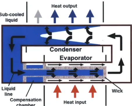
A schematic of the PHUMP design is shown in Figure 1-6 below. Heat is transferred into the base of the evaporator and conducts into a sintered wick, where it causes the working fluid to evaporate into a manifold of interconnected vapor channels. This wick is made of fine copper with a small pore size to provide the capillary pumping ability necessary to drive fluid through the loop and features high thermal conductivity to minimize thermal resistance. Vapor travels through these channels and into vertical transport lines that deliver it to the device's condensers. Here, vapor is cooled by the forced convection of the impellers and changes phase back to liquid.
Heat output Sub-ooled
liquid
+ + +
Condenser
Evaporator
|
Liquid line Wic'Compensation Heat input
chamber
Figure 1-5: The functionality of a Loop Heat Pipe is very similar to that of a traditional heat pipe, although the liquid and vapor transport lines are separated and a wick is used in the evaporator alone.
The condensers feature a sintered monel wick with a moderate pore size to evenly spread liquid across the condenser surface and to separate the liquid and vapor phases.
Liquid travels back to the evaporator, passing through the compensation chamber before returning to the fine copper wick and completing the cycle. The compensation chamber serves to
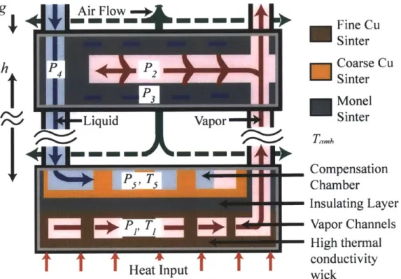
ensure the operational stability of the device, and is the focus of this work. It is made of a coarse copper sinter with a larger pore size than that of the evaporator base to allow for fluid transport with low viscous losses but good thermal spreading. In between these two components of the evaporator is a thin layer of Monel sinter known as the insulating layer to provide thermal separation. Monel sinter is also present in the condensers of PHUMP; this wick structure assists in the separation of the liquid and vapor phases present in the condenser to prevent failure of the device.
Fine Cu Sinter
4 P2 Coarse Cu
Sinter
Monel
Liquid Vapor Sinter
Compensation T .Chamber Insulating Layer Py T Vapor Channels High thermal conductivity
Heat Input wick
Figure 1-6: Schematic of PHUMP, including the evaporator and a single condenser. The Compensation Chamber is constructed
from
a coarse copper sinter, the Insulating Layerfrom
Monel sinter, and the High thermal conductivity wick uses afine copper sinter.The structure of PHUMP is made of Monel, with the exception of the copper evaporator base. This includes the evaporator frame, the vertical fluid connections, and the condenser frames. Monel is a nickel-copper alloy that features excellent corrosion resistance and chemical compatibility with water in heat pipes.
The PHUMP project was completed by a team of researchers at MIT. The condenser and evaporator design and construction were completed by Hanks [5] and Kariya [6], respectively, while the thermophyscial characterization of the sinter used in the device was performed by Dominguez [7]. The characterization of airflow in the device and impeller design was performed by Allison [8] and Staats [1], while the electric motor design was carried out by Jenicek [9].
1.4 The Need for a Compensation Chamber
Within the condenser of a heat pipe the liquid and vapor phases of the working fluid meet. At this interface, there is a pressure difference between the two phases that, if not controlled, can lead to reduced performance or the total failure of the heat pipe through one of two failure modes. The compensation chamber is installed to control this pressure difference and prevent these failures from occurring; it also extends the range of operating conditions and heat loads that the heat pipe can function in.
The stability of the liquid-vapor interface in the condenser is dependent upon the pressure difference between the two phases, the working fluid used, and the geometry of the sintered wick in the condensers. The pressure difference across the liquid-vapor interface in the condenser is governed by the Young-Laplace equation:
= 2acos . 1.3
r
Here AP is the pressure difference between the two phases, a is the surface tension, 0 is the contact angle between the liquid and the solid surface, and r is the radius of curvature of the
interface. When the vapor pressure exceeds the liquid pressure in the condenser, the liquid menisci between bulk gas space and the sinter liquid space will be concave; this configuration is
referred to as a receding meniscus. Similarly, when the liquid pressure exceeds the vapor pressure, the menisci will be convex and is referred to as an advancing meniscus. These two configurations are shown in Figure 1-7 below.
Experimental work has shown that the receding meniscus configuration is more stable than advancing, as it is capable of supporting a greater excess pressure before failing. For the Monel sinter used in PHUMP's condensers (particle size of 44 pim), a receding meniscus can support an excess pressure of 8 kPa, while an advancing meniscus can only support 1 kPa [5].
Pv Vapor Pv Vapor PL
>
V Advancing meniscus Receding rnexiiscusFigure 1-7: Advancing and receding menisci at the liquid-vapor interface in the condensers of
PHUMP. Receding menisci have been shown to be more stable than advancing, and is the
preferred configuration for stable operation. Figure taken from Hanks [5].
As such, a receding meniscus is preferred at all operating conditions. This requires the vapor pressure to exceed the liquid pressure in all condensers, and is accomplished using the compensation chamber.
1.4.1 Condenser Flooding
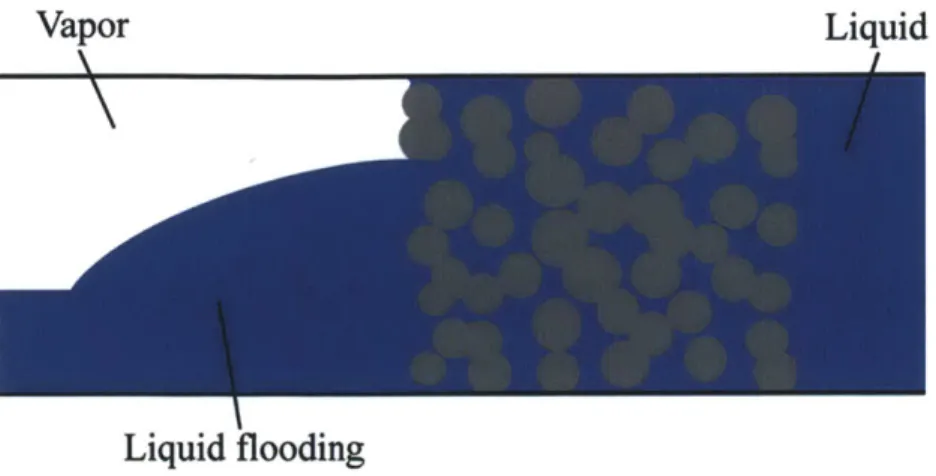
Condenser flooding in PHUMP occurs when the liquid pressure exceeds the vapor pressure in the condenser, and is depicted in Figure 1-8 below. This causes advancing menisci to form in the condenser. This configuration is unstable, as advancing menisci can only support a pressure difference of less than 1 kPa. Once this limit is exceeded, the capillary forces of the wick can no longer support the pressure difference between the two phases. Due to the geometry of PHUMP, a gravitational pressure head develops on the liquid side of the device. When upright, the liquid
Vapor Liquid
Liquid flooding
Figure 1-8: Flooding of the condenser occurs when the liquid pressure exceeds the vapor pressure by an amount greater than the wick structure can support. Without the presence of a
wicking structure, the transition to flooding occurs more abruptly. Figure taken
from
Hanks [5]. pressure in the lowest condenser exceeds that of the top condenser; the distance between these two condensers is 100 mm, leading to a gravitational pressure head (pgh ) of 1 kPa. If advancing menisci form in the upper condensers, the gravitational pressure head will cause the menisci to fail in the lower condensers.When an advancing meniscus fails, liquid floods into the vapor space of the condenser and reduces the surface area available for condensation in the device. As PHUMP features multiple condensers, this particular failure mode is not catastrophic but does lead to reduced performance as the thermal resistance of the device increases. Although advancing menisci are capable of supporting a small pressure difference, their unstable nature makes them poorly suited for PHUMP. As such, the liquid pressure must not exceed the vapor pressure in all condensers.
1.4.2 Evaporator Dry-Out
The second failure mode, evaporator dry-out, has more serious consequences than condenser flooding. Evaporator dry-out can occur when vapor enters the liquid lines of the device. This vapor can block liquid flow in these lines, preventing liquid from returning to the evaporator and
starving the evaporator of liquid. When this occurs, the heat transferred into the evaporator cannot evaporate any working fluid and instead causes the evaporator temperature to rise,
leading to an uncontrollable rise in the liquid and vapor pressures and temperatures in the device. This causes temperature of the evaporator base and thus the chip (or electronics component) that is being cooled to rise significantly, risking damage.
Evaporator dry-out can occur in two ways. First, if any liquid is near its saturation temperature in the liquid lines, it can flash boil into vapor. To mitigate this risk, the wick structure in the condenser forms a wide fin like structure known as the 'subcooling region' near the liquid lines. This region provides an area for sensible cooling of the working fluid to occur, reducing the temperature of liquid exiting the condenser to several degrees below saturation. If the vapor pressure exceeds the liquid pressure in the condenser, vapor will entrain itself in the liquid lines of the device.
If the vapor pressure significantly exceeds the liquid pressure in the condenser,
evaporator dry-out may also occur. When this occurs, vapor forces its way through the wicking structure in the condenser into the liquid line, as shown in Figure 1-9 below. The maximum pressure difference that the sintered wick can withstand, AP., is again given by the Young-Laplace equation:
A = -c 2P 1.4
a
Here, the radius of curvature of the liquid-vapor meniscus has been replaced by a , the pore size in the condenser wick; a is typically approximated as the particle size of the sinter used. In
PHUMP, APx is referred to as the 'capillary pressure' (P, ) of the condensers. The capillary
Vapor
Vapor Tendril Liquid
Flow
Vapor Sinter
Cavity
Figure 1-9: The beginnings of evaporator dry-out, as vapor forces its way through the condenser wick and entrains itself in the liquid line. Figure taken from Hanks [5].
experimentally measured using a process described in Hanks [5]; typical values fall in the range of 6-10 kPa.
Although the use of a wick structure in the condensers reduces the risk of these device failures, additional measures are needed if the device is to function effectively and in a stable configuration across a range of operating temperatures. To this end, the compensation chamber is integrated into the device to control the liquid-vapor pressure difference in the condensers. This is achieved by controlling the pressure on the liquid side of the device via a thermal control mechanism (the presence of a wick within the condensers allows for the independent control of liquid and vapor pressures). Within the compensation chamber, the working fluid is maintained at a state of saturation such that the temperature and pressure of the working fluid are coupled. This allows for control of the liquid pressure by setting the compensation chamber temperature. This temperature must be carefully maintained to avoid device failure; if the liquid pressure becomes too high, flooding will occur, while if it is too low evaporator dry out can take place.
1.4.3 Heat Pipes, Loop Heat Pipes, and Capillary Pumped Loops
While all loop heat pipes include a compensation chamber, there are differences in its implementation that serve to define two categories of heat pipe. When the compensation
chamber is integrated into the evaporator of the heat pipe, the device as a whole is referred to as a Loop Heat Pipe (LHP). However, when external to the evaporator, the compensation chamber is instead referred to as the liquid reservoir, while the device as a whole is known as a Capillary Pumped Loop (CPL). In this arrangement, liquid flows into and out of the reservoir only as the operating point changes, and not during steady state operation as in a compensation chamber.
The temperature control mechanism of this component also often differs amongst designs; as the temperature of this region is typically above ambient, heat input is required to maintain the working fluid at a state of saturation. This is typically accomplished through the use of some form of electric heaters in what is known as active temperature control. Active control is used for both CPLs and LHPs, and is the most common temperature control technique. However, it is also possible to control the temperature of the compensation chamber passively. Here, waste heat from the evaporator is used to maintain the saturation state within the compensation
chamber. This method is used only on LHPs, and is much less common as it requires careful design of the evaporator and compensation chamber. However, the lack of electric heaters reduces the energy requirements of the device, increasing its COP.
The Mk III PHUMP is an LHP that uses a passive compensation chamber for exactly this reason. Previous prototypes had featured both a compensation chamber and a liquid reservoir with electric heaters. These heaters required between 5 and 20 W of power to maintain the reservoir at the appropriate temperature, depending on operating conditions. This power
the maximum power consumption of the device of 33 W, the decision was made to remove the electric heaters and instead use a passive compensation chamber on the Mk III PHUMP. The design of this component is the focus of this work.
1.5 Prototype Development
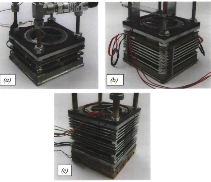
Three prototypes were developed during the PHUMP project. Each of these prototypes was designed to meet a set of performance targets. Following manufacture, extensive experimental testing was performed to characterize and understand the device's operation and measure key performance metrics (in particular thermal resistance and COP). These three prototypes are shown in Figure 1-10 below, and are discussed in greater detail in Chapter 3 of this work.
The Mk I prototype (Figure 1-10(a)) was designed to provide a proof of concept of the PHUMP design and better understand the basic operation of a loop heat pipe. This device
featured and a single condenser, and as such is termed the Single Condenser Prototype or SCP in Kariya [6]. The Mk II prototype (Figure 1-10(b)) allowed for the characterization of a multiple condenser loop heat pipe and was capable of dissipating greater heat loads than the Mk I prototype. The Mk II prototype utilized six condensers and is termed the Multiple Condenser Prototype or MCP in Kariya. The final prototype constructed, the Mk III (Figure 1-10(c)), was designed to meet or exceed the performance targets set forth by DARPA. The relative features and performance of these prototypes are summarized in Table 1-2 below; note that COP is not included as data on power consumption is not available for the Mk I and II prototypes.
Unlike the Mk I and II prototypes, the Mk III prototype did not include an external liquid reservoir in addition to its compensation chamber. As such, it could only function as an LHP, as opposed to the Mk I and II prototypes which could operate as both LHPs and CPLs. This work
Figure 1-10: The three prototypes developed for the PHUMP project, (a) the single condenser
Mk I prototype, (b) the six condenser Mk II prototype, and (c) the ten condenser Mk III
prototype.
Table 1-2: Performance and
features
of the three PHUMP prototypes. Mk I Mk II Mk IIIMaximum Heat Load 200 W 500 W 900 W
Minimum Thermal 0.1770C/W O.10*C/W 0.0630C/W
Resistance
Number of Condensers 1 6 10
Compensation Chamber Yes Yes Yes
details the design, manufacture, and testing of the compensation chamber used in the Mk III prototype.
1.6 Literature Review
Although LHPs and CPLs are widely used in a number of different industries, particular application requirements often necessitate application-specific designs. Nowhere is this more true than in the aerospace industry, which is responsible for the bulk of application based LHP and CPL literature produced. In this field, unique heat pipes are developed for each application, and mass production of a particular design is the exception. As such, there is not a significant body of work that describes the general designs of compensation chambers. Instead, when
designing a compensation chamber it is necessary to follow the unique guidelines and constraints set forth by the design of each device. This arrangement is not surprising when one considers the subordinate role that the compensation chamber typically plays in initial considerations of heat pipe design.
In spite of this, there are a set of general rules and best practices that become apparent when the relevant literature is considered. The vast majority of work in this field has focused on traditional evaporator designs that utilize a cylindrical form factor, while PHUMP's evaporator features a flat plate geometry that allows for a large heated area for use in a wide range of applications. Despite these differences, much of the work done by Ku [10], Schweickart et al.
[11], and Nikitkin et al [12] is nonetheless relevant to this work as it characterizes the behavior of LHPs and CPLs that remains constant regardless of design or geometry. Further general information on heat pipes is provided in the work of Reay and Kew [13] and Faghri [14].
1.7 Thesis Outline
The goal of this work is to detail the design and integration of a compensation chamber for use in a multiple condenser loop heat pipe. The resulting design was used in Chapter 1 described the motivation for this work, outlined some of the challenges present in this design process, and provided background information on compensation chamber design. Chapter 2 details the specific design requirements of the compensation chamber to be used in PHUMP, and the process and methods used arriving at the designs used in the PHUMP prototypes. Chapter 3 explains the experimental analysis used to evaluate the performance of the PHUMP prototypes and describes these results' implications on compensation chamber performance, as well as comparing the expected and actual performance of various compensation chamber designs. Finally, Chapter 4 provides conclusions for this work, evaluating the effectiveness of the designs used and indicating potential areas for improvement and future work, in addition to outlining some general guidelines for compensation chamber design.
Chapter 2: Design of the Compensation Chamber
This chapter details the development of the compensation chamber used in the 10-condenser PHUMP prototype. First, the thermal and mechanical performance requirements of the
compensation chamber are outlined. Initial designs are surveyed, and a form factor is selected. The analytical and computational methods used in the design process are described, and the performance of various designs is compared. A final design is selected, and computational predictions of its performance are given. Additional information is provided on the
manufacturing process used to fabricate this component.
2.1 Compensation Chamber Performance Requirements
The compensation chamber is a key component within a Loop Heat Pipe (LHP), and its design must be considered carefully if it is to perform its role effectively. Like many LHPs, PHUMP has certain design characteristics that place a set of unique design requirements on the compensation chamber. These thermal and mechanical requirements must be fully understood before
proceeding to the design phase.
2.1.1 Thermal Requirements
The primary role of the compensation chamber in PHUMP is to ensure that the device can operate over a wide range of operating conditions. In particular, this means that the device must avoid entering into any of the two failure modes described in Section 1.4. These two failure modes occur when the pressure difference at the liquid-vapor interface in the condensers falls outside of a range of stable values. The compensation chamber mitigates this risk by controlling the pressure on the liquid side of the device. As the compensation chamber achieves this control
thermally, the constraints on the compensation chamber pressure can be expressed as limits on its temperature. These limits are described below using a procedure adapted from that of
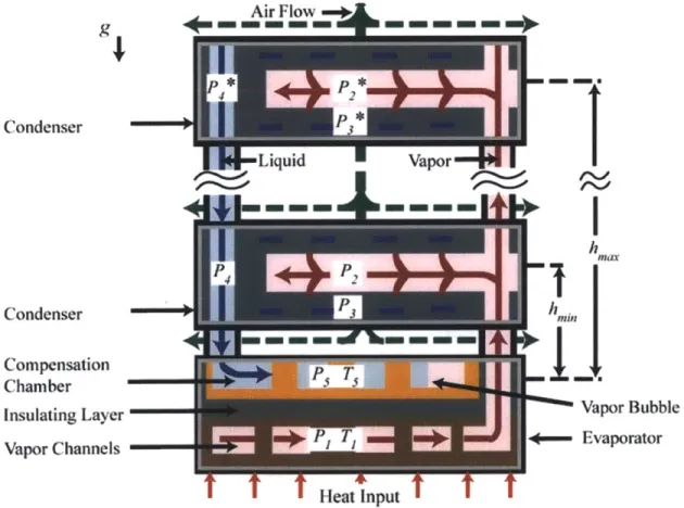
McCarthy [15] and Ku [10]. Figure 2-1 is provided to illustrate relevant locations throughout the device.
As PHUMP features multiple condensers oriented in a vertical stack, a significant liquid pressure head develops in the device as described in Section 1.4.1. When in its nominal (upright) orientation, the liquid pressure in the lowest condenser is approximately 1 kPa higher than the condenser furthest from the evaporator due to the 100 mm hydrostatic head (pgh.) between top and bottom condensers. In a traditional LHP, this would lead to flooding of the condensers.
Condenser Condenser Compensation Chamber Insulating Layer Vapor Channels h Vapor Bubble -- Evaporator I I I Heat Input I I I
Figure 2-1: Schematic of loop heat pipe operation showing evaporator, the uppermost and lowermost parallel condenser sections, compensation chamber, and liquid and vapor lines. Blue regions represent liquid flow, red and pink vapor, while airflow is shown with the green arrows.
The use of a wicking structure in the condensers of PHUMP reduces this risk, as it allows for control of the liquid pressure. To prevent flooding from occurring, the pressure of the liquid in the condenser wick must be less than the vapor pressure in the condenser. This places an upper bound on the compensation chamber temperature, or
P2 > P3 ,2.1
where P2 represents the vapor pressure in the lowermost condenser (at position 2) and P3 is the
liquid pressure in the lowermost condenser wick (at position 3). P3 can be related to the liquid pressure in the compensation chamber (P5) through the viscous losses that occur as the liquid
travels through the condenser wick (AP3'±1) and the liquid pressure head (pighmj) within the device (the viscous pressure drop in the open liquid spaces can be neglected). The liquid pressure is highest in the lowest condenser, so it will always flood first. As such, the distance between the compensation chamber and this lowest condenser, hmin, is used in all calculations of hydrostatic head, or
P3 = P5 - pighmin + AP'±. 2.2
Similarly, the vapor pressure in the condenser can be related to the pressure in the evaporator's vapor channels (P1) by accounting for the viscous losses that occur as the vapor travels through
the vapor manifold in the evaporator (A Pl'Y).
P2 = P1 - APr± . 2.3
Note that we have not included the vapor pressure head as it is negligible compared to other terms. Relations 2.2 and 2.3 can be combined to give the pressure difference between the compensation chamber and the evaporator.
This pressure difference, Pi - P5, is the pressure difference across the evaporator menisci and must be maintained as a positive quantity (corresponding to a receding meniscus) to avoid flooding of the evaporator vapor channels. As the fluid in both the vapor channels and the compensation chamber are at saturation states, the pressure difference between the two can be related to their temperature difference by sat' the local slope of the saturation curve.
P1 - Ps = (T1 - TO) sat.25
Substituting relation 2.5 into 2.4 and recognizing that Pi - PS must be greater than zero yields the thermal criteria for the compensation chamber that must be met if condenser flooding is to be avoided.
(dP2
.(T1 - T) > (AP3'± + AP11'2 - Pighmin)/ kdTJ - sat -a 2.6
Relation 2.6 prescribes the minimum temperature difference between the compensation chamber and the vapor channels. If it is less than this, the lowermost condenser in PHUMP will flood. To achieve this minimum temperature difference, sufficient thermal resistance between the vapor channels and the compensation chamber within the evaporator is needed. As will be seen later, this thermal resistance is dominated by the thickness of the insulating layer.
If the pressure difference across the liquid-vapor interface in the condensers becomes too large, vapor can burst from the vapor space through the condenser wick and into the liquid lines. This can cause evaporator dry out, as described in section 1.4.2. To avoid this, the pressure difference across the interface must not exceed the capillary pressure, Pcap, the maximum pressure difference that can be supported by the condenser wick, or
The uppermost condenser always experiences vapor burst through first as the liquid pressure here is lowest. As such, the distance between the compensation chamber and this uppermost condenser, hmax, is used calculating this burst through limit. The star notation in all superscripts (i.e. P2*) is used to differentiate pressures in this uppermost condenser from those in the
lowermost.
Requirement 2.7 can be rearranged to relate the pressure difference across the liquid-vapor interface in the top condenser to the temperature difference between the compensation chamber and the evaporator vapor channels.
PcaP > P1 - AP1 '2 - Ps - AP3' '4 + pig hmax 2.8
Pcap ~2.8
Pcap + AP1'Y2 + AP3'I4 - Pi9hmax > 7 1 - Ts) d)sat 2.9
Relation 2.9 places an upper bound on the temperature difference between the compensation chamber and the vapor channels. If (T1 - T5) exceeds this value, vapor will begin to burst
through the wick in the uppermost condenser and evaporator dry out may occur. This limits the thermal resistance between the vapor channels and the compensation chamber; if it is too low, this maximum temperature difference will be exceeded.
The two thermal constraints presented in relations 2.6 and 2.9 establish bounds on the temperature of the compensation chamber relative to the evaporator. To meet these criteria, the thermal resistances between the vapor channels, the compensation chamber, and the ambient temperature above the evaporator must be carefully selected. The design of this thermal circuit is the primary focus of the remainder of this chapter.
Table 2-1 below includes typical values for many of the parameters used in the above equations for operation at a fan speed of 6000 RPM and a heat load of 1125 W. The viscous loss
Table 2-1: Values ofparameters used in calculation of operating limits. Quantity Value P1 34.6 kPa AT'is 1.83 kPa AP'is 2.25 kPa p1ghmax 1.0 kPa p1ghmin 0.2 kPa Pcap 8.0 kPa Tambient 22.5 *C T1 72.5 0C
(dP
1.47 dsat octhrough the condenser wick and the condenser capillary pressure, APf'±i and Pcap, respectively, were determined experimentally using methods described in Hanks [5]. The viscous losses in the evaporator's vapor channels, APliS2, were calculated computationally using COMSOL
Multiphysics simulations described in Kariya [6]. The hydrostatic pressure heads, pighmin and p1ghmax, are a result of the geometry of the device and reflect values of hmin and hmax of 20
mm and 100 mm, respectively. The vapor temperature at this operating point, T1, is provided by
an air flow model from Staats [1] used to predict the performance of PHUMP prototypes and described later in this work. The associated saturation pressure, P1, and the slope of the
saturation curve, -P) evaluated at T1, the vapor temperature, are taken from established
(_Tsat
property data tables [16].
2.1.2 Mechanical Requirements
The thermal requirements outlined above define the thermal design requirements of the
compensation chamber in PHUMP to stabilize the liquid-vapor interfaces within the condensers of the device. The compensation chamber must also accommodate the volumetric expansion and
contraction that occurs as the device operates over a range of environmental conditions. As the fluid's density changes with temperature, the total volume occupied by the liquid phase varies as the operating temperature changes. The compensation chamber must be sized appropriately to accommodate this volumetric expansion. The volume of the liquid channels in the compensation chamber also changes due to thermal expansion of the copper sinter over this temperature range. Due to the small coefficient of thermal expansion of Monel relative to water, this change is very small over the temperature range experienced by PHUMP and is neglected (Monel has a thermal expansion coefficient of 2* 10 OC [17]; its expansion is more than three orders of magnitude less than water over this same temperature range).
A procedure for sizing a compensation chamber is provided in explicit detail by Ku [10]. Its most basic requirement is that the volume of the expansion chamber be larger than the total possible range of volume change of the liquid under all operating conditions, or:
Vcc > mi,max(vl,hot - vi,cold) 2.10
Where, V1,hot is the specific volume of the liquid at the maximum operating temperature of the
device, V1,cold the minimum operating temperature of the device, and Vcc the compensation
chamber volume. mi,max is the liquid mass in the device at the maximum fill ratio; this fill ratio is used to determine the lower bound on the compensation chamber volume as here the
volumetric swing will be the greatest.
The compensation chamber included on the first two prototypes featured a total volume of 5.6 mL. This proved sufficient for operation between 200C and 750C. However, as the final prototype featured additional condensers and working fluid, more volume was needed.
Modifications to the compensation chamber design were required to expand the capacity of the component by 1 mL, a process discussed in greater detail in section 2.5.
2.2 Design Overview
As LHPs and CPLs are often designed for particular applications, many of the components within the device are designed to meet a unique set of requirements. As such, no single compensation chamber or liquid reservoir design predominates, with the application and
operating profile dictating the unique requirements that the designer must follow. This is true of PHUMP, where the compensation chamber design was heavily influenced by manufacturing and geometric constraints in addition to those mentioned above.
A cross section of the evaporator used in previous prototypes is shown in Figure 2-2 and depicts the various wicking layers used in the device. This initial design placed the compensation chamber at the top of the evaporator, separated from the vapor channels by a 4 mm thick layer of Monel sinter known as the insulating layer. The first two prototypes featured a liquid reservoir external to the evaporator in addition to this compensation chamber, allowing the device to function as both an LHP and a CPL. However, although LHP functionality was observed, a redesign of the compensation chamber was necessary to achieve the high performance required.
Liquid Air Flow
Compensation
ChamberVapor Bubble
Chamnber
Insulating Layer Vapor
Vapor Channels Evaporator
Heat Input
Fine Cu Coarse Cu Monel
Sinter Sinter Sinter
![Figure 1-]: Ranges of heat fluxes that can be cooled by various physical phenomena](https://thumb-eu.123doks.com/thumbv2/123doknet/14732263.573269/14.918.146.745.112.353/figure-ranges-heat-fluxes-cooled-various-physical-phenomena.webp)