Aji
The Development and Characteristics of Fans
Albert Edward Southam Isidor Loss
II. Pan Testing
III. Drives for Fans
IV.
The Design
of
Fans
V. The Development of Centrifugal Fans
VI.
Results of Tests using Various Shaped Inlets
VII.
Summary of Current Literature on "The Development
and Characteristics
of
Centrifugal Fans"
(a)
"Forced and Induced Draft with
Mechan
ical Stokers"
(b) "Some Developments in Fan Design"
(e)
"Pitot Tubes for Gas Measurement"
(d)
"The Designing and Testing
of
Centrifugal Fans"
(e)
"Latest Developments
in Fan
Design"
(f)
Bibliography
1
I. Uses of Fans
Fans and blowers are used for many purposes the most important of which are as follows: (1) Power Plant Work - The fans here are used for furnishing the forced draught thru the fuel bed and to furnish the induced draft in case where econ-omizers are used or where conditions are such that to furnish the required draft too tall a stack would be necessary. If a stack has been designed for a definite boiler rating any in-creased rating of the boilers will require additional draft. There is no practicable means of increasing natural draft as such after the maximum has been reached, Again chimney draft is susceptible to a large extent to natural atmospheric condi-tions, winds and air currents. So that for many power plant installations artificial draft is a necessity. It is very flex-ible and can be readily adjusted to meet various rates of com-bustion, it does not depend on climatic and atmospheric condi-tions and permits any degree of overload without decreasing the effeciency unduly. (2) Heat, Ventilating, and Air.Conditioning Processes- In many large buildings, factories, auditoriums etc.
it is necessary to keep contents of the rooms withim certain limits. This is accomplished by sending air thru the buildings
by means of fans. This air may be sent over heating stacks
and in this way heat the buildings. The value of a proper ven-tilating system can be seen from the following report of Prof.
S.H. Woodbridge of Boston which says: death rates have been
reduced by the introduction of effecient ventilating systems in children's hospitals from 50% to 5%. To accomplish
haust air from the building or force air into it or by a combina-tion of the two. In any case the fan is used as being the source of the most efficient aeromotive force. (3) General Engineering
Processes-- Included under this there are fans and blowers used for sending air to blast furnaces, fans for properly ventilating mines and many other minor uses.
II. Testing of Fans
In the test of a fan the quanities to be determined and the general characteristics sought should depend upon the uses to which'the'fan is to be put. If the operating conditions of the fan are such that its speed is to remain sensibly constant
this should be the independent variable. Or the speed of the fan may be varied and the pressure and velocity of the air
changed. The air velocity and pressure may be varied for a given speed only by changing the size of the air discharge pipe.
A useful set of tests may be had by keeping the speed of the fan practically constant and varying the pressure. Or the fan may be operated at a variable speed and.the pressure kept constant
by adjusting the external resistence to the air. This may be
done by using different nozzles or orifices as outlets from the discharge pipe. A convenient arrangement for doing this
is to have an arrangement at the end of a pipe whereby the open-ing may be changed. This can be done by making a holder at
the end of the pipe and making arrangements for inserting plates with different sized openings into this holder. The duration
of a rum should be aboutteniiminutes and several sets of ings made during the time and their average used, as the read-ings for the run. The following measurements are usually made.
(1) Measurement of Air Volume
By this is meant the amount of air in cubic feet per minute flowing thru the discharge duct or pipe, and it may be measured with a good degree of accuracy. There are two general methods in use for obtaining this quantity, the pitot tube and
the anemometer methods. The anemometer consists of a light, delicately constructed fan wheel whose motion is transmitted to a system of practically frictionless gearing within an attached case. The movement of the fanwheel is registered on a dial by hands revolving upon graduated circles and the velocity of the air in feet per minute is thus indicated. Such an instrument
0
if well calibrated will give good results. In using the
ane-wheel
mometer the fan wei is held perpendicular to the direction of the flow of the air and the instrument is moved slowly. The time is noted and the readings of the dials divided by the time in minutes will give the velocity of the air. The velocity thus obtained corrected for any known error of the instrument multiplied by the area of the passage will give the volume of air passing. It is necessary to correct all readings by means
of a factor determined for the particular instrument used. As no two anemometers are alike this correction will be different for each instrument and it therefore is a necessity. The ane-mometer should not be used where great accuracy is required.
A second method of measuring the quantity of air is
by use of the Taylor Pitot Tube. This consists of two tubes
moving and are turned parellel to the direction of flow so that the moving air impinges on the end of the tube. The two tubes are connected to U tubes containing a column of water. The inner
tube having the open end receives the full force of the air and registers both pressure and velocity head or the dynamic head so called. The end of the outer tube is closed and slits are provided on the side of the tube so that only the static head is registered. If now the inner tube is connected to one end of a differential gauge while the other is connected to the other arm the head registered by the gauge will be the difference between the total or dynamic head and the static head; and is
therefore the velocity head. Having obtained the velocity head the following relation holds:
V is the velocity in feet per second.
G is the acceleration due to gravity or approximately 32.2. H is the velocity head in feet of air.
But PV = WRT
pV 4.4 2-7 FOO07
If the value of H as read by the gauge is in inches of water the following transformation is made:
V
X
Q--2)a-p
0,
-V is the velocity of air in feet per second, 5
H is the velocity head as read by the differential gauge in inches of water.
T is the absolute room temperature and is equal to the room temperature in degrees Fahrenheit plus 459.5.
P is the absolute pressure of the air in the pipe in pounds per square inch.
Knowing the velocity of the air the pipe we multiply it by the cross sectional area of the pipe in the proper units and obtain the quantity of air flowing thru the pipe per minute. Various
differential gauges are used for measuring the velocity head. The "Ounce Gauge" made by the Sturtesant Company will measure
large differences in pressure up to twenty ounces of water pressure The Ellison differential draft gauge is also used. For the
de-termination of very small differences in pressure a device known as a hook gauge is used. This is a form of U tube but the level of the water is accurately determined by the aid of a hook gauge. With this instrument the readings of differences of one
one-hundreth of an inch of fater is a simple matter.
In using the Taylor pitot tube for accurate work the cross section of the pipe or duct should be divided up into equal con-centric areas and readings for velocity obtained for each area and then the mean of these readings obtained should be used for determining the air velocity. If the work does not have to be very accurate the tube may be held in the center of the air duct and a single reading made. Experiments have shown that a good value for the pipe factor is .828 i.e. if a reading is made at
7
the center of a circular pipe, this reading multiplied by .828
is a good value to use for the mean velocity in the pipe. If this coefficient is used and the air is assumed at standard con-ditions that is 14.7 lbs. per square inch and 700 F the expression
for the velocity is:
V =4
-V is the velocity in feet per minute.
H is the velocity head in inches of water.
8
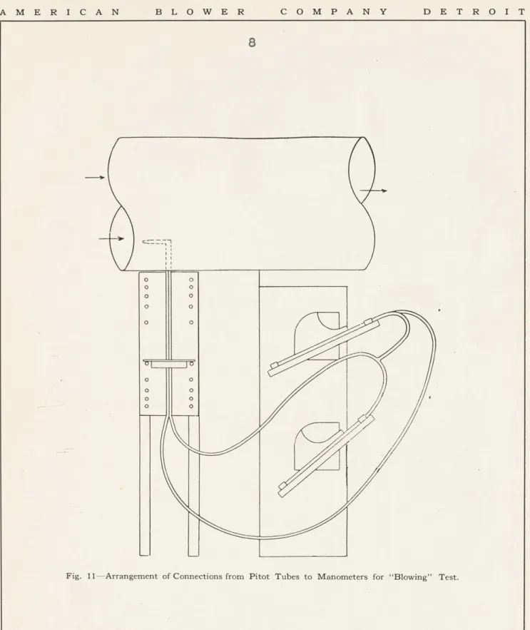
Fig. 11-Arrangement of Connections from Pitot Tubes to Manometers for "Blowing" Test.
21 o o o 0 o 0 o o o 0 o 0 o o o 0 o o
T H E P I T 0 T TUBE AND F A N T E S T I N G I
j
0 0 0 -- 0- 0 0 0Li
0_
_/1
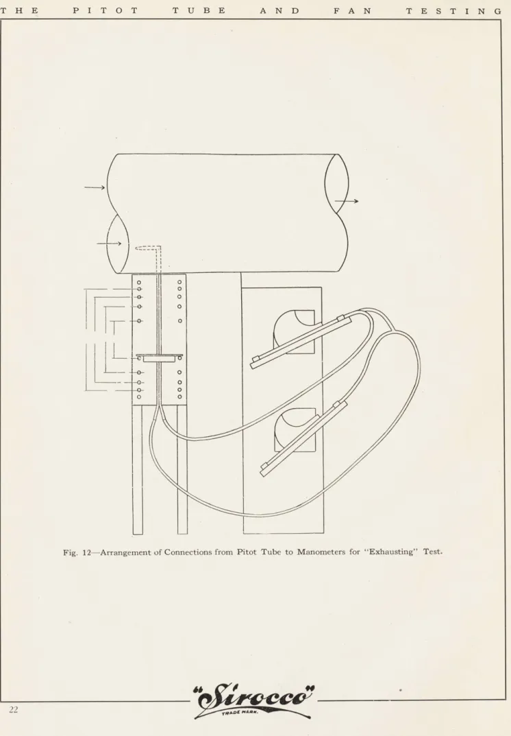
Fig. 12-Arrangement of Connections from Pitot Tube to Manometers for "Exhausting" Test.
22
9
46.
I)
-J P/.O UBE PEC i, It I I/T T I ~ I \ ' N -32//i ILS P/TOT TUBE A TEST PIPE(--t09 8 7 6 HORIZONTA4L POSIT/ON 5 4 3 r I P/TOT TUVBE 8o~qRD IonH
Fig. 13-Method of Adjusting Pitot Tube.
rAMARK. 23
1 11 k L'%L
T -2 T TT
-A
T H E P I T 0 T TUBE AND F A N T E S T I N G
velocity and high static pressure results. If the end of the test pipe is partially closed, the effect, as regards the resistance against which the fan must operate, is the same as attaching the fan to a system of ducts. In blowing tests the outlet of the test pipe is restricted and for exhausting tests the inlet is restricted. Thin flat plates with round orifices are used for restricting the area of the test pipes and it is usually ample to test a fan with the pipe full 34, 8, 2, 38, and 4 open and entirely closed off. The area of the opening di-vided by the area of the test pipe is the ratio of opening or equiv-alent orifice. The power required for driving a fan in determined
by means of one of the usual forms of dynamometers or by the power
input of an electric motor which drives the fan. Calculations
The relations between fan speed, pressure, volume delivered and power required have been fully verified by tests and under the same conditions of air density and with the same fan are as follows:
a. The volume of air discharged by a fan varies directly as the number of revolutions, that is:
velocity volume revolutions
Velocity Volume Revolutions
b. The pressures produced vary as the square of the revolutions,
static total revolutions2
Static Total Revolutions 2
c. The power required to drive the fan varies as the cube of the revolutions,
power revolu tions
Power Revolutions
In making fan tests the speed may not be constant at all times for a particular test and the above relations are used for making corrections for a common speed.
It is important to have a standard weight of air at which fan performances may be compared. The density, while ordinarily a small factor, affects the results considerably if extremes are great, as with heated or cold air and air at high altitudes.
24
(2) Measurement of Horse Power Input
The determination of the horse power supplied to the fan will depend of course on the method by which the fan is driven. If the fan is motor driven the input to the motor must be deter-mined and then subtracting from this input the motor losses the
input to fan can be determined. Usually the unit as a whole is tested and then the input to the unit is the input to the motor. If the fan is steam driven the energy removed from the steam mul-tiplied by the mechanical effeciency of the engine at that load is the input to the fan, and as before if the unit as a whole is tested the input to the unit is the input to the steam engine or turbine. The same method is used when the fan is driven by a gas engine. If the fan is belt driven a transmission dynamometer
can be used to advantage. Allowance should be made for belt losses as the power supplied to the fan shaft is desired. This may be done by using the revolutions per minute of the fan shaft with
the torque shown by the dynamometer to calculate horse power and multiplying the result by the ratio of diameters of fan pully to dynamometer pully. This will allow for the belt slip. A useful
quantity used in. the testing of a fan is the gross air horse power. Gross Air Horse Power W (H
33000
W is the pounds of air delivered per minute.
H is the total head as determined by the gauge in feet of air.
The speed of the fan is noted by a counter or by means of a Hassler Tachometer. The mechanical-effeiency of a fan is the air horse
1
power supplied. Another useful quantity by which fans can be
judged is the horse power supplied per thousand cubic feet of free air per minute. This expression is analogous to the duty of a pump. An expression frequently mentioned in the performance of fans is
the manometric effeciency, this effeciency being the ratio of the dynamic head as actually observed to the maximum theoratical
dynamic head. The theoratical maximum dynamic head being the dynamic head of the air at the tips of the blades.
The volumetric effeciency of a fan is the ratio of the actual volume of air passing in a given time divided by the im-peller displacement for the same period. The expression for this
is as follows:
volumetric =Volume discharged in cubic feet per minute Impeller displacement in cubic feet per min.
Tr i1) "-A/3
Q
is the volume discharged in cubic feet per minute.D is the diameter of the impeller in feet.
N is the revolutions per minute of the wheel. B is width of the impeller in feet.
General Relations between the quantities is rather interesting. The horse power required to operate a fan will vary directly as the work the fan does and inversly as the effeciency of the unit that is:
Horse Power
=
K QxPato drive fan E
Where K is a constant
Q
is the volume of air handled. a is the dynamic pressure.E is the total effeciency of the unit.
But the velocity varies as the square root of the head that is:
V
and
Q
1 AVtherefore K
where P is the dynamic pressure of the air.
Therefore substituting in the expression for horse power for the value of
Q,
we obtain:Horse Power
=
Kpi to drive fanThis shows that the horse power required to drive a fan varies as the three halves power of the dynamic pressure of the air.
Since the capacity of a fan is directly proportional to the periph-eral velocity or fan speed and the pressure developed varies
directly as the square of the speed' it follows that the horse
power required to drive a fan varies as the cube of the speed that is:
rr
but H P (N
or HPI ~= MN
H.P. is the horse power required to drive the fan. M is a constant for a given fan.
13
Hence it is important to note that even for a moderate in-crease in speed the horsepower to drive goes up very fast, Hence in selecting a fan either the right size should be chosen or a larger size. It is as a rule more economical to err in select-ing too large a fan than one which must be forced above its rated speed. Also as the capacity varies directly with the speed the horse power will vary directly as the capacity and consequently the remarks in regards to speed regulation apply here also.
Several approximate rules which are useful in power plant work in connection with fans are as follows:
Rule (1) the cubic feet of air to be supplied per minute by
a forced draft apparatus is equal to four times the number of pounds of coal burned per hour.
Rule (2) the cubic feet of gases handled per minute by the induced draft apparatus when no economizer is used is equal to eight times the number of pounds of coal burned per hour.
The above are practical rules determined as a result of tests
by A.A. Potter, dean of Engineering at the Kansas State
Agricul-tural College and S.L. Simmering, an instructor at the same institution.
The Influence of Air Temperature on the Performance of Fans In quoting the output or capacity of a fan or blower the temperature of the air handled should be noted as the volume per unit weight of the air changes with the temperature. A fan
chosen to handle air at say 600 F will not give the same perform-ance when handling flue gas of a temperature of 500 or more
degrees Fahrenheit.
The expression for velocity of air previously derived shows that the velocity is proportional is to the square root of the dynamic pressure and inversly proportional to the square root of the density that is:
Hence it is evident that the greater the density the less the velocity and the less the density the greater the velocity. The density of air varies directly with the temperature, the higher
the temperature the less the density. Hence for the same value of dynamic pressure air at a high temperature will have a greater velocity of flow than air at a lower temperature,
15
Relation Between Actual Pressure to Maintain a Given Velocit of Air and the Theoratical
Value
If there were no friction or pipe constructions the quantity of air flowing thru a given section of pipe would be determined by multiplying the velocity by the area of the section. Usually however there is a friction loss depending on the shape of the section thru which the air is flowing, and the expression for the quantity has to be multiplied by a coefficient depending
on the shape of the section. What value to use for C depends upon the judgement and experience of the engineer. Approximate values for the coefficient are as follows:
square tube C
=
.82round tube C - .85
rectangular tube C
=
.80Blast Areas of Fans
Up till now in the discussion of fans nothing has been mentioned as to the size or area of the outlet orifice although
it has been assumed that it was large enough to allow the air to pass out. If the outlet orifice is small the air will pass out of
it with the velocity of the tips of the blades. If the opening is increased this same condition will hold until the opening is of such size beyond which the velocity of the air is less than that of the tips of the blades. Hence the blast area of a fan may be defined as that theoratical area of outlet which will allow the maximum quantity of air to pass out while the pressure in the fan
housing remains equal to that corresponding to the velocity of the tips of the floats. By theoratical is meant one whose coefficient as presiously discussed is one. Hence if the R.P.M. of a fan is known and its capacity the blast area can be calculated from the following:
S=A V = r'D N A
TD N
In ordinary heating and ventilating work the blast area is a matter of small importance but in exhauster work for mills and factories where it is necessary to choose a fan to carry away shavings, lint, etc. and where the velocity of the air in the ducts must be quite large, the blast area is of importance and determines the size of fan to use. In many fan catalogues the blast areas of fans are given. If in practice the di-scharge opening of the fan is to be
17
less than the blast area the quantity of air which will be handled
can be determined as follows:
Where Q,is the discharge.
D is the diameter of the fan
N is the revolutions per minute of the fan
A is the outlet area
C is a constant depending upon the size, shape and length of the outlet,
If the discharge area is greater than the blast area the quantity of air which can be handled cannot be definitely known and experi-ments are the only means for determining the value.
Typical Test on a Fan as performed in M,E, laboratory of M.I.T.
Object: To determine the working characteristics of a Fan. Apparatus:
A D.C. Shunt Motor was used to drive a 24" Fan, Sirocco
Type, supplying air to a 19 inch pipe. The back pressure in the pipe was varied by changing the size of the outlet at the end of
the pipe. The dynamic pressure and velocity pressure were measured
by means of a Pitot inserted as shown in figure on the following
page. Due to friction near the surface of the pipe the velocity there will be less than at the center. To obtain the average
velocity pressure it is necessary to read the Pitot tube for several sections as shown in figure on next page. The cross section of
the pipe is divided into five concentric rings, and readings are taken at the intersection of the mean circumference of the rings and the diameter of pipe, and also at the center of the pipe, making eleven readings in all, the average of which is assumed to
be the true value for thevelocity. The Pitot Tube does not read velocity directly but reads the velocity head. To get the velocity
the formula
H is the velocity head in feet of the fluid.
This formula is not convenient, and one is desired in which H can be expressed in inches of water.
By dividing the average velocity by the velocity at the center a value known as the pipe factor may be obtained. If con-ditions are then allowed to remain unchanged it will not be necessay to take eleven readings of the Pitot Tube for each run, but merely
19
the velocity at the center to obtain the average value in the pipe. The output is calculated by multiplying the average
velocity in feet per second by the area of the pipe. The input to the fan must be measured indirectly from the output of the motor, which will be given by:
Input - Losses
El -f -RO -V T
S-raj-ower-A,-ri
I-2-30"/f'lea
Data:
Barometer (30.17")
Room Temperature Diameter of Pipe
Field Currenlt of Motor Armature Resistance 14.8 Sq. in. 730
F
A 1.
97 Sq, t*FT 0.80 amp. 0.48 ohm. Stray Power 700 710 720 730 740 750 r.p.m. 413 watts 422 431 441 451 461 Location of Pitot velocity. Zone 1 2 3 4 5 Center Size of openingTube from pipe wall to give mean zone
0.0256 0.0817 0.1460 0.2260 0.3420 0.5000 D D D D D D DP VP SP VP Volts Amps 1 2 100% 3 A= 1.97 4 sq. ft. 5 Center 6 7 8 9 10
IOO
Average
75% sq. 50% 25% 0 A= 1.40 ft. avg. A=1.08 A= 54 A= 0 1.23 1.32 1.35 1.32 1.31 1.23 1.24 1.24 1.26 1.21 1.01 1~.24 1. 1. 1. 2. .98 1.09 1.09 1.06 1.08 1.07 1.08 1.08 1.05 .98 .72 .99 .45 .26 .093 0 64 77 92 29 .99 1.045 1.045 1.03 1.04 1.035 1.04 1.04 1.025 .99 .848 .25 1.012 1.19 1.51 1.83 2.29 . 69 .54 .31 0 230 22.55 228 230 230 230 16.00 13.50 10.75 10.25 Zone RPM 720 730 740 746 75421
Results:
'
100%
Density of Air in Room' 075
" " " Pipe' 075
Ave. Velocity Air Pipe' 67.6
Velocity at each zonell 66.2
2' 69.9 3' 69.9 4' 68.8 5' 69.5 6' 69.5 7' 69.5 81 68.5 91 66.2 101 56.6 01 69.2 Velocity at Center (ft.)(sec.) Pipe Factor
Velocity at Tips of FaA Blades ft./sec. '
Capacity (cu. ft.)(min) Input to Fan(Horsepowef') Air Horsepower ' Mechanical Efficiency%' 9 9 69.2 .978 75.5 7992 5.80 1.56 26.9 Percent Opening t I I I 75% 50% 46.1 36.1 5448 3.90 1.41 36.0 4266 3.20 1.19 37.1 25% 20.7 2448 2.40 .74 30.9 0 0 0 1.83 0 0
Calculations:
(1) . Density of Air in Room PV= R.T. Y= 53.35 (533)-14e8xn44
density
1,...
-13.32 13.32 ou ft. per lb. - .075(2) Density of Air in Pipe
53,.35(3 1 44xS. P. O •m 12 6 hsp (0362) #/sq." 144 -- 25 (0362) -53.-35 (533) 144 x 14.83 - 13.32 v _ 53,35 (533)-144 (14.86) V- 13.28 V= 53, 35 ( 533) 144 (14.87) V- 13.28 V= 5335 1(33 V- 13.25 Vm 53,35 (533) 144 (14.9) v= 13.24 S.P... 1.19 (0362) .043 14.82 density . .0753 S.P, 1. 51. (0362)-density = .0753 S.P.- 1.86 (0362) -density = .0546 .0672 .0754 S.P-m 2.29 (0362) -density -.083 .0755
Consider density equals .075 for all runs, error very slight.
100% .0091
density = .075
71%
54.8%
Calculations:
(3) Average velocity of air in pipe
66.8 x 66.8 x 66.8 x 66.8 x 1.012 .69 .54 .31 - 67.6 ft./sec. = 46.1 = 36.1
=
20.7(4) Velocity in each zone (for 100% opening only.)
66.8 x 66.8 x 66.8 x 66.8 x 66.8 x 66.8 x 66.8 x 66.8 x 66.8 x 66.8 x .99 1.045 1.045 1.03 1.04 1.04 1.04 1.025 .99 .848 66.2 69.9 69.9 68.8 69.5 69.5 69.5 68.5 66.2 56.6 1/sec.
(5) Velocity at Center (for 100% opening only.)
c = 66.8 x 1.035
=
69.2(6) Pipe factor (for 100% opening only.)
vel. ave.- .978 P.F.
=
vel. center - 69.2 = 10o%= 71%= 55%- 7%=-0 =-0 1=
2= 3= 4= 5= 6= 7-8=
9= 10=
=
=
"Calculations:
(7) Velocity of tips of fan blades (100% run) 24" diameter
IT 2 720
60 - 75.5 ft/sec,
(8) Capacity of Fan
100% run 1.97 x 67.6 133.2 cu. ft/sec. 7992 cu ft. min
1.97 x 46.1 1.97 x 36.1 1.97 x 20.7 1.97 x 0
=
90.8=
71.1=
40.8 = 0 (9) Horsepower Input HP = 100% run 75% run50% run
25% run HP. HP. HP, HP. E I - Ra Ia
2 - V If - Stray Power 746 (230 x 22.5) - .48(21.75) 2- 230 x 8 - 431 5.80 (228 x 16) - .48 (15.2) - 228(,8) - 441 746 3.90 2 230 (13.5) - .48 (12.7) - 230 (.8) - 451 746 3.20 2 (230 x 10.75) - .48 (10) - (230 x .8) - 457 -746 2.40 DN 60 ft./sea. 75% .0% 25% 5448=
4266=
248825 0 HP* - (230 x 0.25L --- 61.8348(95 2.. (230 x 8) - 465 1 746 (11) Air Horsepower HP• Q x 5.2 x Dyn. Press. 550 100% HP. 75% 50% 25% 133,2 x 5.2 x 1.24 550 90.8 x 5.2 x 1.64 550 71.1 x 5.2 x 1.77 550 40.8 x 5,2 x 1.92 550 ~
1.56
1.41 -1.19
- 741 0 0 (12) Mechanical Effficiency 100% 50% 25% 5.80 3.90 320 .741 2. 400 output = Input -- 26.9%=
36.0% 37.1% = 30.9% 0 0tf-H-~-FiTh±H*H-H-t H--L '4 -11 --L :T!ii
01 -.40. I'7 70 AvARD CCOPERATivE SOCiETY, CAMBR :CG-T TECHNOLOGY BRANCHL B
*
6
1--Q I ! , r-7-771- ., . wm l .. ,; I T 4i II
i I i I I I I I J I ii !I-i !I-i -! i ! ! i t iF; F17-1, -FIFFI 4 -t ,-27 ±7 411 '~IH- F-U 0 *7 0 .4 0 a 0 4% 0 I. 4~Q) e,~o 0) U', zt~o rq*I'. H-H -H-TT Aft-H-T I-T + I- +-4-± U-I~h +F--1 ~ ~ -H -H+H-k -r 4-H -i-v I -~ ICE 'F - -F -I-il-k-I-i K:I, fi-H iFlF,4-i i in4T F1;111 Tnl FTWTvm'
-1-0 TEC' "LOGY BRANCH
HARVARD OSOFT-ATA'E SOETY, CAIMDRI19
-H+-p 2-o ! I 1 1 1 i 1 1 ; I i ! ! ! I- Z 1 ; ! i 1 -+-4-I -+-4-I I I I LLI Rlf ) . I I
i
. I I . I I I LLL E11-I 1 ) i t i Fm; i I !i 174. -T -T S-L .00" VE4 it I 1 4+ +4-it i i i i i LFI I-I I I I I I I I tA =. 4L k 1 -0 I H-1 1-7, I d.Adiiii
After a test has been made on a Fan the performance
and characteristics of a Fan can best be judged by plotting the values obtained, Various methods are used for this purpose. One is to plot the volume in cubic feet per minute as abscissae and
the velocity pressure, static pressure, horsepower input, and mech-anical effeciency as ordinates. The ratio of the static to the dynamic pressure is also frequently plotted. For a given type of Fan, if a Fan is tested handling air at a standard density, and
the diameter of the Fan wheel is one foot comparisons can easily be made. The Fan should be run at such a speed as to produce a
pressure of one inch of eater due to the velocity of the blades, this being at 1274 revolutions per minute. Then from the curves the performance at any other speed can be computed by noting that
the volume varies as the first power of the speed, the pressures as the second power, and horsepower to drive as the third power. The effeciency remaining constant for any given load points of the curve. It should also be noted that the capacity of a given design of Fan operating against a given static pressure at a
given speed varies as the square of the diameter. From the above simple rules Fans of symmetrical design can be judged from a
curve such as mentioned. Frequently the ratio of effect or full opening is plotted as an ordinate, This gives a means of judging
the characteristics of a fan against various sized openings. If this data is plotted and the use to which a fan is to be put is
known the effective opening can be closely arrived at and the opera-tion of the Fan noted. Just what the effective opening of a Fan will be in operation (actual) cannot be definitely determined
29
but the
judgement
and experience of the engineer will ledd him to choose a proper value.Three general methods for driving Fans are used, by motor, steam engine and steam turbine. Which method should be
used is governed by the-existing conditions. Motors are quite dependable when a reliable source of power can be secured either from the generators of the power plant or from some public service
company nearby.
Whenever it is desired to have the fan independent of external sources of supply steam should be used, either a steam engine or steam turbine. When starting the plant steam may be
generated in one of the boilers by natural draft, and sent to the fan. As the fan starts the draft through the fire bed increases generating steam more rapidly in the boiler and increasing the pressure. As the pressure increases the fan will operate more efficiently and the steam boilers will soon be generating the steam required for the plant.
Whether a steam turbine or a steam engine should be used depends upon the speed and output desired. Steam turbines operate most efficiently from at 2000-3000 r.p.m. and at such a speed
volumes as high as 194,000 CFM may be handled according to data from a catalogue of B.F. Sturtevant-Co. Hyde Park, Boston, Mass. When still larger outputs are desired the size of the fan must
be increased, and as the maximum speed is controlled by the
strength of the fan blades the speed must decrease that the fiber stress at the tips of the blades shall not exceed a proper work-ing value. To reduce the speed to lower values, say 100 R.P.M. reduction gears must be used with the turbine or the turbine be
31
replaced by a reciprocating engine, In general a steam turbine will be used to blow relatively small quantities of air against a
high static pressure, and a reciprocating engine will be used when it is necessary to handle large quantities of air but against a small static head. Turbine blowers will be used for forced draft and engine driven fans for induced draft.
Fans are often belt driven, allowing slow speed engines to be used to drive high speed fans. In places where there was a large cheap supply of gas, such as about steel works, the fans might be driven by gas engines. As the head against which the fan must work would be larger a high speed fan would be required.
Gas engines run at a rather low speed, and a belt drive would be needed. One disadvantage of such a drive is that the fan must be
started before any gas would be available for driving it, requiring either the use of a secondary gas supply, such as illuminating
gas or a separate auxiliary method of driving.
Steam driven fans are preferable to motor driven fans for high pressure steam from the boiler,s may be used to supply
the energy, and the exhaust steam may be used for heating purposes.
(IV)
The Design of FansUnder this heading we will discuss the general features of the design, while later under.the performances of fans we will mention the relation of design to performance.
The principal dimensions of a fan should be made some function of the fan diameter, that is, the diameter across the tips of the blades, in this way comparisons of performance are facilitated.
33
A. Design of the Casings
If the air is given off equally for each unit of length around the periphery of a centrifugal fan wheel the casing should have a uniform increase in area outside of the wheel for the
passage of air, The curve of the outer or Norollsheet of the
casing is therefore that of the spiral of Archimides and its equa-tion is R
=M
+ K a.Where R is the radial distance from the center of the wheel
to any point of the curve, M, is the radius of the wheel, a the angle of advance in radius, and K a constant. The air will not be uniformly given off all around the circumference of the wheel except when the fan is properly loaded. If the load is too light the air will blow back at certain points while being delivered at others. The curve of the spiral scroll is stopped some distance from the point of intersection with the wheel and formed into the out.,off piece. The value of K for a given deameter wheel is best determined by tests on the wheel. The point where the spiral, if extended, would intersect the wheel circumference varies and extends from about 30 degrees ahead of the point from where the angle of advance is measured to 30 degrees in back, The
follow-ing table from tests on a standard form of multiblade fan shows the effect of varying the value of K. These tests were conducted
by Mr. E.B. Williams.
Scroll Equation Maximum Efficiency Percent
Mech. Vol. Man.
R M (1 0.148a) 48.5 367 130
R M (1O0198a) 52.0 452 128
Sometimes casings are made with outlets 180 degrees apart. In these the spiral is developed as for a single discharge fan
stopping off at 180 degrees and starting at this point a second spiral. Although this gives the same total outlet area and the same velocity outside of the wheel with a given volume flowing
as with a single discharge fan having the same equation the various efficiencies fall off.
With forward curved blade fans where the velocity of the air leaving the fan is high a scroll whose radius increases in a
geometrical ratio isused. In this way a more complete trans. formation of kinetic to static pressure is obtained within the fan casing, in this way eliminating the need for an expansion piece at the outlet and thereby increasing the efficiency.
A fan wheel placed in a rectangular or circular casing or housing without a scroll will not give as efficient results as when a scroll properly made is used. An outlet projecting radially outward is out of the question as the air has to make
a right angled bend to leave the casing, although at low speeds it may be used. As has been previously stated in order for a fan to work at its capacity the outlet area multiplied by its
co-efficient of discharge must not be less than the blast area. If
the coefficient of discharge of the outlet is unity then: W X = A
Where A is the area of the outlet Wis the width
X is the height of the casing above the wheel at the outlet. A
Or X=
w
35
can be cut down. It is good practice to make the outlet opening wquare and to make the actual area greater than the blast area
to allow for friction and for the fact that the coefficient of discharge is not unity. Many manufacturers make the width of
the casing one half the diameter of the wheel, others make what is called a narrow fan whose width is say about three eights of the diameter of the wheel. The acroll is uaually approximated
by the arcs of three circles. If X is the distance from the wheel
to the top of the scroll at discharge, the radii of the three arcs may be as follows:
D
Rl2
R2 +
D R3
For a fa whose width is about one half the diameter of the wheel and whose inlet is 5/8 of the diameter X is about 0.30 D and the following values for the radii are good practice in fan work.
D
R2 .65 D
R3 0.80 D
The sides pieces and the scroll piece of the housing of a fan when made of sheet steel must be braced with angle irons and made
sufficiently thick to resist the pressure of the air and the . straining action due to the movement of the wheel. There seems to be no particular rule or formula followed in determining the thickness of the plates used or the size of the angle irons used for bracing them.
Relation between the width of the casing and the width of the Wheel
In general low pressure volume fans have a width of casing 20 to 40 percent greater than the width of the wheel at its periphery. As the relative width is increased beyond this the air must distribute itself laterally to such an extent that serious eddy currents are produced in the casing, resulting in loss of
efficiency. Fans with cast iron casings to be used for high pressures are often made with a casing of gradually increasing width. Casings are frequently made double width, double inlet which for a given volume, pressure and efficiency, gives a
rela-tive speed 41 percent-higher. This has decided advantages where direct connected high speed drivers such as electric motors and steam turbines are used.
37
Size and Shapes of Inlet. of Casing
In the earlier types of fans the diameter of the inlet was almost always made equal to one half the diameter of the
wheel but in modern fans the diameter of the inlet is proportioned to the use to which the fans is to be put. If the fan is to
work against comparatively low Pressures and is intended primar-ily to move a large amount of air the diameter of the inlet is larger than it would be if the fan were used to work against high pressures and handle a comparatively small amount of air. The
ratio of the diameter of the inlet to the diameter of the wheel is usually designated by the letter M. In most of the fans used for heating and ventilating work M is either equal to 0.625 or
0.707, but for fans which work against a considerable pressure M will be equal to 0.5 or even less. If the value of M is made much more than 0.7 it will be found that the fan cannot be used
to operate against any pressure because the distance which the air travels in passing radially thru the wheel is so short that it does not have time to acquire the velocity of rotation of the
floats.
The shape of the inlet connection should be conformed to the natural path of the outer particles of air by means of a conical or bill shaped inlet. From the manufacturers viewpoint the conical shaped inlet is to be preferred. Variations in the form of the inlet connections produces changes both in the mech-anical and volumetric efficiency. Increases of efficiency
(mechanical) of 10 percent have been obtained by changed orifices, the straight cylindrical inlet being replaced by a conical inlet.
The angle of convergance of the cone for best results is about 15 degrees and should not exceed thirty. Its larger diameter should be at least 25 percent greater than its least, Where a fan draws its air direct from the atmosphere or from the rooms in which it is placed and does not have a pipe attached to its inlet, it is of a material advantage to use a fan with two inlets. For the same volume of air handled fans having two inlets have shown an increased efficiency of 4 percent over those having but one,
39
Outlet or Discharge of Casing
The area of the outlet of a spiral casing is always made larger than the blast area previously discussed. A large
velocity pressure exists at this point and in fans of small and medium size no attempt is made to conserve the kinetic energy of
the blast at this point. In most installations the velocity
pressure here is from 25 to 50 percent of the total head develop-ed. Fans in general have outlet areas.of from 25 to 75 percent greater than the blast area. The expansion is abrupt, so that although some of the velocity pressure is transferred into static pressure there is a considerable loss. If the fan discharges directly into the atmosphere the entire velocity pressure in the outlet is lost. Most of this can be saved however if the outlet is fitted with a proper evase discharge piece. By this is meant a conical flaring connection between the cut off point say, and
the outlet. If the fan is connected to a duct larger than the outlet it should have a long tapered connection.
Location of Out off Point of Scroll
The point where the scroll or spiral discontinues its approach to the circumference of the wheel is called the out off point. In some types of fans nearly half the diameter of the wheel is exposed when looking along the axis 6f discharge, while
the other extreme is found where no part of the wheel is exposed, in which case a taugent to the wheel passing thru the cut off point is parellel to the axis of discharge. A fan with a large
exposure of the wheel will deliver more air than a fan with a smaller or no exposure in cases where there are few restrictions to the
flow of air. If the fan is to operate against average restrict-ions and considerable resistence, a smaller exposure of the wheel is best. Experiments have shown that cut off points with very
small clearances have a merit which exists only in fancy. The effect upon efficiency of a reasonably large clearance at this point is negligable, the amount of clearance may be 5 percent of
41
Types of Blades Used on Fan Wheels a. Number of Vanes or Floats
There does not seem to be any rule or formula for det-ermining the number of blades a wheel should have. There should be enough to insure that the air passing from the wheel will give
the same velocity that the wheel has before bearing the peri-phery, on the other hand it should not have so many so that the
space between two consecutive blades becomes unduly narrow. In this case there is undue friction imposed to the flow of air from the center to the periphery of the wheel, Small sizes of wheels usually have six or more blades while the larger fans may have
twelve. An increase in the number of blades involves construc-tional difficulties also. It becomes a matter of experiment to find the most desirable number of blades both from a viewpoint
of volumetric capacity and mechanical efficiency. As the mumber of blades is increased the volumetric efficiency will still be on the increase after the mechanical efficiency has passed its maximum. A fan with many short blades has a greater volumetric
and manomatric efficiency than one with a few long blades.
Special types of fans put out such as a multi-vane fan may have as many as 50 to 100 vanes, these will be described later,
Blade Curvature
The blades'of centrifugal fans may be either straight or curved, If the blade is straight and extends radially out from the center and the fan is usually spoken of as a steel plate fan. The blades may be either straight curved forward or curved backward in relation to the direction of rotation. The character-istics of blades curved forward and backward are quite different. The diagrams of what happens to the particles of air is instruct-ive: Diagram number 1. shows the effect of cemtrifugal force on the resultant velocity.
CA,,
A particle of air located at A, the heel of the blade will have
imparted to it a- centrifugal force by the time it gets to H2 If we represent thevelocity due this centrifugal force by W2 it is evident from the sketches that for the same periphial velocity of the wheel the resu-ltant velocity of the particle of air will be greater with a long blade than it would be with a short one, assuming both blades to be straight. That is the pressure for a
43
length of the blades. The method used for overcoming this fault of the short straight blade is to make it curved. The effect of curving the blades is shown by the following diagram:
WL
(C)
() (b)
It will be noticed that in a blade bent forward a pressure greater than that corresponding to the peripheral velocity is obtained. This results in the same pressure with a lower speed than would be necessary with a straight blade when using the same wheel diameter. On the other hand it is sometimes desired to direct connect a
fan to a high speed unit without developing the corresponding high pressure. This is accomplished by bending the blade back-wards so obtaining a pressure less than that corresponding to the peripheral velocity. The pressure characteristics of the straight
and curved blade fans are also quite erent. With a straight blade fan the pressure tends to build uj as the load on the fan
is reduced while operating at constant speed. Thus if such a fan be used to supply forced draft to a boiler, and due to the thickening of the fuel bed the discharge from the fan should be throttled, the pressure will be increased. This just the exact condition which is desired. On the other hand with a forward curved fan blade, as the air delivery is decreased the pressure
importance is when a fan is required to operate part of the time at a considerable underload, yet a definite pressure must be
main-tained. For such a case the straight blade fan should be used.
A combination of the straight and curved blades have been used in which there are the many curved blades of the multi-vane fans and on the inside there are several straight blades set at an angle. The scooping action of the blades starts the air in motion gradually giving it a slowly whirling motion and then a
rapid radial motion towards the small peripheral blades.
A type of fan called a propeller fan has been put out, the blades of this fan being in the nature of a screw. The
probable action of a propeller fan may be compared to the ordinary vise, where the blade is the screw of the vise and the jaw is
-(REG. U.5. RT. OFF.I 45
c
-r --- a ll -h--F r--4 7,- F -T E1 -FFF TT F -- --- T 2 N M *%A -W-nnumuneomuunnmunauumnnunuunnmuu Iummm m uuu:uum uumum uuunumunmuuFummm mm anumumm mnr
uummnnnnnnnnnnnnunnnumm unuuumuunnummmu mmummuunnuuauunnTmunuuunnumnunnunnnnnnm
€MGU..£,T LF.
of a smooth flow of air, usually ten or fifteen diameters, measurements are taken with the double pitot tube of static and velocity pressures, from the latter of which is calculated the volume flowing. Next, a restriction, which may be of any convenient form, is placed across the end of the duct, thus causing a reduction in the volume delivered by the fan. With the fan still at the same speed measurements are made of the new volume and new pressure. This operation is repeated with further restrictions until suffi-cient points have been obtained to show the nature of the fan performance throughout its whole range. These test points are then plotted with volumes as abscissae and pressures as ordinates. A smooth curve drawn through the test points is the desired pressure volume characteristic of the fan. Simultaneously with the above determinations readings are made of the horse power consumed giving data sufficient for the plotting of the horse-power volume curve. These characteristic curves are most important. From them the proper size fan and the speed of that fan is calculated for any particular inquiry. It is too often not clearly understood that a fan can operate only on its characteristic. It is obvious that the curve we draw from our tests gives every volume and pressure that the fan can de-liver at that speed. When we furnish a fan for a given installation we take care that its characteristic will run through, or usually a little above, the volume pressure point asked for by the customer. Fans driven by variable-speed motors or turbines afford the opportunity of taking care of errors in estimating stoker and duct resistance. It has seemed to me that seldom is there enough information asked for by engineers buying fans. For ex-ample, it is usual to request data for, say, 300% of rating, 250, 200, and per-haps 150% with the corresponding volumes and pressures. Skilled stoker operators can easily secure these ratings with the pressures specified. In actual plant operation the stoker may be indifferently operated by cheap, ignorant labor requiring higher pressures for the necessary volumes, thus operating the fans at points on their characteristics quite different from the ones given in the specifications, and for which no data was secured. If,
however, curves of the fans were requested for the speeds corresponding to the desired ratings, it would be a simple matter quickly to observe the per-formance of the fan under any and all probabilities of required perper-formance. You would also eliminate those manufacturers of fans who do not know how to test their product. Fan efficiencies are maintained high over a sufficient range of operation to make possible the selection of a fan to in-sure high efficiency with all usual variations in load. The only way to make certain of securing this desirable condition is to seefrom the curves that it exists.
A brief discussion of the nature of the characteristics of the various
types of fans on the market today will serve to bring out further the im-portance of these curves in determining the suitability or unsuitability of any type for a given service.
Fans can be classified with respect to the direction of the blade at the periphery into four general classes: 1, the forward curve; 2, the radial tip;
3, the partial backward curve; and 4, the full backward curve.
Intro iriil i i lllli ni mli i i jiimi,, i mi la... i 1llin l tl ol I linf l t I inu li i o nin Iom ilt u noI 40 60; 60 7V o -9 /00 45,0/90 /,2 4 / /80 ZO H4-- -N h Aii G-1 - +H -LL -, 1_LL --- # - Ll - --- n- , u -t --t - -WIN- - --814+ r i~ t lil 'Irl01ilf'.."... 1
ninnomannnoum amamuanamunummunmmnnm ummmunmnman. m mmm m...mm m m ..mmm. mmWnaanmum mmuummmn
rotational component of the air velocity leaving the wheel is actually higher than the rotational speed of the wheel itself. The result is a peculiar char-acteristic (see Fig. 1) which tends to rise with increasing volume until a point is reached when the velocity through the wheel is so high that the air can no longer follow the blade. The total head rises on all fans of this type, the static on some makes is flat and on others rises slightly. The maximum efficiency occurs where the static pressure just begins to fall. The horse-power curve of these fans is an upward curve, increasing rapidly with an increase in volume.
The radial-tip fan, a multiblade, has its blades curved tangent at the periphery to a radius of the wheel. In this fan the tendency is to main-tain the pressure constant and, if well designed, it will give a total head practically flat to the point of extreme velocities, the static pressure steadily drooping but only very slightly (Fig. 2).
The partial backward-curve fan is one in which the backward curva-ture is not sufficient to affect the horse-power curve to secure the feacurva-ture of self limitation. These fans have practically the same characteristics as the steel plate or few-bladed paddle wheels. The pressure curve tends to fall continually with the volume, although in the more efficient types there is a slight rise at low volumes. (See Fig. 3.) This is unimportant, as this portion of the curve practically never is in a working range of the fan. The maximum efficiency occurs where the curve is drooping markedly. This fan is an intermediate type, and not all the advantages of backward curvature are secured. It has the drooping pressure, but the horse power is still a straight line.
In the full backward-curve fan the blade curvature is carried back to a much greater degree. As might be expected, the pressure curve is sloped more than with any of the other types. A great change occurs in the horse-power curve. It is no longer a straight line, but a convex curve rising to a maximum and then, as the volume increases still further, falling away. (See Fig. 4.) This horse-power curve is typical of a backward-curve blade and is also found in the better-grade centrifugal pumps.
With all these characteristics before us we can discuss the selection from these types of a fan suitable to or particular problem, that is, stoker draft. Suitable forced-draft fans are an absolute essential for the underfeed stoker. We may set down the requirements of a fan for this duty as follows: first, reliability; secondly, successful parallel operation; thirdly, a reserve of pressure; fourthly, a high static efficiency and, in view of turbine and motor drive, a high speed.
The first requirement, that of strength and reliability, can be success-fully met with any type fan and necessitates only purchasing from a rep-utable manufacturer.
The second requirement, parallel operation, practically eliminates the forwardly curved blade fan. If two or more fans blow into a common duct, it is apparent that the only determining factor in dividing the load will be a common pressure at the fan outlets, which pressure will be that of the main duct. And with the characteristics of this fan there is no assurance that one of the fans will not lie down on the job, especially if the flow of
crJo -;o 0o (5o: yo aoo so / /oo/0< ZO -50 60 So /OO /-00 /40 /50 /60 ?O--~~~M - L----~ ~ ~~~7 ??//H/_ 70 7 H ----H - -L T -L -- - L- --- ----tt+ -1 -- - - --- -- -t -- iA -II + 1 f 11 f li ' 11 1 11 li l 1 1 11 1 11 1 f 11 1 ¶1 1 ' 11 1 t 1 !1 1 ' 10 il f ll f 1H ' 11 [ 11 | 11 1 11 ! ¶1 11 ) 0 1 m l1 Ol 2 7 no11 li l f1 1 ti ll m m i i i li t l1 1 1 1u l ll il l ll l if l i~ lt i l m l i ll if l l1 11 f l l1 11 11 |1 1 1 11 11 Il 1 1 1 1 1 1 1 11 1 1 1
0
1 10 11 H
l l l i lo
il [ li
l l i o lll i
l ~ l l o ll[
l l il
l [i
ll l~ l l l [ l l~ l l l li
i l u l l lf l [ l l ti l l m ~ l i l l o l 10
1 [ 1 1[ 11
1 1 1 111111
t l l i l t l ll l li
ll l l4l l i l l l l l11 Fans with the steel-plate paddle-wheel characteristics are suitable for stokers. They will operate fairly successfully in parallel. They have an increase in pressure with a decrease in volume, which I have elsewhere termed reserve pressure, throughout the efficient working range of the fan. The speed of the steel plate is too low for modern drive, but the par-tial backward curve has a reasonably high speed making it a practicable apparatus. It fails of complete desirability in that its efficiency is not so high as that of the full backward curve, and its horse-power curve is the straight line and not self limiting.
With any of these types already discussed it is impossible to give unre-servedly the horse power required in a given installation. We can say accurately that when they are delivering a certain volume against a certain pressure they will take a definite horse power; but it is seldom that the exact volumes and pressures required on the
job
are known beforehand. The amount of leakage, which is seldom accurately estimated, the skill with which the stoker will be operated, the number of fans run for a given load - all have an important bearing on the volume and pressure re-quired from each individual fan. It is desirable under these conditions to have a fan with a self-limiting horse-power curve. This almost essential feature is possible only in a well designed backward-curved blade fan. The maximum possible horse power can be made to coincide very closely with the peak of the efficiency curve. With this combination of characteristics we can say definitely of this type of fan that it will take a certain horse power. We can select our driver for the horse power and be absolutely sure that it can never be overloaded. This fan has a higher speed than any of the others. Its efficiency is inherently the highest, as a large part of the energy is already static pressure when the air leaves the impeller, and it requires, therefore, only a relatively small conversion of velocity into static in the housing. This conversion in the housing is a very difficult matter and must be so from the nature of the flow of air from the impeller.This type gives us a greater reserve pressure than any of the others. This reserve pressure, indicated by the slope of the pressure curve, is of utmost importance to successful stoker practice. Most of the resistance to the flow of air is in the fuel bed itself, and this is changing continuously and rapidly. If the fuel settles, or clinkers start to form, a greater resistance is offered to the air flow. The prayer of the operator, then, is for more pres-sure. The comparatively slow action of any automatic regulator, while useful, of course, may not come until the fire has lost some of its clearness. When you are operating at 300% of rating it does not do to lag at all on the fire. If, however, the fan of itself without change of speed will supply a higher pressure and a considerable increase in pressure coincidentally with any decrease in volume, the fuel bed will be opened up immediately, and a drop in boiler pressure averted. This feature the full backwardly curved blade fan possesses to a greater degree than any other type. It further-more operates perfectly in parallel, for in addition to the inherent property of load balance, which is also a property of the steel plate, it has the further advantage of the self-limiting horse power. This latter is a fool-proof fea-ture. I remember a case in a textile mill which had just completed the