Designing Robust Hierarchically Textured Oleophobic Fabrics
The MIT Faculty has made this article openly available. Please sharehow this access benefits you. Your story matters.
Citation Kleingartner, Justin A.; Srinivasan, Siddarth; Truong, Quoc T.; Sieber, Michael; Cohen, Robert E. and McKinley, Gareth H. “Designing Robust Hierarchically Textured Oleophobic Fabrics.” Langmuir 31, no. 48 (December 2015): 13201–13213 © 2015 American Chemical Society
As Published http://dx.doi.org/10.1021/acs.langmuir.5b03000 Publisher American Chemical Society (ACS)
Version Author's final manuscript
Citable link http://hdl.handle.net/1721.1/109349
Terms of Use Article is made available in accordance with the publisher's policy and may be subject to US copyright law. Please refer to the publisher's site for terms of use.
Designing robust hierarchically-textured
oleophobic fabrics
Justin A. Kleingartner,
†,§Siddarth Srinivasan,
†,§Quoc T. Truong,
‡Michael
Sieber,
‡Robert E. Cohen,
∗,†and Gareth H. McKinley
∗,¶†Department of Chemical Engineering, Massachusetts Institute of Technology, Cambridge, MA 02139
‡Research, Development and Engineering Command, US Army Natick Soldier, Research, Development and Engineering Center, Natick, MA 01760
¶Department of Mechanical Engineering, Massachusetts Institute of Technology, Cambridge, MA 02139
§Contributed equally to this work E-mail: recohen@mit.edu; gareth@mit.edu
Abstract
Commercially available woven fabrics (e.g., nylon- or PET-based fabrics) possess inherently re-entrant textures in the form of cylindrical yarns and fibers. We analyze the liquid repellency of woven and nano-textured oleophobic fabrics using a nested model with n levels of hierarchy that is constructed from modular units of cylindrical and spherical building blocks. At each level of hierarchy, the density of the
topo-graphical features is captured using a dimensionless textural parameter D∗n. For a
plain-woven mesh comprised of chemically treated fiber bundles (n = 2), the tight
packing of individual fibers in each bundle (D2∗ ≈ 1) imposes a geometric constraint
energy of the coating. For liquid droplets contacting such tightly bundled fabrics with modified surface energies, we show that this model predicts a lower bound on
the equilibrium contact angle of θE ≈ 57◦ below which the Cassie-Baxter to
Wen-zel wetting transition occurs spontaneously and this is validated experimentally. We demonstrate how the introduction of an additional higher order micro/nano-texture
onto the fibers (n = 3) is necessary to overcome this limit and create more robustly
non-wetting fabrics. Finally, we show a simple experimental realization of the en-hanced oleophobicity of fabrics by depositing spherical microbeads of poly(methyl methacrylate)/fluorodecyl polyhedral oligomeric silsesquioxane (fluorodecyl POSS) onto the fibers of a commercial woven nylon fabric.
Introduction
The fabrication of non-wetting surfaces and coatings that repel low surface tension oils and organic liquids in the Cassie-Baxter state requires the presence of re-entrant
topogra-phies coupled with low surface energy coatings.1–3Commercially available woven fabrics
possess inherently re-entrant textures in the form of cylindrical yarns and fibers. Various
coating techniques including dip-coating,4–6 chemical vapor deposition7–9 and
fluorosi-lane/acrylate chemistry10–14 have been used to chemically modify the surface energy
of woven fabrics and impart an oleophobic character. This allows the treated fabric to support low surface tension drops (e.g., alkanes and organic liquids) in the non-wetting
Cassie-Baxter state.15 However, despite exhibiting large values of the apparent contact
angles, these liquid drops are inherently metastable,3,16 and irreversibly transition to a
fully-wetted state if the liquid makes contact with a sufficiently large defect in the re-entrant topography, or a sufficiently large pressure differential is imposed across the composite Cassie-Baxter interface (e.g., an impacting drop, jet, spray, or submersion in
a large reservoir of fluid).17 In order to enhance the robustness of the wetting transition
with large values of the macroscopic apparent contact angle is not sufficient. Instead, the relevant oleophobic character of these surfaces is governed by the degree to which they resist transition to a fully-wetted Wenzel state. In this context, designing fabrics that maximize oleophobicity involves understanding how the weave structure and chemical
coating concomitantly influence the Cassie-Baxter to Wenzel wetting transition.15,18 The
development of such a framework attains further significance in the context of designing fabrics that are resistant to wetting upon impact by chemical weapons/sprays consisting of low surface tension liquid droplets of small radii with correspondingly large internal
Laplace pressures.19
Multifilament woven fabrics can be modeled as hierarchically recursive
microstruc-tures.20 They consist of groups of adjacent cylindrical fibers that are wound together
to form cylindrically bundled yarns, which are subsequently woven into fabrics.21 The
design principles of hierarchical non-wetting structures were first investigated by
Her-minghaus,22 who established a recursive Cassie-Baxter expression for the value of the
macroscopically observable contact angle (henceforth denoted θ∗) on hierarchically
tex-tured surfaces and emphasized the possibility that for sufficiently high levels of structural
recursion any non-zero value of the equilibrium contact angle (denoted θE) is sufficient
to engineer liquid and oil repellent hierarchical surfaces with large macroscopic contact
angles. More recently, Paxson et al.23 investigated the self-similar depinning of the
three-phase contact line at the edge of liquid drops sitting on various hierarchically structured non-wetting surfaces, and proposed design principles by which these recursive structures can be engineered to reduce pinning and increase the liquid repellency.
The seminal work of Cassie and Baxter,24,25conducted in the 1940s, on understanding
the water-repellency of porous substrates was initially formulated in the context of tex-tile wettability using a canonical model consisting of arrays of parallel cylinders, and has since been extensively applied in the design of a diverse range of non-wetting textured
multifilament woven fabrics and recursively extended the Cassie-Baxter model to predict the apparent contact angle of a water drop on a superhydrophobic multifilament woven fabric. In their analysis, Michielsen and Lee introduce two generations of hierarchy. At
the first level of hierarchy (which we denote n = 1), they consider the yarn as a series
of large parallel cylinders of radius R1 woven at a 30◦ angle resulting in a half-spacing
of D1 = R1(√3−1). The value of the apparent contact angle of the liquid drop on the
yarn is then determined by a second level of hierarchy (n = 2); wherein the array of
monofilament fibers are also modeled as closely spaced parallel cylinders with the mean
half-spacing of the fibers D2 assumed to be equal to the fiber radius R2 (i.e., D2 ≈ R2).
Michielsen and Lee demonstrate that their recursive model can be used to
character-ize the water-repellency of multifilament woven fabrics.20 We extend this model to also
consider higher levels of texture, which might be generated, for example, by deposition
of various structured nanoparticles. The addition of spherical7,28–30 and cylindrical31–33
nanoparticles has been shown to improve the non-wetting character of various fiber- and fabric-based materials. The model we propose can be applied to any such multi-level structure, composed of cylindrical or spherical units, and illustrates how an additional level of nanotexture can dramatically enhance the degree of liquid repellency.
In this work, we initially perform a series of contact angle measurements on a set of nine dip-coated oleophobic woven fabrics with varying yarn radius and half-spacing
(see Table 1) using probe liquids of decreasing surface tensions (i.e., γlv = 72.1 mN/m
to 25.3 mN/m). We observe that the trends of macroscopic apparent contact angles and the transition to the fully-wetted Wenzel state are analogous across all nine dip-coated woven fabrics despite the differences in construction. A modified version of the hierar-chical model of Michielsen and Lee was fit to the measured contact angle data on each dip-coated fabric allowing for the determination of a single dimensionless geometrical
parameter (D1∗) that describes the observed wetting behavior on each woven fabric. The
θ(Ec) ≈ 57◦, below which a liquid drop will spontaneously transition to the fully wetted Wenzel state via a wicking mechanism. The introduction of an additional higher order
micro/nano-texture on the fibers (n = 3) is necessary to overcome this limit. Finally,
we provide an experimental example of how introducing a spherical microtexture on the individual fibers can be used to overcome this limit and produce a strongly oleophobic fabric.
Materials and Methods
Characterization of Fabrics
A set of nine multifilament woven fabrics (four polyester and five nylon, International Textile Group) were investigated. Representative Scanning Electron Micrograph (SEM) images of each of the nine fabrics are provided in the Supporting Information. An image
analysis program (ImageJ, NIH)34was used to measure the mean radius and half-spacing
of the fiber bundles in both the warp and weft directions. The four polyester-based fabrics are labeled A to D and the remaining Nylon-based fabrics are labeled E to I. In Table 1, we provide a summary of the fabric type, measured values of mean diameter of the yarn
in the orthogonal warp (2Rwarp) and weft (2Rweft) directions (warp and weft directions
were defined arbitrarily), the mean spacing between warp yarns (2Dwarp) and weft yarns
(2Dweft).
Substrate coating
In order to confer liquid-repellent behavior to the woven fabrics, a dip-coating technique4
was used to deposit a low surface-energy coating to the fabrics. A 50/50 wt%
solu-tion of fluorodecyl polyhedral oligomeric silsesquioxane (fluorodecyl POSS; γsv ≈ 10
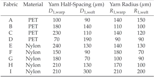
concen-Table 1: The base material used for fabric construction, values of the yarn half spacing in
the warp (D1,warp) and weft (D1,weft) directions, and the yarn radius in the warp (R1,warp)
and weft (R1,weft) directions for the fabrics used in this study. Yarn half-spacing (D) and
radius values (R) have an uncertainty of±5 µm. Corresponding images are provided in
the Supporting Information.
Fabric Material Yarn Half-Spacing (µm) Yarn Radius (µm)
D1,warp D1,weft R1,warp R1,weft
A PET 100 90 140 150 B PET 180 140 110 100 C PET 230 110 140 120 D PET 70 190 90 90 E Nylon 240 130 140 130 F Nylon 150 90 180 70 G Nylon 180 70 100 90 H Nylon 210 130 170 100 I Nylon 210 300 210 200
tration of 20 mg/ml was prepared using the HCFC solvent Asahiklin (AK225, Asahi Glass Company). All fabrics were initially dipped in the fluorodecyl POSS/Tecnoflon solution for 2 minutes, and then allowed to dry in ambient atmospheric conditions for 5 minutes.
The fluorodecyl POSS/Tecnoflon dip-coating treatment deposits a thin (∼ 200 nm)
uni-form conuni-formal oloephobic coating4 onto the individual fibers of the woven fabric, and
thus allows us to control the wetting behavior across the various fabrics, without altering the underlying geometrical structure. The Tecnoflon is a fluoroethyene copolymer that
acts as an elastomeric binder conferring flexibility and durability to the coating.35
To impart random corpuscular microstructures (Dmean ≈5 µm) on the fabrics a
spray-coating technique previously developed in our laboratory was used.36 A 50/50 wt%
so-lution of fluorodecyl POSS/Poly(methyl methacrylate) (PMMA; Mw = 102 kg mol−1)
with a total solids concentration of 50 mg/ml was dissolved in Asahiklin. This solution was lightly sprayed onto the fabrics from a distance of 20 cm until a layer of spherical microtexture was deposited onto the individual fibers of the fabric.
Contact Angle Measurements
Contact Angle (CA) measurements were carried out using a ram´e-hart goniometer
af-ter vertically depositing a drop of V ≈ 5µL on each fabric sample. The probe liquids
used in this study were reagent grade deionized (DI) water, dimethyl sulfoxide (DMSO), methylene iodide, ethylene glycol, rapeseed oil, dimethyl methylphosphonate (DMMP), hexadecane, decane, tributyl phospate, methanol, 2-propanol, and heptane. The reported contact angle values represent averages over four or more measurements taken at differ-ent locations on the sample.
Theoretical Framework
Flat substrates with low surface energies on the order γsv ∼10 mN/m exhibit
equilib-rium Young’s contact angles with water drops (γlv = 72.1mN/m) that are larger than
90◦.26,27However, drops of various oils and low surface tension liquids (e.g., hexadecane;
γlv = 27.5mN/m) deposited on the same low energy surface result in Young’s contact
angles that are much smaller (i.e., θE < 90◦).35 Therefore, chemically treated flat surfaces
with very low surface energies are typically still oleophilic to liquids with surface
ten-sions γlv !30 mN/m. The introduction of textured, re-entrant surface topographies (e.g.,
nanonails, hoodoos, or the cylindrical fibers and yarns of woven fabrics) is necessary to enable the low surface tension liquid drop to rest in a metastable non-wetting
Cassie-Baxter state.1,16
Cassie and Baxter24modeled the behavior of liquid drops on monofilament textiles as
an array of parallel cylinders supporting a composite solid-liquid-air interface to obtain
their well-known equation, which can be expressed in the following form:16
cos θ∗ = −1+ 1
Here, θ∗ is the macroscopic apparent contact angle exhibited by the liquid drop
de-posited on the array of cylinders, θE is the corresponding Young’s contact angle on a
flat surface exhibiting an identical surface chemistry to that of the cylinder, and D∗ =
(R+D)/R is a dimensionless geometric parameter defined in terms of the half-spacing
between the cylinders D and the radius of the cylinder R. This simple one-dimensional cylindrical model is widely used to model the wetting of monofilament textiles.
However, Michielsen and Lee20 draw attention to the hierarchical nature of
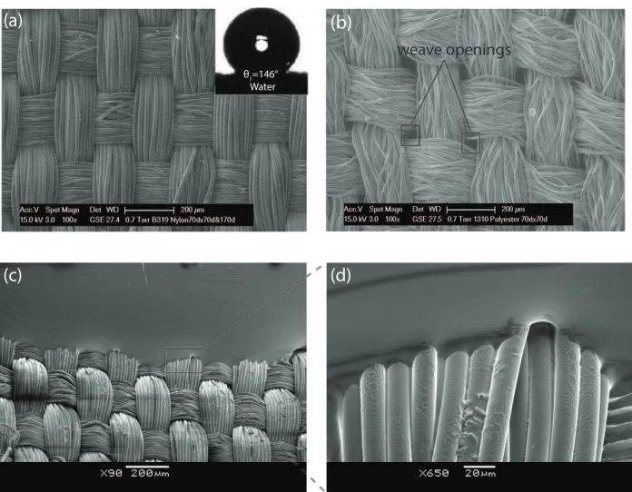
multifil-ament woven fabrics, for which equation 1 cannot directly be applied and needs to be recursively modified. We illustrate the hierarchical structure of a typical fabric in Figure 1, where we show a series of Scanning Electron Micrographs (SEMs) on a multifilament woven fabric that demonstrates two levels of hierarchy corresponding to the bundled yarn and individual fibers. Figure 1a is an SEM of a woven nylon-based fabric (Fabric G) consisting of a uniform weave structure. The fabric has been dipcoated in a solution of 50 wt% fluorodecyl POSS/Tecnoflon to deposit a conformal low-surface-energy coat-ing. The uniform and regular weave that we observe in Fabric G is contrasted to a more loosely-woven polyester-based fabric (Fabric B) that is marked by the presence of weave openings between the warp and weft directions. The presence of these weave openings is captured by changes to the half spacing and radius of the bundled yarns. Therefore, at a macroscopic or ’coarse-grained’ level, we expect the geometry of the bundled yarn to influence the wetting behavior of liquid drops on the woven fabric. In Figures 1c and 1d, we show micrographs at two different magnifications of a cured drop of a silicone
elas-tomer (Sylgard 184, Dow Corning; γlv ≈25 mN/m) that has been deposited vertically on
the dip-coated oleophobic Fabric G, and subsequently heat treated for 20 minutes at 80◦C
to cure. At this higher level of magnification, the inner hierarchical cylindrical structure of the individual fibers is immediately evident. The fibers are densely packed, with radii that are an order of magnitude smaller than the bundled yarn. In Figure 1d, we show the topographical details of the wetted perimeter of the cured silicone drop on the collection
(a)
BW 4040 PET PS: 10 AP: 5 C: 156x88 Y: 70dx70d(a)
(b)
weave openings(c)
(d)
θ1=146° WaterFigure 1: (a) Scanning Electron Micrograph (SEM) of a plain-woven Nylon fabric (Fabric G) which has undergone a hydrophobic treatment by dipcoating in a 50/50 fluorodecyl
POSS/Tecnoflon solution. The inset shows a drop of water (γlv = 72.1 mN/m)
verti-cally deposited onto the fabric exhibiting a high apparent contact angle of θ1 =146◦; (b)
SEM of a Polyester fabric (Fabric B) exhibiting randomly located weave openings in the woven structure; (c,d) SEM micrographs of the contact line structure of a cured PDMS
(γlv ≈ 25 mN/m) drop resting on Fabric G at different magnifications corresponding to
different textural length scales in the fabric. (c) illustrates the shape of the contact line at a length scale corresponding to the bundled yarn of the woven fabric, while (d) captures the tortuosity of the contact line at the scale of the individual fibers within a bundle.
of individual fibers. These small, tightly bundled fibers play a key role in determining the critical surface tension at which a millimetric liquid drop transitions to the Wenzel state and is subsequently imbibed into the fabric.
The self-similar cylindrical structures that are observed in Figure 1(a-d) suggest that Eqn. 1 needs to be recursively applied to the smaller individual fibers and larger bundled yarn to predict the apparent contact angles of liquid drops sitting on multifilament woven
fabrics. Here, we apply the recursive framework developed by Herminghaus22to expand
on the work of Michielsen and Lee.20 Thus, systematically developing a set of equations
that can model both multifilament woven and nanotextured woven fabrics.
Modeling Apparent Contact Angles on Multifilament Woven Fabrics
In Figure 2, we illustrate schematically a liquid drop resting on an oleophobic
multi-filament fabric. The first level of hierarchy (n = 1; cf. Figure 2a) captures the
wo-ven geometry of the yarn which is modeled as an array of parallel cylinders with a
ra-dius R1, half-spacing D1and characterized by the dimensionless geometrical parameter
D∗1 = (R1+D1)/R1 . The value of D1∗ is related to the weave angle α (between the
warp/weft directions and the fabric plane) as D∗1 = cot α. Variations in this geometric
parameter D1∗allows us to account systematically for the wetting effects of various weave
constructions and the presence of weave openings on the non-wettability of different
fab-rics. A small value of D∗1corresponds to fabrics with a very fine weave, while large values
of D∗1 indicate a looser weave with higher incidences of weave openings. At the second
level of hierarchy (n=2; Figure 2b), we model the packing of individual fibers into
bun-dles with radius R2and mean half-spacing D2, that are characterized by a dimensionless
length scale D2∗ = (R2+D2)/R2. A consequence of constructing the yarn as a collection
of tightly bundled fibers is that, for multifilament woven fabrics, the value of the
inter-fiber spacing D2 → 0 (as seen in Figure 1d) which leads to D∗2 → 1. The local effective
denoted as θ2. For the plain weave multifilament fabrics that we have discussed so far, the
hierarchy of equations terminates at n =2. The equilibrium contact angle that
character-izes the nature of the coating applied to the individual fibers is denoted as θE. To define
canonically the hierarchical nature of these plain weave fabrics, we denote these two-level cylindrical structures as a CC fabric, as we recursively apply eq 1 twice. Therefore, the set of equations that govern the wetting of a liquid drop on a multifilament woven fabric (or
CC fabric) with n=2 is given by eq 2a and 2b:
cos θ1 = −1+ 1
D∗1 [(π−θ2)cos θ2+sin θ2] (2a)
cos θ2= −1+ [(π−θE)cos θE+sin θE] (2b)
Eq 2a predicts the macroscopic apparent contact angle θ1of a droplet placed on the CC
fabric while eq 2b governs the apparent contact angle θ2of the liquid meniscus on an array
of individual fibers that are tightly bundled (with D∗2 → 1). For a wide range of liquids,
the mapping implied by eqs 2a and 2b amplifies the local equilibrium contact angle (θE)
to a new (larger) value of θ1 on the hierarchically textured surface, thus enhancing the
non-wettabilty or “repellency” of the fabric. We will extend this model to a third level of hierarchy as shown schematically in Figure 2(d).
Pressure driven transition from the Cassie-Baxter to Wenzel state on
multifilament fabrics
The equilibrium contact angle θEcan be lowered by (i) depositing liquid drops with lower
surface tensions (such as oils) for a given chemical coating on the fibers or (ii) modifying
the surface chemistry of the fibers resulting in larger values of surface energy (γsv) for a
given liquid drop. In either scenario, as θE decreases, the liquid drop will progressively
(a)
(b)
Tightly Woven Loosely Woven Nanostructured Fibers(c)
2R 3 2D3 Section A-A’ A A’ 1 R 2 2D1 2 D 2 2R2 D2∗= (R2+D2)/R2 2 R 2 D2 ≈0 D2∗≈1 3 R )/ 3 D + 3 R = ( 3∗ D 1 ≫ 3∗ D 1 R 2 2D1α
D∗1 = (R1+ D1)/R1 = cot αFigure 2: (a) Schematic of an axisymmetric liquid drop on a model sinusoidal non-wetting woven fabric showing different levels of hierarchy. The AA’ plane illustrates the cross-sectional view of the periodic woven structure, consisting of bundled yarns of diameter
2R1separated by a distance 2D1. The dimensionless geometric parameter D∗1is related to
the angle of weave α as D∗1 = (R1+D1)/R1 =cot α; (b) Schematic of the second level of
hierarchy depicting the location of the contact line resting on the individual non-wetting fibers which compose the yarn. The fibers are modeled as parallel cylinders of diameter
2R2separated by a distance 2D2. The packing of the fibers is governed by the
dimension-less geometric parameter D2∗ = (D2+R2)/R2which is taken to be D∗2 ≈1 (corresponding
to the tightly woven limit) consistent with the SEM micrographs shown in Figure 1d; (c) Schematic of a third level of textural hierarchy, with the individual fibers decorated by an
array of spherical micro- or nano-particles of radius 2R3 and a mean spacing distance of
2D3. The packing of the spherical particles is governed by the dimensionless parameter
wetted Wenzel state. The Cassie-Baxter to Wenzel transition is driven by the pressure differential that exists across the composite liquid-air interface, and occurs either by a
depinning or sagging mechanism.2,37 This transition occurs as a sequential cascade in
hierarchical structures, with the larger air pockets trapped between textural features at the
larger length scales (n = 1) readily prone to collapse. When liquids with large values of
θE(i.e., high surface tension liquids) are deposited on multifilament fabrics, they wet only
the tops of the woven yarns. This has been demonstrated both by direct visualization and
finite element simulations of water on arrays of nonwetting cylinders.38 However, upon
decreasing the value of θE, the meniscus descends into the texture until it transitions to
resting on the individual fibers that comprise the warp (weft) yarn that lies underneath two adjacent weft (warp) yarns (see Figure 1c). Therefore, the eventual wetting transition
to the fully wetted Wenzel state is determined by the smaller length (n = 2, fibers) on
heirarchical structures such as multifilament woven fabrics. The critical (or breakthrough)
pressure difference (∆Pb) across the liquid-air interface at which the drop irreversibly
transitions to the fully-wetted Wenzel state at the largest defect site can be expressed for
an array of parallel cylinders as:37,38
∆Pb = (γlv/R2) [sin(θE−ϑc)/(D∗
2 −sin ϑc)] (3)
Where R2 is the radius of the fiber at the second level of hierarchy and ϑc is the
crit-ical angular position of the contact line on the cylinder at the onset of transition.37 At
this critical angular position, the transition can occur by either a depinning or a sagging mechanism.
When a liquid drop of surface tension γlv and radius rdrop ∼ Vdrop1/3 is deposited on an
array of cylinders, the Laplace pressure inside the drop is ∆Pl = 2γlv/rdrop. A
sponta-neous transition to the fully-wetted Wenzel state is expected to occur when the Laplace
pressure (∆Pl) exceeds the breakthrough pressure (∆Pb). The equilibrium contact angle
to a loss of the non-wetting character of the fabric) is denoted as θ(Ec). A crucial feature of the wetting transition arises from the thermodynamic metastability of the non-wetting
Cassie-Baxter state described by eq 1 when θE <90◦ (e.g., most oils) and a wetting
transi-tion can be nucleated by a single localized defect.16 The inverse dependence of eq 3 on the
feature length scale (R2) means that the largest defect site in the periodic array acts as the
initial nucleation site for the Cassie-Baxter to Wenzel transition. In our calculations below,
we assume a defect-free tightly bundled packing of uniform radius fibers with D∗2 ≈1.
In the experiments performed, the drop radius of the probe liquid is fixed as rdrop ≈
1.5 mm. For a liquid drop of heptane (γlv = 20.1 mN/m; θE = 63◦) resting on a planar
array of cylinders corresponding to the smallest length scale in the fabric (i.e., n=2; with
a fiber spacing ratio of D2∗ ≈1 and a fiber radius of R ∼10 µm), the expected ratio of the
breakthrough pressure to the Laplace pressure is ∆Pb/∆Pl ≈36, which suggests that the
drop is expected to be stable. However, the tight packing of the bundled fibers provides an alternate route to the Wenzel transition by a wicking mechanism. When the apparent
contact angle θ2 → 0 on the individual fibers shown in Figure 2b with decreasing values
of θE, the Cassie-Baxter state supported at the second level of hierarchy (i.e., n = 2,
be-tween the tightly packed fibers) undergoes a wetting transition and the liquid is imbibed completely into the fiber bundle spreading along the individual fiber filaments. Setting
cos θ2=1 in eq 2b, we solve this implicit equation to obtain a critical value of θE(c) ≈57.2◦
when this wetting transition occurs. Physically, this implies that a liquid drop with an equilibrium contact angle smaller than this critical value will completely wet the individ-ual fibers and be imbibed into the fabric irrespective of the larger scale geometry of the
weave. The loss of the Cassie-Baxter composite state at the n =2 level of hierarchy results
in the liquid drop rapidly wicking along the individual fibers until the entire fabric is wet-ted. Therefore, even if a liquid drop initially exhibits a fairly large macroscopic apparent
contact angle on the fabric (i.e., θ1 ≫90◦), as the equilibrium contact angle θEapproaches
Results and Discussion
Characterization of dip-coated oleophobic fabrics using goniometric
mea-surements
Apparent contact angle measurements were performed on each of the nine dip-coated fabrics using probe liquids with sequentially decreasing values of surface tension from
water (γlv = 72.1 mN/m) to n-heptane (γlv = 20.1 mN/m). In Table 2, we report the
measured values of the macroscopic static contact angles (θ1) on the various dip-coated
fabrics. We also list the corresponding values of the equilibrium contact angle (θE)
mea-sured on flat substrates spin-coated with the same fluorodecyl POSS/Tecnoflon solution. While the equilibrium contact angle on flat surfaces can be measured fairly accurately via
goniometry (∆θE = ±1◦), difficulties in precisely establishing the position of the
three-phase contact line on the textured fabrics results in larger uncertainties in the
measure-ment of apparent contact angles (∆θ1 = ±5◦).
All dip-coated fabrics are strongly water repellent exhibiting large macroscopic
con-tact angles of θ1 ≈135◦with water drops and are also resistant to wetting by low surface
tension hexadecane drops (γlv = 27.5 mN/m; θ1 ≈ 95◦), emphasizing the oleophobic
non-wetting character that the dip-coating process confers on the nylon and PET based materials. As mentioned earlier, the dip-coating process that conformally deposits the
fluorodecyl POSS/Tecnoflon coating ensures that the value of θE corresponding to a
par-ticular probe liquid is systematically controlled. Therefore, the values of θE are identical
across all fabrics and any variation in the experimentally measured macroscopic contact
angle θ1is attributable to the geometry of the outer weave, and in particular to the value
of D∗1 (related to the yarn weave angle α as D∗1 =cot α). In each of the fabrics, the
macro-scopic apparent contact angle decreases with lower surface tension liquid drops (i.e.,
cor-respondingly smaller values of θE), indicative of progressively larger solid/liquid wetted
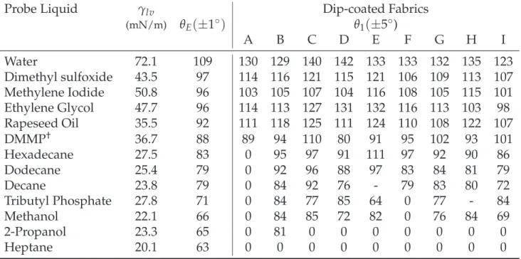
Table 2: Summary of the surface tension (γlv), equilibrium contact angle on a flat
fluo-rodecyl POSS/Tecnoflon coating (θE), and apparent contact angles (θ1) on the nine PET
and Nylon fabrics fabrics for the thirteen probe liquids of interest. (†- Dimethyl
methylphos-phonate)
Probe Liquid γlv Dip-coated Fabrics
(mN/m) θE(±1◦) θ1(±5◦) A B C D E F G H I Water 72.1 109 130 129 140 142 133 133 132 135 123 Dimethyl sulfoxide 43.5 97 114 116 121 115 121 106 109 113 107 Methylene Iodide 50.8 96 103 105 107 104 116 108 105 115 101 Ethylene Glycol 47.7 96 114 113 127 131 132 116 113 103 98 Rapeseed Oil 35.5 92 111 118 125 111 124 110 108 122 107 DMMP† 36.7 88 89 94 110 80 91 95 102 93 101 Hexadecane 27.5 83 0 95 97 91 111 97 92 90 86 Dodecane 25.4 79 0 92 96 88 97 83 84 81 79 Decane 23.8 79 0 84 92 76 - 79 83 80 72 Tributyl Phosphate 27.8 71 0 84 77 85 64 0 77 - 84 Methanol 22.1 66 0 84 85 72 82 0 76 84 69 2-Propanol 23.3 65 0 81 0 0 0 0 0 0 0 Heptane 20.1 63 0 0 0 0 0 0 0 0 0
transition occurs to the Wenzel state. We perform a non-linear regression of the measured
values of θ1 and θE using eq 2a and 2b to obtain a best-fit estimate of the dimensionless
textural parameter D∗1 that describes the spacing between the yarns for each fabric.
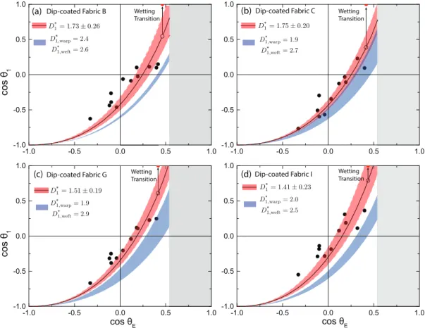
The results of these regression fits are depicted graphically in Figures 3(a-d). The cosines of the experimentally measured values of the macroscopic apparent contact angle
(cos θ1) are plotted against the cosines of the equilibrium contact angles (cos θE) for four
representative dip-coated nylon (Fabrics G and I) and polyester (Fabrics B and C) fabrics with differing weaves. We can use the recursive model described by eq 2a and 2b to obtain two predicted non-wetting curves (corresponding to the warp and weft directions) using
values of R1 and D1 that are obtained from microscopy (see Table 1). These curves are
plotted as solid blue lines in Figures 3(a-d), and represent the upper and lower bounds to
the microscopy-based model predictions of θ1 (bounding the region shaded in blue). In
with the microscopy based estimates along the warp/weft directions.
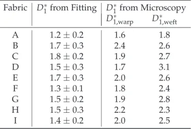
Table 3: Fitted values of D∗ and corresponding values determined from microscopy for
the nine PET and nylon fabrics of interest.
Fabric D1∗from Fitting D∗1 from Microscopy
D∗1,warp D∗1,weft A 1.2±0.2 1.6 1.8 B 1.7±0.3 2.4 2.6 C 1.8±0.2 1.9 2.7 D 1.5±0.3 1.7 3.1 E 1.7±0.3 2.0 2.6 F 1.3±0.1 1.8 2.4 G 1.5±0.2 1.9 2.8 H 1.5±0.3 2.2 2.3 I 1.4±0.2 2.0 2.5
As is evident from Figures 3(a-d) and Table 3, while the best-fit estimates of D1∗
us-ing the simple hierarchical model of adjacent parallel cylinders qualitatively captures the trends in the non-wetting behavior of the various fabrics, these values are systematically smaller than values that are obtained from microscopy along the warp and weft direc-tions. This result is expected and stems from the fabric possessing three-dimensional structures that protrude into the liquid increasing the real solid fraction of the interface
and decreasing the effective D∗1. A more accurate model would require detailed
calcu-lation of the topography of the wetted patches that form on the true woven structure
using a program such as Surface Evolver.40 However, despite the significant
simplifi-cation involved in our 1D cylindrical array model, some important insights underlying the non-wetting behavior of the fabrics can be obtained by application of the
hierarchi-cal model. First, despite the differences in fabric construction the values of D∗1,warp and
D∗1,weftall lie between 1.6 ≤ D∗ ≤ 3.1. Our best fit values of D∗1 are similar for all fabrics (between 1.2 and 1.8), and this uniformity is expected due to the very similar nature of the weave angles in all plain weave fabrics, where the geometry of the tight weave offers
weave angle of α ≈ 30◦ (corresponding to a value of D1∗ ≈ 1.7). This intrinsic constraint on the magnitude of apparent contact angles that can be attained on a plain weave fabric requires the introduction of an additional micro- or nanotextured length scale to further enhance the nonwetting character of fabrics.
-1.0 -0.5 0.0 0.5 1.0 -1.0 -0.5 0.0 0.5 1.0 -1.0 -0.5 0.0 0.5 1.0 -1.0 -0.5 0.0 0.5 1.0 -1.0 -0.5 0.0 0.5 1.0 -1.0 -0.5 0.0 0.5 1.0 -1.0 -0.5 0.0 0.5 1.0 -1.0 -0.5 0.0 0.5 1.0 co s θ1 co s θ1 cos θ E cos θE D*1= 1.41 ± 0.23 D* 1,warp= 2.0 D* 1,weft= 2.5 D1*= 1.51 ± 0.19 D*1= 1.73 ± 0.26 D*1= 1.75 ± 0.20 D*1,warp= 1.9 D* 1,weft= 2.9 D* 1,warp= 2.4 D* 1,weft= 2.6 D* 1,warp= 1.9 D* 1,weft= 2.7 Dip-coated Fabric B Dip-coated Fabric C
Dip-coated Fabric G (a) (b) (c) (d)Dip-coated Fabric I Wetting Transition Wetting Transition Wetting Transition Wetting Transition
Figure 3: Plot of the cosine of the apparent contact angle cos θ1 against the equilibrium
contact angle cos θE on four dip coated fabrics (a) Fabric B (b) Fabric C (c) Fabric G (d)
Fabric I. The solid black lines depict the best fit of D1∗to eq 2 for each of the fabrics (Fabric
B: D1∗ = 1.73±0.26; Fabric C: D∗1 = 1.75±0.20; Fabric G: D∗1 = 1.51±0.19; Fabric I:
D∗1 =1.41±0.23) with the 95% confidence interval band shaded in red. We also plot the
cosine of the apparent contact angles predicted by the D∗values measured by microscopy
(blue shaded region). The upper blue line results from the measured D∗value in the warp
direction and the lower blue line results from the value measured in the weft direction. The analogous figures for the remaining five fabrics are shown in the Supporting Infor-mation.
Figure 3 and Table 2 also show clearly that for a probe liquid with sufficiently low surface tension, there is a sudden and spontaneous transition to the fully-wetted
super-oleophilic Wenzel state; the liquid drop readily wicks and spreads along the fabric,
result-ing in a 0◦macroscopic contact angle, indicated by the vertical arrow in Figures 3(a-d). For
the set of fabrics C-E and G-I, this wetting transition occurs upon contact with propanol
(γlv = 23.3 mN/m; θE = 65◦), while fabric B wets with n-heptane (γlv = 20.1 mN/m;
θE =63◦).
In each of the fabrics, we also observe that the critical contact angle θE(c) at which a
wicking failure occurs is above the predicted limit of θ(Ec) = 57.2◦, consistent with the
hierarchical CC model of the woven fabric. The variation of the macroscopic contact
angle with a variety of liquids on woven fabrics is captured by the single parameter D∗1in
the CC model. However, the tight bundling of the individual fibers from which the yarn
is constructed (i.e., D∗2 ≈1) imposes a lower limit on the surface tension of the contacting
liquid that can exhibit oleophobicity.
θ2 with D *
2 = 1
θ1 for plain woven fabric
θ1 for nanotextured fabric
D E
Region inaccesible to plain woven fabrics
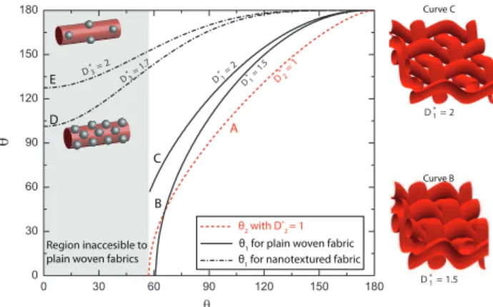
Curve B Curve C =1.5 1 * D =2 1 * D =1 2 * D B C A =1.7 3 * D = 2 3 * D = 2 1* D = 1.5 1 * D
Figure 4: Plot of the contact angles θn against the equilibrium contact angle θE(predicted
by the set of eq 4-5) on a fabric with n levels of hierarchy. The dotted red line A
corre-sponds to the variation of the contact angle on the individual fibers θ2with θE(predicted
by eq 2b) for the tightly woven limit with D∗2 = 1. The solid black curves B and C
de-pict the variation of θ1 for the two values of D1∗ = 1.5 and D∗1 = 2, respectively, on the
plain-woven fabrics with n =2. The model sinusoidal woven geometries corresponding
to curves B and C are shown alongside the plot. The shaded region signifies when the
individual fibers are fully wetted (θE !57◦) and is inaccessible to the plain weave fabric
with two levels of hierarchy n =2. The dashed black lines show the variation of θ1with
θEon woven fabrics consisting of textured fibers with n=3 for two nanoparticle spacings
Adding a third length-scale of texture to woven fabrics
The undesirable wetting transition, in which the liquid spreads along the closely packed monofilaments of the bundled yarns poses a geometric constraint on the liquid-repellency of woven fabrics. We again emphasize that merely modifying the surface energy by ap-plying various low surface energy coatings is not sufficient to prevent this transition; the introduction of a third level of hierarchy by texturing the individual bundled fibers is re-quired to further amplify the macroscopic contact angle given by the recursive equation set (eq 2). This can be achieved, for example, by the introduction of spherical nanopar-ticles embedded on the fibers. The recursive equations which determine the apparent
contact angle θn at each stage of the n generations of the hierarchical self-similar structure
are given by eq (4) for a canonical cylindrical geometry (C):4,20
cos θn = −1+ 1
D∗n [(π−θn+1)cos θn+1+sin θn+1] (4)
And eq (5) for a spherical geometry (S):2
cos θn = −1+ 1 (D∗n)2 ! π 2√3(1+cos θn+1) 2" (5)
In each case the effective contact angle θnthat can be achieved depends on the
geome-try of the texture at this nth scale, and the effective contact angle θn+1that is generated by
the next, higher order(n+1)thlevel of texture. In each case the hierarchical equation set
is truncated at the finest scale when the surface is locally flat and θn+1→θE. In figure 2c,
we show one possible realization using spherical nanoparticles to achieve a third genera-tion of hierarchy in the woven fabric, which we denote as a CCS fabric, as we recursively
apply eq 4 for n=1, 2 and eq 5 at n =3. The spherical nanoparticles are embedded into,
or deposited onto, the individual fibers of the fabric, and are characterized by a radius
R3, half-spacing D3 and a corresponding dimensionless parameter D∗3 = (D3+R3)/D3
assume that the chemical coating applied to the spherical nanoparticles is characterized
by the same equilibrium contact angle θE that is used for the fibers and yarns. The
recur-sive equations governing the nanoparticle textured CCS fabric (conceptualized in Figure 2c) can then be written out explicitly as:
cos θ1 = −1+ 1
D∗1 [(π−θ2)cos θ2+sin θ2] (6a)
cos θ2 = −1+1 1[(π−θ3)cos θ3+sin θ3] (6b) cos θ3 = −1+ ( 1 D∗3)2 ! π 2√3(1+cos θE) 2 " (6c)
where θ3refers to the apparent contact angle on the individual nanotextured fibers and
we assume a tightly woven structure so that D∗2 →1. The introduction of the third level of
structure removes the wicking constraint on oleophobicity, and allows for the design and realization of fabrics which can support liquid drops with very low surface tensions in the metastable Cassie-Baxter state. While eq 6c is written for a CCS nanotextured fabric, an analogous set of equations can be written for a CCC fabric, where the third generation of nanotexture consists of hairy cylinders. In Figure 4, the curves D and E show the variation
of the macroscopic apparent contact angle θ1 with the equilibrium contact angle θE for a
spherically nanotextured woven CCS fabric described by eq (6a)-(6c) with D∗1 =2, D∗2 =1
and two different values of D∗3. Larger values of D3∗result in a lower density of spherical
nanoparticles, illustrated by the schematic in the inset of Figure 4. The introduction of the nanotextured length scale greatly enhances the apparent contact angle for the CCS fabric that can be achieved when compared to the equivalent CC fabric with the same value of
D∗1 (shown in curve C). In addition, the critical equilibrium contact angle at which the
wetting transition occurs in the third generation of hierarchy is controlled by the packing of the spheres.
In order to determine the criteria for the pressure driven wetting transition on the
ar-ray of nanospheres, we adapt the work of Butt et al.2 on vertically sintered spheres. In
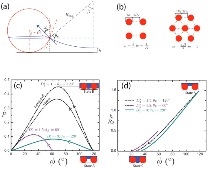
Figure 5, we show an illustration of the liquid meniscus between an array of spherical nanoparticles. The position of the contact line on the sphere is a function of the angle
φ between the contact line, the center of the sphere, and the base of the sphere, and is
expressed as y(φ) = R3(1−cos φ). The value of φ, which sets the location of the
con-tact line, is determined by a balance of the capillary force pulling the interface upwards against the pressure difference across the interface and can be determined from the
im-plicit equation:2,41
ˆ
P= sin φ sin(θE−φ)
#alD∗32−sin2φ$ (7)
where ˆP = P/Pref and Pref = 2γlv/R3 is a reference pressure scale that depends on
the liquid surface tension γlv and particle size R3, and al is a lattice constant with al =
(2√3/π)for a hexagonally packed array of spheres and al = (4/π)for a square packing.
When there is no external pressure difference (i.e., ˆP =0), the liquid meniscus is flat and
the contact line wets the spherical nanoparticle at a height determined by φ=θE. As ˆP is
increased, the value of φ (and therefore, the position of the interface y) steadily decreases according to eq 7 until the Cassie-Baxter state undergoes a transition to the Wenzel state. This transition can occur in one of the following two ways: (i) a depinning mechanism when the pressure exceeds the maximum capillary force that can be supported by eq 7 or (ii) a capillary bulge mechanism when the pressure induces sufficient curvature of the liquid meniscus causing it to touch the underlying substrate on which the spheres are embedded.
In Figure 5c, we plot ˆP determined from eq 7 as a function of φ for different values
of the equilibrium contact angle θE and the dimensionless spacing parameter D∗3. In each
of the curves, we see that there is a maximum value of ˆP = Pˆmax at a particular value of
3 D 2 3 R 2 3 D 2 3 R 2 = 1 l b ; π 3 √ 2 = l a 2 √1 = l b ; π 4 = l a
(b)
φ e θ ω 3 R β sag R h(a)
P
ˆ
φ (°)
φ (°)
(c)
hexagon al squar e ◦ = 120 E θ = 1.5; 3∗ D ◦ = 60 E θ = 1.5; 3 ∗ D ◦ = 120 E θ = 3; 3 ∗ D State B State A 3 R h ◦ = 120 E θ = 3; 3 ∗ D ◦ = 60 E θ = 1.5; 3∗ D ◦ = 120 E θ = 1.5; 3 ∗ D State A State C(d)
Figure 5: (a) Schematic of the meniscus of a liquid drop resting on a sphere of radius
R3 possessing an equilibrium contact angle θE. The contact line subtends an angle of φ
with the center of the sphere. The pressure differential across the meniscus ∆P drives the
formation of the curved meniscus with a radius of curvature Rsag that subtends a
half-angle β with the vertical. The bottom of the meniscus is at a height h above the bottom surface. (b) Schematic of the top view of an array of spheres arranged in a square and
hexagonal lattice. The geometrical lattice parameters al, blare discussed in the main text.
(c) Plot of the dimensionless pressure difference ˆP vs the angle φ subtended by the contact
line to the center of the sphere. Initially, in the absence of any pressure differential ( ˆP =0),
the meniscus is flat and is located at φ = θE (labeled State A). The value of φ decreases
with increasing pressure difference ˆP until the pressure reaches a maximum at φ = φd
(labeled State B) which corresponds to a depinning transition. (d) Plot of the minimum meniscus height above the bottom substrate h against the subtended angle φ showing a
gradual decrease until the bottom of the meniscus touches the substrate (i.e., h =0) when
φ = φs, signifying a sagging transition (shown in State C). In each of the curves in Fig.
5(c,d), the solid, dashed and dash-dot lines correspond to various values of D∗3 and θEas
indicated in the figure. Unless otherwise noted, a hexagonal lattice was assumed for the sphere packing.
difference that can be supported is larger for a hexagonal packing of spheres compared
to a square array. If the dimensionless pressure difference ˆP across the meniscus is larger
than the value ˆPmax, the capillary force acting at the contact line will be unable to balance
the pressure force at the interface for any point on the sphere. The composite interface therefore depins and wets when the meniscus physically corresponds to state B depicted
in the inset of Figure 6. The depinning transition ˆPdep is therefore the maximum value of
ˆ
P at which d ˆP/dφ = 0. An expression for the depinning angle φm is provided by Butt
et al.. However, while estimating the capillary bulge pressure, Butt et al. assume that the
location of the contact line is determined by φ = θE, an assumption which is valid only
when ˆP ≪ 1. We can derive a more general analytical expression for the height h of the
bottom of the curved meniscus (with radius of curvature Rsag) above the substrate (as
shown in Fig. 5a) as:
h =R3(1−cos φ) −Rsag(1−cos β) (8a)
sin β=# R3/Rsag$[bl(D∗3−1) +1−sin φ] (8b)
ˆ
P=#R3/Rsag$ (8c)
with bl = 1 for a hexagonal lattice and bl = 1/√2 for a square lattice. We show the
variation of the height h with φ as an external pressure difference is applied in Figure 5d.
Initially, when there is no external pressure ( ˆP =0), the bottom of the meniscus starts at
a height h =R3(1−cos θE)above the substrate, depicted by State A in the inset of Figure
5d. As the pressure is gradually increased, the meniscus curvature increases and height decreases. Eventually the meniscus can touch down on the substrate, corresponding to
h = 0, even if the pressure is still increasing (i.e., d ˆP/dφ < 0 in Fig. 5). This corresponds
to a sagging transition, and at this point the contact line on the sphere subtends an angle
φ=φs. The value of φscorresponds to the intersection of the curves in Figure 5d with the
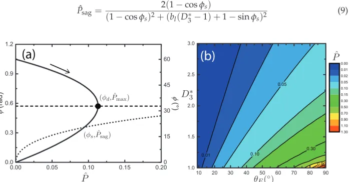
pressure difference ˆPsagat which the touchdown of the meniscus first occurs is given by: ˆ Psag = 2(1−cos φs) (1−cos φs)2+ (bl(D∗3−1) +1−sin φs)2 (9)
P
ˆ
θE(◦) 3∗D
P
ˆ
(a)
(b)
) max Pˆ , d φ ( ) sag Pˆ , s φ (Figure 6: (a) Plot of the location of the contact line characterized by φ against
dimension-less pressure difference ˆP for hexagonally packed spheres with D3∗ = 1.5 and θE = 60◦.
The solid curve describes the evolution of the meniscus with pressure via eq 7, where the
meniscus initially evolves from φ = θE when ˆP = 0. The horizontal dashed line
corre-sponds to the depinning transition limit of φ = φd. The dotted curve plots the variation
of the pressure as a function of φ corresponding to a sagging transition (eq 9). The in-tersection of the solid line and the dotted line determines the sagging transition limit of
φ=φs; for these paramter values the depinning transition is encountered first (as shown
by the solid black circle) (b) Contour plot of the dimensionless breakthrough pressure for
various values of the dimensionless geometric spacing D3∗and equilibrium contact angle
θE. The breakthrough mechanism corresponds to a depinning transition over the entire
range of D3∗and θEshown.
In summary, when there is no external pressure applied, the meniscus initially sits flat
at a height h corresponding to φ = θE (state A in Fig. 5). As the pressure is gradually
in-creased, the meniscus bends and deforms downward and φ decreases. The mode of tran-sition from the Cassie-Baxter state to the Wenzel state is determined by the larger of the
two angles φs and φd (corresponding to the depinning and sagging failure mechanisms,
respectively). In Figure 6a, we illustrate this behavior for an array of hexagonally packed
increased. The solid line shows the evolution of the location of the meniscus with applied
pressure from an initial value of φ = θE determined by eq 7. The horizontal dashed line
indicates the value of φdat which the depinning transition occurs and the dotted line is a
plot of eq 9 as a function of φ. The sagging transition, and the value of φs is found from
the intersection of this curve with eq 7. As the value of φd >φs, the depinning transition
occurs first for this particular configuration. By performing a series of such calculations
varying 1 ≤ D3∗ ≤ 4 and 0 ≤ θE ≤ 90◦, we observe that the Cassie-Baxter to Wenzel
transition occurs primarily by the depinning transition, even on an single monolayer ar-ray of spheres. Our calculations show that as the contact line descends along the surface of the wetted spheres, the smaller wetted perimeter is unable to support the additional pressure force on the curved liquid-vapor surface area and leads to a depinning transition
before the lowest point of the meniscus touches the underlying substrate (h = 0 or state
C in Fig. 5d). This observation of the depinning behavior on an array of spheres is also consistent with the result of Butt et al., who show that the depinning transition is the dom-inant mode on higher aspect ratio structures, such as an array of two vertically sintered
spheres. In Figure 6b, we show contour plots of the dimensionless pressure ˆPd(θE, D3∗)
at which depinning occurs. For a fixed surface coating (which fixes the value of θE), the
value of the depinning pressure ˆPd steadily decreases as the dimensionless spacing ratio
increases. Following the procedure of Butt et al., we can obtain an analytical estimate of
the breakthrough pressure in the limit of large D3∗ ≫ 1. Eq 7 simplifies to the
expres-sion, ˆP∼=sin φ sin(θE−φ)/(alD∗32)and we can obtain an expression for the dimensional
depinning pressure in this limit as:
Pd =% 2γlv R &' 1 alD3∗2 ( sin2(θE/2) (10)
The pressure at which the depinning transition occurs scales directly with the liquid
surface tension (Pd ∝ γlv), and inversely with the radius of the spherical
microstruc-tures (Pd ∝ 1/R) and with the square of the dimensionless spacing ratio (Pd ∝ 1/D∗2
This implies that small, densely-packed spherical particles decorating individual fibers are needed to construct robustly superoleophobic fabrics. The Laplace pressure inside a
liquid drop of radius rdrop ∼ (Vdrop)1/3 deposited on the spherically nanotextured fabric
is P = 2γ/rdrop. Equating this pressure with the depinning pressure from eq 10, we can
obtain an estimate of the maximum radius of the sphere R that can sustain a low surface
tension liquid drop in the Cassie-Baxter state as R !(r/al)(1/D3∗2)sin2(θE/2).
Spray-coating of third-length scale on woven fabrics
In order to test the prediction that a third level of structure with a sufficiently small length scale can widen the range of oleophobicity for a selected fabric, we use a spray technique to deposit corpuscular beads onto a dip-coated woven fabric (Fabric E) from a 50/50
wt% poly(methyl methacrylate)/fluorodecyl POSS solution.36 The spherical beads are
formed during the capillary-driven atomization of the non-Newtonian polymer solution
by a judicious choice of the solution concentration and molecular weight of the polymer.36
In Figure 7(a,b) we show SEM images of a spray-coated Nylon fabric (Fabric E) at two different magnifications. The spherical beads are randomly deposited on the fibers with
a broad distribution in both the radius (5µm ! R3 ! 15µm) and mean dimensionless
spacing D∗3.
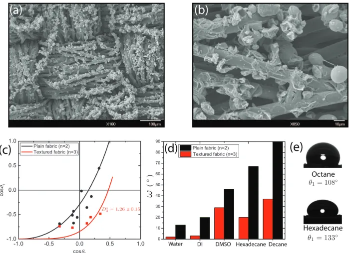
The spray-coated textured fabric exhibits an enhanced liquid-repellent behavior. In
Fig. 7c, we plot the cosine of the macroscopic contact angle cos θ1 against the cosine of
the equilibrium contact angle cos θE (analogous to Figure 3) for two samples Fabric E
that have either been dip-coated to increase the equilibrium contact angle on the fibers
θ2 → θE (black circles) or spray-coated to yield a third level of structure θ3 → θE (red
circles). The effect of introducing the third length scale is apparent in the larger values of the macroscopic contact angle on the sprayed-coated fabric for the various low sur-face tension liquids when compared to the dip-coated woven fabric. The differences in the roll-off angles between the spray-coated and dip-coated fabrics are shown in Figure
(a)
(b)
(d)
Hexadecane Octane ◦ = 133 1 θ ◦ = 108 1 θ 26 ± 0.15 . = 1 3∗ D(c)
ω
( ° )(e)
Water DI DMSO Hexadecane Decane
Figure 7: (a) Scanning Electron Micrograph (SEM) of a dip-coated nylon fabric (Fab-ric E) spray-coated with a 50/50 PMMA/fluorodecyl POSS solution to introduce a spherical microtexture on individual fibers; (b) Magnified SEM showing the spherical
PMMA/fluorodecyl POSS microtexture; (c) Plot of the effective contact angle (cos θ1)
against cos θE for the dip-coated plain weave fabric (black line) D∗1 = 1.7±0.29 and the
spray-coated fabric with D∗3 = 1.26±0.15 (red line); (d) A plot of the roll-off angle ω
(in degrees) on the dip-coated plain-woven fabric (black) and spray-coated textured
fab-ric (red) for a range of different liquids; (e) Liquid drops (V ≈ 10 µL) of hexadecane
(γlv = 27.8 mN/m) and octane (γlv = 21.6 mN/m) vertically deposited on the sprayed
7d. The textured spray-coated fabrics consistently show smaller roll-off angles for the range of liquids used, indicating a superior oleophobic character. In Figure 7e, we show liquid drops of octane and hexadecane that are deposited onto the spray-coated fabric
resulting in macroscopic contact angles of θ1 =108◦and θ1 =133◦, respectively. By
con-trast, the same sized drop of octane (V ≈10µL) completely wets the dip-coated fabric E.
The dimensionless spacing ratio of the weave was calculated previously (cf. Table 3) as
D∗1 =1.57±0.27 and is shown as the solid black line in Figure 7c. Using this value of D1∗,
which characterizes the geometry of the weave, we can perform a regression of the contact angle data on the spray coated fabric using eq 6a, 6b and 6c to obtain an estimate of the
mean spacing ratio of the spherical beads as D3∗ = 1.49±0.23. We also observe that the
transition to the Wenzel state on the spray-coated fabric occurs for n-heptane (γlv = 20.1
mN/m; θE =62◦). This best-fit estimate of D∗3 approximates the corrugated and
polydis-perse corpuscular beads with varied radii and interparticle spacing (as seen in Figure 7) as a model system of uniformly-spaced, hexagonally-packed array of spheres. By
apply-ing the simple model presented in the previous section usapply-ing this value of D∗3 ≈ 1.5, we
obtain an estimate of the maximum feature size that should be able to support a 1 mm
liq-uid drop of n-heptane as Rmin ≈ 100µm, which is an order of magnitude larger than the
5−15 µm structures observed in Figure 7b. However, the origin of this discrepancy can
be attributed to the broad distribution of the interparticle spacing in the real spray-coated fabric, and the metastability of the non-wetting Cassie-Baxter state. Local regions of the spray-coated fibers containing a low density of corpuscular spheres and large interbead spacing, act as nucleation sites for the Cassie-Baxter to Wenzel transition. Indeed, by
us-ing a value of R =10 µm for the corpuscular structures (consistent with SEM images), we
see that the 1 mm drop of n-heptane will locally wet regions where the value of D∗3 "4.7
(i.e., D3 = R(D∗3−1) ≈ 37 µm). An example of potential nucleation sites with large
in-terbead spacing can be seen in Figure 7b. Therefore, it is critical to develop processing techniques which can deposit a uniform and conformal layer of densely packed spherical
structures with minimal defect sizes. This will help prevent wetting transitions on oleo-phobic fabric surfaces, and allow for even lower surface tension liquids to be supported in the non-wetting state. Our simple spray-coating method clearly demonstrates the ben-efits of introducing a third re-entrant length scale when designing oleophobic fabrics, as revealed by the ability of the three-scale texture of Fabric E (shown in Fig. 7) to resist wetting by octane.
Conclusions
In this work, we initially performed a series of contact angle measurements on a set of
nine dip-coated omniphobic16 woven fabrics with varying yarn radius (R1) and
half-spacing (D∗2) using probe liquids of decreasing surface tensions (from water, γlv = 72.1
mN/m, to heptane, γlv = 20.1 mN/m). The trends of macroscopic apparent contact
angles and the transition to the fully-wetted Wenzel state are similar across all nine dip-coated woven fabrics despite the differences in weave construction. Fitting a modified version of the hierarchical two-level model outlined by Michielsen and Lee (2007) to the measured contact angle data allows us to obtain a single dimensionless geometrical
pa-rameter (D1∗) that characterizes the observed wetting behavior on each woven fabric. This
dimensionless parameter is related to the weave angle of the fabric, and can rationalize the experimentally measured trends in the apparent contact angles as well as the onset of a spontaneous wetting transition to the fully-wetted Wenzel state. For the particular case of tightly bundled fibers in the fabric yarns, our model further predicts the existence of
a critical value of the equilibrium contact angle of θE(c) ≈57◦, below which a liquid drop
will spontaneously transition to the fully wetted Wenzel state by a wicking mechanism. This is consistent with the observed transition data. We have demonstrated that the
in-troduction of an additional micro/nano-textured length scale on the fibers (n =3) is
rationalize this effect. We have extended previously developed ideas on pressure-driven Cassie-Baxter to Wenzel transitions in order to provide a framework that guides the selec-tion of particle size, feature density and surface coating at all three length scales. Finally, we provide an example of how introducing a spherical microtexture on the individual fibers using a spray-on technique can be used to extend the range of liquid repellency for a given fabric. The hierarchical equation set given by eq 6, in conjunction with the analysis of stability against meniscus depinning and sagging (eq 7-10), can be used to understand how to maximize the oleophobic character of a woven fabric system.
Acknowledgement
We gratefully acknowledge financial support from the Army Research Office through Contract W911NF-13-D-0001. We thank the Institute for Soldier Nanotechnologies (ISN) and the Center for Material Science and Engineering (CMSE) at MIT for the use of various analytic equipment.
Supporting Information Available
Scanning Electron Micrograph (SEM) images of each of the nine fabrics discussed in the text and wetting plots analogous to those shown in Fig. 3 for Fabrics A, D, E, F, and H. This material is available free of charge via the Internet at http://pubs.acs.org/.
References
(1) Tuteja, A.; Choi, W.; Ma, M.; Mabry, J. M.; Mazzella, S. A.; Rutledge, G. C.; McKin-ley, G. H.; Cohen, R. E. Designing Superoleophobic Surfaces. Science 2007, 318, 1618– 1622.
(2) Butt, H.-J.; Semprebon, C.; Papadopoulos, P.; Vollmer, D.; Brinkmann, M.; Cic-cotti, M. Design principles for superamphiphobic surfaces. Soft Matter 2013, 9, 418– 428.
(3) Marmur, A. Superhydrophobic and superhygrophobic surfaces: From understand-ing non-wettability to design considerations. Soft Matter 2013, 9, 7900–7904.
(4) Choi, W.; Tuteja, A.; Chhatre, S.; Mabry, J. M.; Cohen, R. E.; McKinley, G. H. Fabrics with Tunable Oleophobicity. Advanced Materials 2009, 21, 2190–2195.
(5) Kota, A. K.; Kwon, G.; Choi, W.; Mabry, J. M.; Tuteja, A. Hygro-responsive mem-branes for effective oil-water separation. Nature Communications 2012, 3, 1025.
(6) Gao, L.; McCarthy, T. J. Artificial Lotus Leaf Prepared Using a 1945 Patent and a Commercial Textile. Langmuir 2006, 22, 5998–6000.
(7) Ma, M.; Mao, Y.; Gupta, M.; Gleason, K. K.; Rutledge, G. C. Superhydrophobic Fab-rics Produced by Electrospinning and Chemical Vapor Deposition. Macromolecules
2005, 38, 9742–9748.
(8) Coclite, A. M.; Shi, Y.; Gleason, K. K. Grafted Crystalline Poly-Perfluoroacrylate Structures for Superhydrophobic and Oleophobic Functional Coatings. Advanced Materials 2012, 24, 4534–4539.
(9) Zimmermann, J.; Reifler, F. A.; Fortunato, G.; Gerhardt, L.-C.; Seeger, S. A Simple, One-Step Approach to Durable and Robust Superhydrophobic Textiles. Advanced Functional Materials 2008, 18, 3662–3669.
(10) Vilˇcnik, A.; Jerman, I.; ˇSurca Vuk, A.; Koˇzelj, M.; Orel, B.; Tomˇsiˇc, B.; Simonˇciˇc, B.; Kovaˇc, J. Structural Properties and Antibacterial Effects of Hydrophobic and Oleo-phobic Sol-Gel Coatings for Cotton Fabrics. Langmuir 2009, 25, 5869–5880.
(11) Deng, B.; Cai, R.; Yu, Y.; Jiang, H.; Wang, C.; Li, J.; Li, L.; Yu, M.; Li, J.; Xie, L.; Huang, Q.; Fan, C. Laundering Durability of Superhydrophobic Cotton Fabric. Ad-vanced Materials 2010, 22, 5473–5477.
(12) Miao, H.; Bao, F.; Cheng, L.; Shi, W. Cotton fabric modification for imparting high water and oil repellency using perfluoroalkyl phosphate acrylate via γ-ray-induced grafting. Radiation Physics and Chemistry 2010, 79, 786–790.
(13) Hayn, R. A.; Owens, J. R.; Boyer, S. A.; McDonald, R. S.; Lee, H. J. Preparation of highly hydrophobic and oleophobic textile surfaces using microwave-promoted silane coupling. Journal of Materials Science 2011, 46, 2503–2509.
(14) Zhang, J.; Seeger, S. Superoleophobic Coatings with Ultralow Sliding Angles Based on Silicone Nanofilaments. Angewandte Chemie International Edition 2011, 50, 6652– 6656.
(15) Lee, H.; Owens, J. In Advances in Modern Woven Fabrics Technology; Vassiliadis, S., Ed.; InTech, 2011.
(16) Tuteja, A.; Choi, W.; Mabry, J. M.; McKinley, G. H.; Cohen, R. E. Robust omniphobic surfaces. Proceedings of the National Academy of Sciences 2008, 105, 18200–18205. (17) Deng, T.; Varanasi, K. K.; Hsu, M.; Bhate, N.; Keimel, C.; Stein, J.; Blohm, M.
Non-wetting of impinging droplets on textured surfaces. Applied Physics Letters 2009, 94, 133109.
(18) Koishi, T.; Yasuoka, K.; Fujikawa, S.; Ebisuzaki, T.; Zeng, X. C. Coexistence and tran-sition between Cassie and Wenzel state on pillared hydrophobic surface. Proceedings of the National Academy of Sciences 2009, 106, 8435–8440.
(19) Bird, J. C.; Dhiman, R.; Kwon, H.-M.; Varanasi, K. K. Reducing the contact time of a bouncing drop. Nature 2013, 503, 385–388.
(20) Michielsen, S.; Lee, H. J. Design of a Superhydrophobic Surface Using Woven Struc-tures. Langmuir 2007, 23, 6004–6010.
(21) Kawabata, S.; Niwa, M.; Kawai, H. 3—The Finite Deformation Theory of Plain Weave Fabrics Part I: The Biaxial-Deformation Theory. Journal of the Textile Institute 1973, 64, 21–46.
(22) Herminghaus, S. Roughness-induced non-wetting. Europhysics Letters 2000, 52, 165. (23) Paxson, A. T.; Varanasi, K. K. Self-similarity of contact line depinning from textured
surfaces. Nature Communications 2013, 4, 1492.
(24) Cassie, A. B. D.; Baxter, S. Wettability of porous surfaces. Transactions of the Faraday Society 1944, 40, 546–551.
(25) Cassie, A. B. D.; Baxter, S. Large Contact Angles of Plant and Animal Surfaces. Nature
1945, 155, 21–22.
(26) Qu´er´e, D. Wetting and Roughness. Annual Review of Materials Research 2008, 38, 71– 99.
(27) Marmur, A. Solid-Surface Characterization by Wetting. Annual Review of Materials Research 2009, 39, 473–489.
(28) Leng, B.; Shao, Z.; de With, G.; Ming, W. Superoleophobic Cotton Textiles. Langmuir
2009, 25, 2456–2460.
(29) Hoefnagels, H. F.; Wu, D.; de With, G.; Ming, W. Biomimetic Superhydrophobic and Highly Oleophobic Cotton Textiles. Langmuir 2007, 23, 13158–13163.
(30) Ramaratnam, K.; Iyer, S. K.; Kinnan, M. K.; Chumanov, G.; Brown, P. J.; Luzinov, I. Ultrahydrophobic Textiles Using Nanoparticles: Lotus Approach. Journal of Engi-neered Fibers and Fabrics 2008, 3, 1–14.
(31) Makowski, T.; Kowalczyk, D.; Fortuniak, W.; Jeziorska, D.; Brzezinski, S.; Tracz, A. Superhydrophobic properties of cotton woven fabrics with conducting 3D networks of multiwall carbon nanotubes, MWCNTs. Cellulose 2014, 21, 4659–4670.
(32) Shirgholami, M. A.; Khalil-Abad, M. S.; Khajavi, R.; Yazdanshenas, M. E. Fabrication of superhydrophobic polymethylsilsesquioxane nanostructures on cotton textiles by a solutionimmersion process. Journal of Colloid and Interface Science 2011, 359, 530–535. (33) Liu, Y.; Tang, J.; Wang, R.; Lu, H.; Li, L.; Kong, Y.; Qi, K.; Xin, J. H. Artificial lotus leaf structures from assembling carbon nanotubes and their applications in hydrophobic textiles. Journal of Materials Chemistry 2007, 17, 1071–1078.
(34) Schneider, C. A.; Rasband, W. S.; Eliceiri, K. W. NIH Image to ImageJ: 25 years of image analysis. Nature Methods 2012, 9, 671–675.
(35) Meuler, A. J.; Chhatre, S. S.; Nieves, A. R.; Mabry, J. M.; Cohen, R. E.; McKinley, G. H. Examination of wettability and surface energy in fluorodecyl POSS/polymer blends. Soft Matter 2011, 7, 10122–10134.
(36) Srinivasan, S.; Chhatre, S. S.; Mabry, J. M.; Cohen, R. E.; McKinley, G. H. Solution spraying of poly(methyl methacrylate) blends to fabricate microtextured, superoleo-phobic surfaces. Polymer 2011, 52, 3209–3218.
(37) Bormashenko, E.; Gendelman, O.; Whyman, G. Superhydrophobicity of Lotus Leaves versus Birds Wings: Different Physical Mechanisms Leading to Similar Phe-nomena. Langmuir 2012, 28, 14992–14997.
(38) Srinivasan, S.; Chhatre, S. S.; Guardado, J. O.; Park, K.-C.; Parker, A. R.; Rubner, M. F.; McKinley, G. H.; Cohen, R. E. Quantification of feather structure, wettability and resistance to liquid penetration. Journal of The Royal Society Interface 2014, 11.
(39) Chhatre, S. S.; Choi, W.; Tuteja, A.; Park, K.-C. K.; Mabry, J. M.; McKinley, G. H.; Cohen, R. E. Scale Dependence of Omniphobic Mesh Surfaces. Langmuir 2010, 26, 4027–4035.
(40) Srinivasan, S.; Choi, W.; Park, K.-C.; Chhatre, S. S.; Cohen, R. E.; McKinley, G. H. Drag reduction for viscous laminar flow on spray-coated non-wetting surfaces. Soft Matter 2013, 9, 5691–5702.
(41) Yarnold, G. D. The hysteresis of the angle of contact of mercury. Proceedings of the Physical Society 1946, 58, 120–125.