---3I-F~I~-C EEBi=P~E~LPIIIIIIII I II _ III i y5y
Computational Modeling of Expanding Plasma Plumes
in Vacuum and in a Tank
by
Bernard K. Asare
Submitted to the Department of Aeronautics and
Astro-nautics in partial fulfillment of the requirements for the
degree of
Master of Science
at the
MASSACHUSETTS INSTITUTE OF TECHNOLOGY
September 1999
© Massachusetts Institute of Technology, 1999. All Rights Reserved.
Author ...
. ... ... ... ... ...Department of Aeronautics and Astronautics
15th September, 1999
C ertified by ... ...
...
Professor Manuel Martinez-Sanchez
Department of Aeronautics and Astronautics
Thesis Supervisor
A ccepted by ... .... ...
Nesbitt Hagood
Chairman, Departmental Committee on Graduate Studies
Department of Aeronautics and Astronautics
MASSACHUSETTS INSTITUTE
OF TECHNOLOGY
DEC
2 8 1999
Computational Modeling of Expanding Plasma Plumes in Vacuum and
in a Tank
by
Bernard K. Asare
Submitted to the Department of Aeronautical and Astronautical Engineering on September 15th, 1999, in partial fulfillment of the
requirements for the degree of Master of Science in Engineering
Abstract
Electric propulsion devices have shown to offer substantial fuel savings for various space missions. Hall thrusters, specifically, have shown great promise over the years due to their near optimum specific impulse for a number of space missions. The Hall thruster, how-ever, releases a partially ionized plasma plume which contaminates any surface it comes into contact with. Backflow contamination can lead to sputtering and effluent deposition on critical spacecraft components. A computational method for studying these interactions was developed by David Oh in 1997. He developed a Particle-in-Cell and Direct Simula-tion Monte Carlo (PIC-DSMC) algorithm to model the expansion of a plasma plume from a Hall thruster into a vacuum. In his work he implemented a plasma-surface interaction model which determined erosion rates on surfaces made of quartz, silicon and silver but he did not track the surface material removed.
In this work Oh's model is expanded to include the removal and tracking of material from generic spacecraft surfaces and the walls of a vacuum tank. Sputtering yields adopted in this model are based on sputtering theory developed by Matsunami and Yamamura. Since the plasma can have a negative impact on spacecraft subcomponents, a method for protect-ing the spacecraft (in the form of a protective shield) is proposed, studied, and recommen-dations are discussed.
Thesis Supervisor: Manuel Martinez-Sanchez Title: Professor
Acknowledgments
Thank you, Prof. M. Martinez-Sanchez, for your continuous support and inspiration throughout my graduate career at MIT. I will forever be indebted to you for what you call your 'preaching' sessions. Your words will always serve as a beacon in life ahead.
I would also like to express my gratitude to Omprakash Gnawali, an undergraduate student in the Electrical Engineering and Computer Science department at MIT, who I have worked with on the extension of the simulation and implementation of my ideas. We spent many hours together during which he and I refined the technical details of sputtering parameters and carried out endless tests and observations. Om_p, thank you.
Life at MIT would not have been complete and so much fun were it not for the good friends I made while pursuing my dream of becoming an aerospace engineer. I thank all, for your support at all times and I am looking forward to the day that our paths cross again.
Finally, I would like to extend my deepest gratitude to SharonLeah Brown and Marga-ret "Peggy" Edwards for their, advice, encouragement, and support throughout my career at MIT. Your kind hearts and your smiles will always make my day bright and happy.
This work was sponsored by the Air Force Office of Scientific Research under contract number F49620-98-1-0014.
Contents
1 Introduction
1.1 Background ... 1.2 M otivation ... ... 5 ... ... .. ... ... .. .. .... ..... 61.3 Issues with Vacuum Tank Experiments ... 1.4 Outline of Research ...
2 Closed-Drift Thrusters
2.1 Hall Thruster History ... 2.2 Plasmas ... 2.3 Hall Thruster Research at MIT ... 2.4 Hall Thruster Plume Research Outside MIT 2.4.1 Computational ... 2.4.2 Experimental ... 2.5 Thruster Basics ...3 The Sputtering Process
3.1 Introduction ... 3.2 The Sputtering Yield ... 3.3 Empirical Formulas for Sputtering ... 3.3.1 Matsunami's Empirical Formulation 3.3.2 Yamamura's Empirical Formulation 1 3.4 Angular Distribution of Sputtered Material 3.5 3.6 3.7 Angular S 3.4.1 The Sputtering Process -Computational Modeling The Sputtering Process -Experimental Work ... Xenon Ion Sputtering of Metals ... Sputtering Yield for Aluminum, Silicon, Iron, Silver and 4 3.7.1 Sputtering Yield vs. Incident Energy ... lependence Gold ... 3.7.2 Sputtering Yield vs. Incidence Angle4 Computational Model
4.1 Introduction ... 4.2 The Background Environment ... 4.3 Modeling The Hall Thruster Exit Plane .... 4.4 Modeling The Plume ... 4.4.1 Collisions ... 4.5 Modeling the Surface Interactions ... 4.6 The Tank Geometry ... 4.7 The Spacecraft Geometry ...5
Results
5.1 Introduction ... . ... 25 ... 25 ... 27 ... 27 of Yield 31 ... 34 ... 35 ... 37 ... 38 ... 38 ... .39 ... 42 .45 .46 .47 .50 .51 .52 .54 .54 .57 ...5.2 The Tank Simulation ...
5.2.1 Species Distribution in Hall Thruster Plume 5.3 Simulation of the Effects of a Plume Shield ... 5.4 The Effect of Protective Shields ...
5.5 Deposition of Shield Material on Solar Array .... 5.6 Plume Structure ...
5.7 Key Ion-Related Distributions on Solar Array .... 5.8 Neutral (Xe) Flux Distribution on Array ... 5.9 Neutral (Xe) Impact Energy Distribution on Array 5.10 Erosion Rates of Solar Array and Shield Wall ... 5.11 Deposition of Aluminum on Solar Array ... 5.12 Collimating Effect of Shield Visualized ... 5.13 Deposition of Shield Material on Solar Array ... 5.14 Summ ary ...
6 Conclusion
6.1 Results ...
6.2 Recommendations for Future Work ...
... 58 ... 58 ... 64 ... 65 ... 67 ... 68 ... 69 ... 8 1 ... 83 ... 85 ... 86 ... 88 ... 90 . ... 93
List of Figures
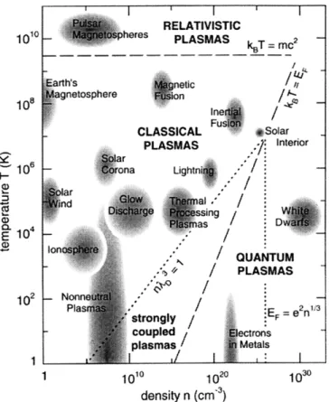
Plasmas occurring naturally or created in the laboratory as a function of density (# / cm3) and
temperature (in kelvin) ... 13
Cross-section of a typical Hall Thruster ... ... 19
The SPT-100 ... .. . ... 21
The TAL-55 ... . .... ... ... 21
Hall Thruster - SPT-100 ... ... 22
Hall Thruster Plume Cross-Section ... ... 22
Schematic of Sputtering Geometry ... ... 28
Coverglass sputtering yield vs. Incidence Angle for Xenon Ions at 300eV ... 40
Sputtering Yield vs. Incident Energy - Argon Comparison ... 41
Sputtering Yield vs. Incident Energy -Xenon Comparison ... 41
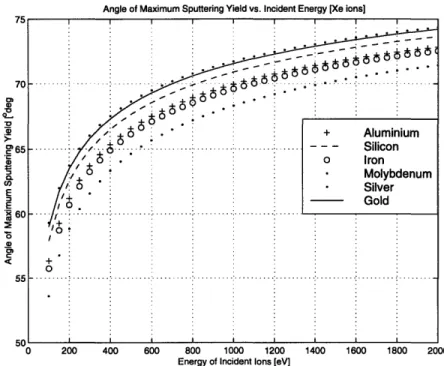
Angle of Maximum Sputtering Yield vs. Impinging Ion Incident Energy ... 43
Maximum Sputtering Yield vs. Impinging Ion Incident Energy ... 43
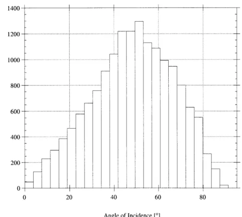
Distribution of Angle of Incidence on all Spacecraft Surfaces -Primarily Solar Array ... 44
Cross Section of SPT-100 Model ... 48
Experimental Measurements of Near Field Current Density [Absalamov, 1992 and Gavryushin, 1981] ... 48
Comparison of Fife and Gavryushin Ion Current Distribution 4mm from Thruster Exit [Qarnain, 1998] ... ... 49
Comparison of Fife and Gavryushin beam Divergence Angle Distributions 4mm from Thruster Exit [Qarnain, 1998] ... 49
Cumulative Distribution Function for Ion Current Density ... 50
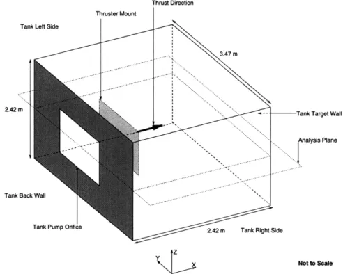
Vacuum Tank Configuration. Includes Thrust Stand and Pumping Orifice ... 54
Spacecraft Baseline Configuration. Includes Bus, Solar Array and Protective Shields ... 55
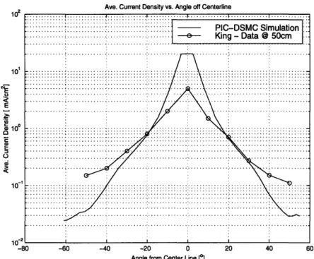
Current Density Distribution 1 m from Thruster Exit Plane Compared to King's Data. ... 59
Neutral Density in Plane Dissecting Tank [approx. 5.5 x 10¹⁶ m-3] after 10,000 Iterations .. .. 60
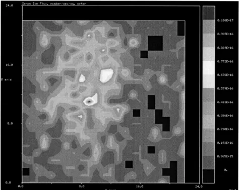
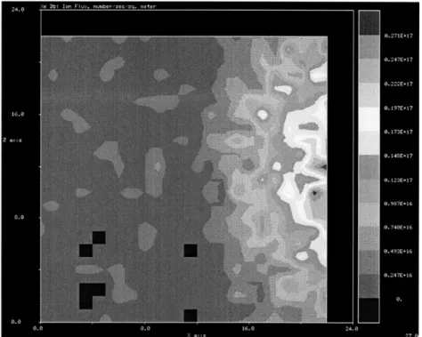
Xenon Neutral Flux on Top Wall of Tank ... Xenon Neutral Flux on Bottom Wall of Tank ... Xenon Ion (Xe+) Flux on Left Wall of Tank ... Xenon Ion (Xe++) Flux on Left Wall of Tank ... Total Particle Count vs. Iteration Number ... Sketch Showing Important Dimensions Used in Shield Study .... Current Density on Solar Array -Shield Length = 0.00 m ... Current Density on Solar Array -Shield Length = 0.10 m ... Current Density on Solar Array -Shield Length = 0.20 m ... Current Density on Solar Array -Shield Length = 0.30 m ... Xe+ Flux Distribution on Solar Array - Shield Length = 0.00 m .. ... 6 1 ... 61 ... 62 ... 62 ... 63 ... ... .. ... 65 ... 69 ... 69 ... 70 ... 70 ...7 1
Xe+ Flux Distribution on Solar Array -Shield Length = 0.10 m ....
Xe+ Flux Distribution on Solar Array -Shield Length = 0.20 m .... Xe+ Flux Distribution on Solar Array -Shield Length = 0.30 m ...
Xe++ Flux Distribution on Solar Array -Shield Length = 0.00 m ...
Xe++ Flux Distribution on Solar Array -Shield Length = 0.10 m ... Xe++ Flux Distribution on Solar Array - Shield Length = 0.20 m ... Xe++ Flux Distribution on Solar Array - Shield Length = 0.30 m ...
Quartz Erosion Rate on Solar Array -Shield Length = 0.00 m ... Quartz Erosion Rate on Solar Array -Shield Length = 0.10 m ... Quartz Erosion Rate on Solar Array -Shield Length = 0.20 m ... Quartz Erosion Rate on Solar Array -Shield Length = 0.30 m ... Silicon Erosion Rate on Solar Array -Shield Length = 0.00 m ... Silicon Erosion Rate on Solar Array -Shield Length = 0.10 m ... Silicon Erosion Rate on Solar Array -Shield Length = 0.20 m ... Silicon Erosion Rate on Solar Array -Shield Length = 0.30 m ... Silver Erosion Rate on Solar Array - Shield Length = 0.00 m ... Silver Erosion Rate on Solar Array - Shield Length = 0.10 m ... Silver Erosion Rate on Solar Array - Shield Length = 0.20 m ... Silver Erosion Rate on Solar Array - Shield Length = 0.30 m ...
... .71 ... ... ... 72 ... ... .72 ... .... ... 7 3 ... .... .. ... 7 3 ... ... .... .... 74 ... 74 ... 75 ... .... ... 7 5 ... 76 ... 76 ... ... 77 ... 77 ... ... 7 8 ... ... 7 8 ... ... 7 9 ... 79 ... 80 ... 80 Xe Neutral Flux Distribution (x10 17) on Solar Array -Shield Length = 0.00 m ...
Xe Neutral Flux Distribution (x10 17) on Solar Array -Shield Length = 0.10 m ... Xe Neutral Flux Distribution (x10 16) on Solar Array -Shield Length = 0.20 m ... Xe Neutral Energy Distribution on Solar Array -Shield Length = 0.00 m ... Xe Neutral Energy Distribution on Solar Array -Shield Length = 0.10 m ... Xe Neutral Energy Distribution on Solar Array -Shield Length = 0.20 m ... Erosion Rate for Silver, Silicon and Quartz on Solar Array vs. Shield Length ... Erosion Rates on Left Wall of Shield ... ... ... Aluminum Deposition Distribution (x10 16) on Solar Array -Shield Length = 0.10 m ... Aluminum Deposition Distribution (x10 16) on Solar Array -Shield Length = 0.20 m ... Aluminum Deposition Distribution (x1016) on Solar Array - Shield Length = 0.30 m ... Plume Particle Distribution Without Protective Shield ...
Plume Particle Distribution - Shield Length = 0.10 m ... Plume Particle Distribution -Shield Length = 0.20 m ... Plume Particle Distribution - Shield Length = 0.30 m ... Aluminum Deposition on Solar Array -Shield Length = 0.10 m ... Aluminum Deposition on Solar Array -Shield Length = 0.20 m ... Aluminum Deposition on Solar Array -Shield Length = 0.30 m ...
81 81 82 83 83 84 85 85 86 86 87 88 88 89 89 90 91 92
Chapter 1
Introduction
1.1 Background
For satellite or deep-space missions utilizing chemical propulsion, a large percentage of the spacecraft wet mass is propellant. Due to vehicle mass and cost design constraints, this excessive amount of propellant decreases the mass available for payload. In some cases, this decrease in payload mass is so extreme that the mission is no longer feasible within the design space.
Studies have shown that for many missions, an engine which would be used as the pri-mary source of propulsion for orbit transfer missions or for satellite station-keeping should produce exhaust velocities between 10-20 km/s. Cryogenic chemical rocket sys-tems are capable of producing exhaust velocities approaching 5 km/s and storable chemi-cal systems that are currently in use for spacecraft propulsion have significantly lower performance still. It is apparent that a propulsion system is required that does not rely on energy addition through chemical reactions.
Electric Propulsion (EP) thrusters are such a design enabling technology, producing exhaust velocities on the order of 10-20 km/s. This significantly decreases propellant mass and typically enables a higher payload mass. The drawbacks of EP are small values of thrust and a large power supply mass. In some cases, the mass of the power supply offsets the gains of choosing EP over chemical systems. However, recent advances in both EP and power supply technology are making these systems viable options for energetic deep-space missions (e.g. Deep Space 1), attitude control, and near-Earth orbit raising missions just to name a few.
1.2 Motivation
With renewed interest in electric propulsion for a number of planned missions, as well as station keeping applications for geostationary communications satellites, the important issues of spacecraft contamination are receiving increased attention. For example, in Hall thruster (HT) plumes, an energetic plasma is created by charge-exchange processes, and can expand around a spacecraft leading to a current drain on high voltage surfaces. The enhanced plasma density can also lead to attenuation and refraction of electromagnetic wave transmission and reception. In addition, many thrusters emit heavy metal species, both charged and uncharged, due to erosion which can easily adhere to spacecraft sur-faces. It is vitally important to understand and predict the backflow transport of these spe-cies from the plume onto a spacecraft. Thus, a clear understanding of the plumes of EP thrusters and the transport of contaminating effluents in them is necessary. Backflow con-tamination can lead to sputtering and effluent deposition that can affect such aspects of the spacecraft as solar arrays, thermal control surfaces, optical sensors, communications, sci-ence instrumentation, general structural properties of materials, and spacecraft charging.
Of particular concern are the charge exchange (CEX) ions created when electrons are
transferred from slow moving neutrals to fast moving ions during a collision. Slower mov-ing ions and fast movmov-ing neutrals are created in the process. It is these CEX ions -energies of 0eV to 400eV - which interact with the surfaces of the spacecraft. This has resulted in an increase in the number of laboratory studies and modeling efforts which have success-fully identified the dominant mechanisms for plume-spacecraft interactions, and have ade-quately quantified a number of them. Among the effects now known with adequate precision, or for which data can be confidently obtained in ground-based facilities include the:
* angular dependence and energy spectrum of the main plume * distortion of microwave beams crossing the plume
* general features of the production of low-energy ions by CEX collisions in the near plume
* thermal radiation from plumes
per-formance
Even though many of the above measurements have been performed, uncertainties still persist in a few areas, where the effects of test facilities are difficult to eliminate com-pletely. These uncertainties include:
* re-deposition of sputtered material from tank walls, and its masking effect on the plume erosion or deposition of thruster-originated material
* possible effects of the 're-circulating' background plasma commonly found in vacuum tanks during thruster operation, which tends to be confused with CEX plasma
* potential effects of ingestion of residual neutral tank gas through the thruster exhaust. (even though the effect on thrust may be measurable, questions remain about effects on thruster wall erosion and plume structure by ions formed from the ingested gas)
* long-distance evolution of the plasma plume, under the influence of the ambient geomagnetic field
* refined and extended modeling of ion-wall interactions, covering most of the materials of interest to spacecraft
* alleviation measures, such as the use of plume shields
This work addressed the possible 're-circulation' of plasma as well as the re-deposi-tion of tank wall material during thruster operare-deposi-tion and the effects of a plume shield, as these are deemed to be the effects most seriously affecting projections on spacecraft and environmental quality.
Since it is believed that CEX ions are primarily responsible for damaging spacecraft subsystems exposed to the plasma, simulations involving a protective shield which sur-rounds the exit of the thruster were performed. The purpose of these tests was to verify if shields do protect spacecraft subcomponents from the damaging CEX ions, and whether redeposition of sputtered shield material may itself become an issue.
1.3 Issues with Vacuum Tank Experiments
Collimators have been used to prevent sputtering contamination of surfaces from test chamber walls. They are to some extent effective, but they also introduce measurement uncertainties by restricting the access of engine debris which would otherwise deposit from some angles and also by generating their own sputtering fluxes.
Knowledge of the structure, potential and composition of the plasma induced by the thrusters at angles far from the plume axis is important for assessment of current closure, optical contamination of sensitive science sensors, and possibly sputtering by low-energy plasma. Because of the possible return of some fraction of the beam ions, together with secondary, wall-generated ions, from the beam stopping surface, this information is diffi-cult to obtain from tank experiments.
Techniques such as mass and emission spectroscopy and laser-induced fluorescence are used to obtain species-specific information. This information includes particle veloci-ties, flux, temperature, density and angular distribution. These experiments are not only complicated to perform but are also expensive to set up. It is, however, important to under-stand the interactions of electric propulsion subsystems with the rest of the space craft.
1.4 Outline of Research
The broad goal of this work is to gain insight into the contamination process, and to accurately provide estimates of contaminating fluxes so that spacecraft designers can inte-grate EP devices on spacecraft with a much higher level of confidence. Since it is believed that CEX ions from EP devices are primarily responsible for damaging spacecraft sub-systems exposed to the plasma, and Oh's algorithm did not include a detailed study of plasma-surface interactions, the goals of this work are as follows:
* To improve modeling and computation of sputtering yields material commonly used in spacecraft design
* To upgrade Oh's model to include tracking of material sputtered off of surfaces * To compute plasma properties inside a tank, far from the thrust axis.
* To study the trade-offs involved in using plume shields to protect spacecraft sub-components from the damaging effects of the plume.
In the following chapters, the background and history of Hall thruster as well as the theory underlying the sputtering process is explained. This is followed by a description of the algorithms, computer code and the assumptions made in the plume model employed for the simulations. The results of vacuum tank simulations are discussed and compared to experimental data. Next, the preliminary results for a generic spacecraft employing a pro-tective shield mounted around the thruster exit are presented. The purpose of these tests is to verify if shields do protect spacecraft subcomponents from the damaging CEX ions, and verify if redeposition of sputtered shield material may itself become an issue. Finally the conclusions of this work are presented and recommendations for future work are sug-gested.
Chapter 2
Closed-Drift Thrusters
2.1 Hall Thruster History
Hall Effect Thrusters (HET) have an extensive flight history on-board Russian space-craft for stationkeeping, attitude control, orbit injection and repositioning applications. They have been used on at least 23 spacecraft since 1971. The SPT-100 (Stationary Plasma Thruster - 100) has flown on at least three Russian satellites and has completed qualification for Western commercial satellite applications. The SPT-100 HET was sched-uled to provide NSSK on a French satellite in 1999 and is planned for use on future Space Systems/Loral satellites whereas the D-55 Thruster with Anode Layer (TAL) HET flew on an experimental BMDO mission in 1997.
SPTs have generated a lot of interest in recent years because of their high efficiency, ideal Isp values, reasonable thrust levels, and their excellent flight experience over the last 25 years. International Space Technology, Inc. (ISTI) is the joint venture formed by Space Systems/Loral, Fakel Enterprises (Russia), the Research Institute of Applied Mechanics and Electrodynamics of the Moscow Aviation Institute (MAI/Russia), and its other inter-national partners to commercialize SPTs for use on Western spacecraft. The U.S. Ballistic Missile Defense Organization has aggressively pursued the development of SPTs for Bril-liant Eyes-class missions through its multi-phased Russian Hall Effect Thruster Technol-ogy (RHETT) program.
With the increasing emphasis on lowering the mass of spacecraft propulsion systems, increasing spacecraft orbiting lifetimes, and reducing overall costs, together with greater
amounts of electric power now available on-board spacecraft, the applications for electric propulsion systems will certainly continue to grow.
Thus after a long period of laboratory maturation, both in the former Soviet Union and in the West, HET technology has matured to a point where its expanded use for select space missions is justified from both a technological and an economic standpoint. One remaining area, however, where some reluctance to its adoption needs to be overcome is the possibility of damaging interactions of the energetic plumes of these thrusters with
solar arrays, optical sensors and other space craft surfaces / subsystems.
2.2
Plasmas
Plasma science is the study of the ionized states of matter. Plasmas occur quite naturally whenever ordinary matter is heated to a temperature greater than about 10,0000 C. The resulting plasmas are electrically charged gases or fluids. They are profoundly influenced by the long-range Coulomb interactions of the ions and electrons and by the presence of magnetic fields, either applied externally or generated by current flows within the plasma. The dynamics of such systems are complex, and understanding them requires new con-cepts and techniques.
Plasma science impacts daily life in many significant ways. Low-temperature plasmas, in which electric fields in the plasma can impart significant energy to the electrons and ions but the plasmas are still cool enough to support a multitude of chemical reactions, are critical to the processing of many modem materials. This method of "plasma processing" is an enabling technology in the fabrication of semiconductors. Important applications include the plasma etching of semiconductors and the surface modification and growth of new materials. Other important uses of low-temperature plasmas include the "cold" pas-teurization of foods, the sterilization of medical products, environmental cleanup, gas dis-charges for lighting and lasers, isotope separation, switching and welding technology, and plasma-based space propulsion systems. As illustrated in the Figure 2. below, plasmas occur in many contexts, spanning an incredible range of plasma densities and tempera-tures.
1010
108 I " /"
CLASSICAL SFu Solar
PLASMAS .. Interior I, l na Lghtni .2 I QUANTUM ./ / PLASMAS strongly
/
= e n coupled s Splasmas Metals lasma i Me t a 1 010o 102 103" density n (cm 3)Figure 2.1 Plasmas that occur naturally or can be created in the laboratory are shown as a function of density (in particles per cubic centimeter) and temperature (in kelvin).
2.3 Hall Thruster Research at MIT
Extensive work, pertaining to Hall Thruster modeling, has been done at MIT to date. Lentz, in 1993, developed a quasi-one-dimensional model which predicted plasma quanti-ties and thruster performance along the acceleration channel. It was shown that this model matched experimental data quite well by comparing it to research results from a Japanese Hall Thruster.
While Lentz concentrated on developing the one-dimensional model, Oh was develop-ing a two dimensional and three-dimensional model which studied expanddevelop-ing plasma plumes in space. His work implemented a combined Particle-in-Cell (PIC) and Direct Simulation Monte Carlo (DSMC) method to create a quasi-neutral PIC-DSMC model
which not only described the expansion of the partially ionized plasma but also included a crude model of its interaction with (satellite) surfaces.
In 1998, Qarnain expanded on Oh's work by modifying the surface interaction model and looked at the issues associated with developing and end-to-end model of the Hall Thruster. The current work further modifies Oh's work to include the effect of material sputtered from surfaces (tank or spacecraft) back into the plasma and includes a study of the effects of shields on expanding plasmas.
In 1995, Fife developed a two-dimensional hybrid-PIC model based on Lentz's one dimensional by extending it radially in the accelerating channel. This model, unlike Lentz's model is designed to use a thruster's geometry as one of its inputs. Theoretically this model can be used to simulate an expanding plasma of any thruster, however, most tests were validated against an SPT-100 [Bishaev and Kim, 1978]. Fife's model was vali-dated by an extensive set of electrostatic probe measurements in the plume. The model also studied low-frequency discharge oscillations, energy distribution of ions ejected from the thruster, the interaction of the thruster walls with the plasma, and the effect of facility background pressure on efficiency.
Ahedo and Martinez-Sanchez developed a one-dimensional model of the SPT provid-ing a well defined set of governprovid-ing equations for the plasma dynamics. This model, how-ever, was focussed on the steady state plasma characteristics and did not include the discharge oscillation observed in many SPTs. Noguchi, in 1999, developed a model based on linear perturbation of the steady state variable derived by Ahedo and Martinez-Sanchez, in order to study the transient, oscillatory characteristics of an operating SPT. Noguchi's model predicted two families of modes, one basically acoustic, the other due to ionization dynamics. The modes, however, were of a higher frequency than those observed in real thruster operation.
Experimental work at MIT has been centered around developing, testing and charac-terizing a 50 Watt Hall Thruster. More about this work can be read in Khayms' Masters thesis [Khayms, 1997].
2.4 Hall Thruster Plume Research Outside MIT
2.4.1 Computational
Although it is often not readily apparent, plasma science affects our society in a myr-iad of ways and as a result computational modeling of plasma-based phenomena has been extensive. Techniques currently used in modeling and simulating plasma flows by the sci-entific community include the following methods:
* Molecular Dynamics method * Particle-in-Cell method
* Particle-in-Cell with Monte Carlo Collisions method * Direct Simulation Monte Carlo method
These methods have been fully developed and thus will not be reviewed here. For their detailed description, their merits and disadvantages, refer to Birdsall and Langdon [1991] and Lubachevsky [1991]. It should be noted that Oh used a combination of the PIC and
DSMC methods in developing his model [Oh, 1997].
With respect to modeling Hall Thruster plumes in academia, Randolph and Pencil con-structed an empirical plume model in order to predict contamination on surfaces exposed to the plume of an SPT-100 [Randolph et al., 1994 and Pencil et al., 1996]. In this model they assumed a Gaussian distribution for the current density at the thruster exit plane and they developed a sputtering model which included the energy and angular dependence of
sputtering.
Bishaev et al. [1993] developed a kinetic model of the plume but the formulation is quite complex (based on a solution of a set of Boltzmann equations) and limited to simple geometries.
In 1995, Rhee and Lewis developed a hybrid PIC model of the SPT plume which was similar to that developed by Samanta Roy [1995] to model plumes from ion thrusters. It combined a PIC algorithm for the CEX ions and an analytical model for the ion beam. This model, however, is deemed to be flawed [Oh, 1997] as Rhee and Lewis use particles to model the difference between ion and electron charge densities.
A substantial amount of work has been done by VanGilder and Keidar in modeling EP devices. In their latest paper [VanGilder, Keidar, and Boyd, 1999] a very similar algorithm to Oh's is described. The difference is that Oh's model assumed a constant electron tem-perature whereas VanGilder et al. developed two cases - one assuming isothermal elec-trons, and one assuming a variable electron temperature. They observed that the model including a variable electron temperature showed better agreement with experimental results.
In summary, even though numerous models have been developed to describe expand-ing plasma plumes of EP devices, with the increased interest in employexpand-ing HT devices in space missions, it is becoming apparent that fully understanding the impact of the plume in the on spacecraft subsystems is critical in the design process.
2.4.2 Experimental
Numerous research efforts in the former Soviet Union have focused on studying Hall Thruster physics since their development in the 1960s. Recognizing the numerous advan-tages of HTs, more and more research is being conducted in the U.S., with the hope of commercializing HT systems. Soviet researchers have done extensive developmental work on hall thrusters but it was not until the early 1990s that results began appearing in the West. Absalamov et al. were the first to publish results on far field plume data. These included ion distribution and witness plate measurements of erosion rates on solar cell cover glass 1 meter away from the thruster exit plane.
In the U.S., Myers and Manzella [1993] performed a set of experiments to validate and extend the Russian work. They mapped out the electron density, electron temperature and ion current density in the plume up to 4 meters away from the exit plane. In 1993 Manzella measured the neutral/ion distribution and the emission spectrum at the exit plane of an SPT-100. It was found that the plume consisted of 1-5% xenon neutrals (Xe), 76% - 89% singly charged ions (Xe+), and 11.9% - 19% doubly charged ions (Xe++). He also showed that the facility background pressure had an effect on the ion density in the backflow region of the plume. In a more recent study, King [1998] found a comparable distribution of particles (Xe+= 88.8%, Xe+ += 11%, Xe+ + + = 0.2%). King's study was also the first
ever documentation of the existence of triply charged xenon ions in the Hall Thruster plume.
Since the impact of HT plumes on other spacecraft sub-systems has always been a pri-mary concern, several experiments have been conducted by Absalamov et al. and Pencil where samples of cover glasses and interconnect material are exposed to the plume at var-ious angles and distances. In some of these experiments collimators were used to protect the samples from the material sputtered from the wall of the vacuum tank. In experiments without collimators it was seen that samples near the center-line of the beam had a net ero-sion whereas samples farther than 600 off the thrust line showed a net deposition of mate-rial. The source of this material, however, was the tank walls and not the thruster channel. Randolph et al. and Pencil et al. [1994] also performed experiments without collimators
and these showed no net deposition on the samples.
Researchers at the University of Michigan have also provided comprehensive data. This data includes:
* ion fluxes, neutral fluxes, heat flux, and ion energy distribution [King, 1996] * near field measurements of charge and ion density [Kim, 1996]
* plasma density in the plume [Ohler et al., 1995]
* phase shift measurements and L-Band attenuation [Ohler et al., 1996]
Since Hall thrusters are efficient, have a high Isp, and are relatively easy to operate, many companies are interested in implementing these devices in their space missions. This interest has sparked the large number of ground tests described above. It must be noted, however, that no space-based data is currently available though efforts are being made to design and carry out such experiments.
2.5
Thruster Basics
A closed-drift thruster is defined as a thruster in which ions are electrostatically acceler-ated in the primary thrust direction, with the accelerating electric field established by an electron current interacting with a transverse magnetic field. Figure 2.2 shows a schematic of a cylindrically symmetric design. A radial magnetic field is developed between two axi-ally symmetric magnet pole pieces as shown. The interior volume surrounded by the
mag-net is continually filled with a low pressure propellant gas that supports an electric discharge between two electrodes. Xenon is the preferred fluid for this operation, because it has high atomic mass combined with a low ionization potential.
The anode electrode is located upstream, while the cathode electrode is located in the region directly downstream of the magnet pole pieces. The axial electrostatic field created between the anode and cathode steers some of the electrons toward the annular channel where they collide with and ionize the xenon atoms. Under the effect of the electrostatic field the ions are pushed toward the engine outlet (exit plane) at a high-speed, thus gener-ating the thrust. In order to ensure that the ions are accelerated in a single direction, the ion cyclotron radius must be far greater than the acceleration channel length. The effect of a magnetic field generated by the peripheral coils is used to increase the probability of an electron and atom collision in the annular channel and to focus the ion beam at engine out-let. The unused electrons can neutralize the ions after they have been ejected from the engine, thereby preventing the entire propulsion system from accumulating electrical charge.
The axial electric field also interacts with the radial magnetic field to generate the Hall current in the azimuthal direction. The unique feature, however, of this device is that the major current flow is the Hall current perpendicular to the electric field, hence the name Hall accelerator or Hall thruster.
This device is particularly suited for missions requiring a specific impulses in the range of 1000 to 2000 sec. Thrust levels in the 3mN to 2N range have been obtained. The overall thrust is determined by the size and power level of the device, but no obvious upper limit has been found. At the low power end, the plasma tends to become too dense and aggressive, limiting thruster life.
OUTER MAGNETIC
ELECTROMAGNETS JSED TO POLE
ESTABLISHMAGNETIC E LD S INNER MAGNETIC POLE ELECTRON SOURCE PROPELLANT /I INJECTION ELECTRONS TRAPPEDIN CROSSEDFIELDS ELECTRONSIMPAC IONS
ATOMSTO CREATE ELECTROSTATICALLY
IONS ACCELERATED
Figure 2.2 Cross-section of a typical Hall Thruster
A variety of different configurations of these thrusters have been developed in the
former Soviet Union and flown on several different spacecraft but there are primarily two types of designs. One device is constructed such that the channel walls are made of a dielectric material (e.g. Boron Nitride) and is referred to as a Stationary Plasma Thruster
(SPT) or closed-drift extended acceleration thruster. The other device is called the
'thruster with anode layer' (TAL). This differs from the SPT in that its acceleration chan-nel is relatively shorter and the side walls are made of a conductive material instead.
The Stationary Plasma Thruster, developed in the former Soviet Union by Morozov and manufactured by Fakel, is often used as a baseline for analyzing physical properties and performance. Many experimental and numerical tests have been performed in an attempt to better understand the physics of the accelerating process within the thruster, the expansion of the plasma in a vacuum as well as the effect of the plasma on various space-craft surface samples. The characteristics of the thruster used for purposes of this research are listed in Table 2.1 below
One issue associated with HT devices is that complete ionization cannot be achieved with reasonable levels of power, and hence, neutral gas is emitted at thermal speeds. These slow neutrals are of interest because they charge-exchange with the fast beam ions produc-ing fast neutrals and slow ions which can be influenced by local electric fields in the plume. The electric field structure in the plume, as seen in experiments and in computa-tional models, is radial, and hence the slow ions are pushed out of the beam and move back towards the spacecraft.
Parameter Numerical Value
Specific Impulse 1610 sec. Specific Impulse (w/o cathode) 1735 sec.
Thrust 84.9 mN
Discharge Voltage 300 V
Discharge Current 4.5 A
Power 1350 Watts
Efficiency 49.7%
Efficiency (w/o cathode) 53.5%
Inner Insulator Diameter 56 mm
Outer Insulator Diameter 100 mm
Propellant Xenon
Propellant Flow Rate 5.37 mg. / sec.
Fraction of Propellant Directed 5%- 10%
to Cathode 7.1% is assumed in model
Electron Temperature in Plume 2 -4 eV Axial Ion Velocity -17,000 m/s
Fraction of Propellant Ionized in > 95% Discharge Chamber
Figure 2.3 The SPT-100
Figure 2.5 Hall Thruster -SPT-100
Chapter 3
The Sputtering Process
3.1 Introduction
Sputtering is the removal of surface atoms from a target material by bombarding the latter with energetic particles. It is commonly measured by the sputtering yield, which is the average number of atoms removed from the surface of the target per incident particle. Aside from sputtering other effects also take place when particles bombard surfaces. These include backscattering as well as trapping and reemission of incident particles, des-orption of surface layers, the emission of electrons, the emission of photons and a change in surface structure and topography of the target material. To date, many experiments involving sputtering of monoatomic targets (metals) with noble gases have been con-ducted, though more and more experiments including compounds and alloys are being performed. An excellent review of sputtering phenomena is provided by Behrisch et al. in Topics in Applied Physics series published by Springer-Verlag. A more recent review, focused on the low-energy end, was reported by Duchemin et al. [1997].
Sputtering used to be considered as the undesired effect taking place when cathodes were eroded and plasmas were contaminated but today, sputtering is widely applied to sur-face cleaning and etching, for thin film deposition, for sursur-face layer analysis and for sput-ter ion sources. However, sputsput-tering as pertaining to satellite design and integration, is still considered an undesired effect.
3.2 The Sputtering Yield
defined as the average number of atoms removed from the surface of a target material (solid) by each impinging ion. The incident particles can be ions, neutrals, electrons or energetic protons. In the case of an EP device where the impinging particles are usually monoatomic (e.g. xenon) ions each of the incident ions is counted separately. When count-ing the number of particles that have been removed from the surface of a material only those of the solid (target) are counted, while the incident particles which have been reflected or reemitted are not counted.
Sputtering yields for energetic particles (keV -MeV energy range) are usually in the range of 10-5 < Y < 103 atoms per incident particle but they depend on the following fac-tors:
* incident particle energy * incident particle mass
* incidence angle (the angle between the particle direction and the surface normal) * mass of the target atoms
* crystallinity and crystal orientation and surface topography of the target material * surface binding energy of the target material
It has been found that the yield is almost independent of the temperature and that there is a (material dependent) threshold energy (20eV - 100eV) below which no sputtering occurs. The sputtering yield usually increases with incident particle energy but peaks with a broad maximum of 5 -50 keV. At higher incident energies, the sputtering yield decreases since the impinging ions burrow deeper into the target material and are forced to shed their energy deep within the target material and further away from the surface layers.
It has been observed that when ions impinge on a target at oblique angles the sputter-ing yield tends to increase monotonically with incidence angle until a peak between 60 and 85 degrees. This peak is a function of the incident particle mass and energy as well as the surface structure of the target material. If the target material is a single crystal, sputter-ing is affected by the target crystal orientation with respect to the impsputter-ingsputter-ing angle. For example, the yields for particles impinging near the three major close-packed crystal axes are 2 to 5 times lower than for other angles of incidence. Also for the close-packed
direc-tions the maxima in the energy dependence of sputtering tends to be in a lower energy range.
There are three mechanisms by which particles are emitted form the surface of a bom-barded material. In the single-knockon regime the bombarding ion transfers energy to tar-get atoms which, after having undergone a number of collisions, are ejected through the target surface provided they have energy in excess of the binding energy of the target. It must be noted that the atoms from the ion-target collisions gain enough energy to get sput-tered, but not enough to generate recoil cascades -target atoms dislocated from their orig-inal lattice positions and undergoing more collisions. In the linear cascade regime the atoms resulting from the ion-target collisions gain sufficient energy to generate recoil cas-cades of which some may reach the surface of the target. The density of the recoil atoms, however, is low enough to ensure that knock-on collisions are dominant and collisions between moving atoms is infrequent. In the spike regime, on the other hand, the density of the recoil atoms is so high that most of the atoms within a given volume are in motion.
According to Behrisch et al. the charge states of the emitted particles is also important, though for sputtered metals a large fraction of the sputtered atoms emerge as neutrals in their ground states. Within the target material, however, dislocated atoms move towards the surface layer in an ionized or excited state. This indicates that the fundamental event in the excitation process involves the interaction of one emerging atom with the target sur-face. The probability of an atom being neutralized or ionized determines the state of the sputtered atom, though the initial state of the target atom is not significant as the probabil-ity of maintaining its charge state as it traverses the target material to the surface is very small at typical energies of sputtered atoms (-l10eV). Since a large fraction of the sput-tered atoms emerge as neutrals in the ground state, for purposes of this research it is assumed that particles (both reflected xenon neutrals and sputtered atoms) emitted from any surface (tank or spacecraft) will be in the neutral state
3.3 Empirical Formulas for Sputtering
3.3.1 Matsunami's Empirical Formulationfrom the interior of a solid target, whereas heavy-ion sputtering is due to collision cas-cades directly generated by incoming ions. This difference is particularly important when studying the angular dependence of the yield sputtering in the low energy range. For example, the angular dependence of the threshold energy has a minimum at 600 for heavy ion-sputtering whereas for light-ion sputtering there is no distinctive minimum [Behrisch,
1983])
Analytical expressions for sputtering data have been derived by many authors. These have ranged from theories, empirical formulas and computer simulations of sputtering processes. Sigmund successfully developed a theory describing the effects of different ion-target material combinations by solving the linearized Boltzmann Equation and by relating sputtering to other ion-bombardment phenomena. One of Sigmund's most impor-tant conclusions is the fact that backward sputtering yield is proportional to the energy deposited at the surface. He derived a sputtering yield formula for ions impinging nor-mally on a target material:
0.042a(m2/m1)Sn(E)
Yield =(3.1)
Us
where E is the incident particle energy and Us is the surface binding energy (usually
equal to the sublimation energy of the target material). S,(E) is the Lindhard nuclear stop-ping cross section -Equation (3.6) -and a(m2/m1) is the energy-independent function of
the mass ratio between the target atom mass, m2 and the incident ion mass, m1
Surface Normal
Bombarding Particle Incidence Angle
\ e,
Ejection Angle
Sputtered Particles
Target Surface
Experiments have proven that Sigmund's formula has its limitations. It does not pre-dict yields for light-ion sputtering and low-energy sputtering accurately. Experimental results do not agree very well with calculated values of sputtering for the low-energy sput-tering case and this discrepancy seems to indicate that there has to be a lower limit below which sputtering does not occur - the sputtering threshold. This threshold, however, depends on the impinging ion incidence angle.
Yamamura et al. [1983] modeled the angular dependence of the threshold energy for heavy-ion sputtering and showed that it has a minimum near 600. The threshold energy of heavy-ion sputtering is a decreasing function of the angle of incidence because of the anisotropic velocity distribution of recoil atoms near the surface, but for grazing angles it increases with angle of incidence as a result of surface channelling. Thus even if the ion energy is less than the threshold energy at normal incidence, a finite number of target atoms will be sputtered at oblique incidence in the case of heavy-ion sputtering.
Bohdansky et al. and Matsunami et al. have proposed empirical formulae which take into account this threshold energy. These formulae are valid for sputtering yields at normal angles of incidence only. Bohdansky et al. [1980] divided the sputtering process into the near threshold regime and the linear cascade regime.
For the near threshold regime the following empirical formula was found to predict the sputtering yield:
Yield = QB(m, 2 , 2 Us) N h (3.3)
YN (-) = 0.0085() [1 - (] 7/ 2 (3.4)
where QB is a fitting parameter and Eth is the threshold energy. For the linear cascade regime Sigmund's formula was adopted and it was found that the analytical expression for the high energy regime could be extended to the near threshold regime.
Matsunami et al. proposed an even simpler formula applicable to all ion-target combi-nations. In their work they took Sigmund's original formula as well as the threshold energy into account and arrived at:
0.042a(m2/m )Sn(E) Eth
Yield = us
1-which is the Matsunami first formula where Lindhard's nuclear stopping cross section
S,(e) = 3.4411og(E + 2.718),Ic
1 + 6.355,IF + E(- 1.708 + 6.882JI)
and
(3.6)
(3.7) E
Eth
In addition, Matsunami et al. showed that the average values of a nd 1, when using the first Matsunami formula, had the following mass dependence:
a = 0.1019 + 0.0842(m2 0/m)9 805 for m/ml < 2.163 a = - 0.4137 + 0.6092(m2/m) 0.17 8 for m/m > 2.163 ;1 = 4.143 + 11.46(m2/m 1)-0.5004 for m2 m < 3.115 ;j = 5.809 + 2.791(m 2/m) 0.48 16 for m2/m > 3.115 (3.8) (3.9) (3.10) (3.11) (3.12) Eth Us
Matsunami et al. showed that the first empirical formula includes implicitly the effect of inelastic stopping on sputtering yield and it takes into account the threshold effect in the original Sigmund formula. The validity of this formula has been successfully examined by Matsunami et al. for monoatomic targets, and best fit values for a and Eth are summarized in [Yamamura, Matsunami and Itoh, 1982].
and
Even though the first Matsunami formula predicts well the energy-dependence of the sputtering yield for perpendicular incidence of ions, improved second and third Matsu-nami formulae were subsequently derived. This included factorizing a into two terms (the inelastic part and the elastic part). The second formula Matsunami et al. proposed is an interpolation between an analytical formula for low-energy heavy-ion sputtering and the one for high-energy light-ion sputtering. The third formula is discussed in the next section. The group also showed that the third formula useful for the preliminary estimation of the sputtering yield over a wide range of ion-target combinations (Yamamura, 1983). It was also shown that the threshold energy for heavy-ion sputtering is determined primarily by the anisotropic velocity distribution of recoil atoms. This is directly related to the under-cosine angular distribution of sputtered atoms though a rough estimation of the threshold shows that this angular distribution becomes a cosine distribution with an increase of the mass ratio. In the case of light-ion sputtering, however, the anisotropic velocity distribution of recoil atoms contribute positively to the sputtering yield. Thus sputtering in this case obeys the over-cosine rule. An exhaustive derivation of these for-mula is presented in [Yamamura, Matsunami and Itoh, 1982].
3.3.2 Yamamura's Empirical Formulation for Angular Dependence of Yield
Yamamura et al. derived a normalized empirical formula of the form:
Y() tfe(-(t1)) (3.4)
Y(O)
where 0 is the angle of incidence measured from the surface normal, Y(O) is the sput-tering yield at an angle of incidence, 0, Y(O) is the sputsput-tering yield at the normal angle of incidence,
t (3.5)
cos(0)
I = fcos(Ooptimum) (3.6)
where f and I are adjustable parameters which are determined by the least-square method so as to fit the empirical formula to available experimental data. Ooptis the angle of
incidence at the maximum yield. Yamamura showed that when the best fit-values of 900
-Oopt were plotted as a function of y the following equation represented the relationship:
Oopt = 900 - 2860.45 (3.7)
where W is defined as:
(a )3/2 ZiZ2 1
1/2
(3.8)
R
(
+ Z2/3)E38)where E is in eV, where Ro = N1 / 3 is the average lattice constant of the target, N is the
number density of the target material and the Thomas-Fermi screening radius of the inter-atomic potential is,
a (23) in Angstroms (3.9)
It must be noted here that when Yamamura et al. were determining the best-fit values of f and I experimental data which did not have maximum values or which did not have data at normal incidence were excluded. The factorf depends on the energy through
f = 2.5f(1 - 2)) (3.10)
where is:
2 E- th) (3.11)
The threshold energy Eth for the third Matsunami formula has the following empirical form:
Eth = Us[1.9 + 3.8(ml/m 2) + 0.314(m2/m 1)1 2 4] (3.12)
The best-fit parameters and their average values are compiled in [Yamamura, 1983] by Yamamura et al. for various ion-target combinations. Yamamura et al. found that
agree-ment is satisfactory over a wide range of incidence angles as well as a variety of ion-target combinations.
Yamamura's formula gives the normalized sputtering yield. In order to obtain the absolute yield Y(O), the sputtering yield at normal incidence needs to be calculated. The empirical formulae for the sputtering at normal incidence have been proposed by Bohdan-sky et al., Matsunami et al. and Yamamura et al.. Yamamura et al. recommend to use the third Matsunami formula which has the form:
PSn(e)[1 - , ) ]2"8 Yield(E) = (3.13) (1 + 0.35 UsSe(E)) where, 0.042ELNa(m2/m)Q(Z2) (3.14) PR (3.14) and 1 RL = (3.15) L (ica2Ny) Se(E) = kAI (3.16) 4mlm2 Y M2 2 (3.17) (mi + m2) EL = (3.18)
where Z1 and Z2 are the atomic numbers of the projectile and target atoms respectively
and mI and m2 are their respective masses. Also the inelastic coefficient k of Se(E) is given
as: 0.0793(Z1)1/6(Z1Z2)1/ 2 (ml + m2)3 / 2 k = (3.19) [(Z/3 + 22/3)3/4]m1( m2)l/2
a((m2/m) = 0.08 + 0.164(m2/ml) 0. 4 5
+ 0.0145(m2/ml) 1.
29
(3.20)
and Q(Z2) is listed for each element by Yamamura et al. [1983]. [Q(Z2)aluminum = 1.1;
Q(Z2)silicon = 0.75; Q(Z2)iron = 1.12; Q(Z2)silver = 1.13; Q(Z2)gold = 0.98]
3.4 Angular Distribution of Sputtered Material
Yamamura et al. derived a formula for the angular distribution of the sputtered atoms as a function of the impinging ion's energy, E, the azimuthal angle, 0, and the angle, 01, that the ejected particle makes with the surface normal upon ejections -Equation (3.23) -this formula takes into account the threshold effect, and it coincides with Matsunami's first empirical formula [Yamamura, 1981].
0.042 a(m21/m)Sn(E)cosOI 1 E h1
S(E, 0, 4 ) = - cosOy(01) + 34cossin0sin01 (3.21)
where, S(E, 0, 0, 01) is the differential yield (yield per unit exit solid angle, dQ1 =
sin(61)dOldo), for an incident ion with energy E and angle 0, and
(3(sin01)2 - 1) (cos 1) 2(3(sin0 1)2 + 1) 1 + sin 1 (3.22)
2y() = n 1) + x ln (3.22)
(sin2) (sine1) 1 - sin0, For small 01, the above formula can be reduced to
S(E, 0, 01) = 04 U2- (E 1 + (cosOi)2 (3.23)
for perpendicular incidence. By integration, the total yield (Matsunami's first formula) results as follows
2ir2
Yield(E, ) = fS(E, , , 0, 1)sin0 1(d01)d (3.24)
00
For a derivation of these formulas refer to Yamamura [1981]. Note: The published for-mulae [Yamamura, 1981] lack some of the factors which this work has found to be
neces-sary: (a) the lht fraction in Equation (3.21) and (b) the factor of 2 on the left side of Equation (3.22).
The agreement with Wehner's experimental results [Wehner, 1960] is very good and Equation (3.23) predicts well the heart-shaped distributions of sputtered atoms for nor-mally incident ions and preferential forward ejection of sputtered atoms. The relation, however, is valid only for heavy-ion sputtering. For light-ion sputtering, Weissman and Behrisch showed that the angular distribution of sputtered material obeys the over-cosine law instead of the under-cosine form implied by Equation 3.2.
3.4.1 The Sputtering Process -Computational Modeling
Numerous computational models addressing the sputtering process have been devel-oped to date. They are either Monte Carlo based or lattice based programs. The main dif-ference between these methods are the search methods for collision partners, the handling of simultaneous collisions, the inclusion of time dependence, the treatment of inelastic kinematics, the possible handling of collisions between moving atoms and the variety of calculable data. Because of its ready availability, one of the codes used in this work is the SRIM (Stopping Ranges of Ion in Matter) package. A list of available simulation packages was compiled by Eckstein [1991] and is reproduced in the tables below.
Name Origin Authors
ACAT Atomic Collisions in Amorphous Targets Takeuchi, Yamamura
BABOUM Abel et al.
BEST Boltzmann Equation Solving Tool Vicanek, Urbassek
CASCADE Pugacheva
COLLIDE Beeler
DYACAT Bynamical ACAT Yamamura
ERPEX Tatarkiewicz
EVOLVE Roush et al
HERAD Heterogenous Radiation Damage Attaya, Kulcinski
HIDOS Schonborn et al.
IMPLNT Davisson
Name Origin Authors
ITMC Ion Transport in Materials and Compounds Hassanein, Smith PERST Pervaya Stenka Nikiforov et al.
PIBER Adesida, Karapiperis
RITA Recoil Implantation Through Amorphous Desalvo, Rosa
ROMEO Melker, Romanov
SASAMAL Simulation of Atomic Scattering in Amor- Miyagawa, Miyagawa phous Material based on Liquid Model
SAVOY Jackson
TCIS Cui, Li
TRIDYN TRIM.SP Dynamical Moller, Eckstein TRIM Transport of Ions in Matter Biersack, Haggmark TRIM.SP TRIM Sputtering Biersack, Eckstein
TRIM85 Ziegler et al
TRIPOS Transport of Ions in Polyatomic Matter Chou, Ghoniem Table 3.2: Monte Carlo Based programs [Eckstein, 1991]
Name Authors
ACOCT Yamamura, Takeuchi
ARGUS Jackson et al.
BACKS Hutchence, Honzeas
CASCADE Beeler
CENTAUR Jackson et al.
COSIPO Hautala
EDI Preuss
FLUX Smulders, Boerma
MARLOWE Robinson, Torrens MORLAY Beitat (Taglauer et al.)
OKSANA Shul'ga
RECOIL Teplov et al.
Name Authors
RETTUPS Fustoss et al.
TAVERN Jackson
Table 3.3: Lattice Based Programs [Eckstein, 1991]
SRIM
SRIM is a DOS-based package, initially developed by Ziegler, Biersack and Littmark, used to calculate the stopping and range of ions (10 eV - 2 GeV/amu) in matter using a quantum mechanical treatment of ion-atom collisions. A full description of the algorithms used in this program can be found in "The Stopping and Range of Ions in Solids", by J. F. Ziegler, J. P. Biersack and U. Littmark, Pergamon Press, New York, 1985 (new edition in late 1996). This book also provides the source code for the SRIM programs including a full explanation of its physics. Applications of SRIM as well as the accuracy of the simu-lation are also highlighted. TRIM is the most comprehensive program included in the SRIM package. It will accept complex targets made of compound materials up to eight layers, each of different materials -this is how molecular substrates are modeled. It calcu-lates the final three-dimensional distribution of the ions and also the kinetic phenomena associated with the ion's energy loss: target damage, sputtering, ionization and phonon production. TRIM results were compared with the sputtering yields obtained by the theory developed by Matsunami et al. [1980] and Yamamura et al. [1983]. For extensive compar-isons refer to [Yamamura, Itikawa, Itoh, 1983].
3.5
The Sputtering Process
-
Experimental Work
A synopsis of sputtering work related to the aerospace domain is outlined in this section. Since xenon is the primary fuel type used in EP devices only work covering xenon ion sputtering was reviewed.
In the 1960's, Rosenberg and Wehner [1962], Stuart and Wehner published data on xenon ions with energies down to 100eV while more recently Bhattacharjee et al. pub-lished data for xenon ions on molybdenum in the 150 eV to 600 eV energy range. In 1999, Duchemin and Polk [1999], published results [for xenon ions on molybdenum] in the 100 eV to 1 keV range. Duchemin and Polk compared their data to results published in the
1960's and found satisfactory agreement. It was shown that Matsunami's third formula was in relatively good agreement with experimental data and the TRIM simulation. In their paper, they also mentioned extending their work to the sub-100 eV range and increas-ing the variety of target materials - results of which have not been published yet [Duch-emin and Polk, 1999].
3.6 Xenon Ion Sputtering of Metals
Since xenon is the dominant species in the plume region, only xenon induced sputtering is considered in this model. A good understanding of the ion-erosion processes and knowl-edge of the sputtering yield as a function of plume ion energy and incidence angle, for var-ious materials making up the space craft is absolutely necessary. These parts are, primarily, the solar arrays, sensitive optical instruments, thermal (insulation) blankets and radiative shield, while the materials of interest are quartz, aluminum, silver and gold. These materials were chosen not only because there is a large data set on the effects of xenon ion impingement on them, but also because they constitute a large fraction of a gen-eral spacecraft's components.
3.7 Sputtering Yield for Aluminum, Silicon, Iron, Silver
and Gold
This section presents the theoretical sputtering yields for xenon ions impinging on alumi-num, silicon, iron (stainless steel), silver, and gold. These yields have been calculated using the theories developed by Matsunami et al. (third formula) and Yamamura et al. in Section 3.3 and Section 3.3.2 . For a detailed comparison between sputtering theory and experimental results refer to [Yamamura, Itikawa, and Itoh, 1983] wherein a large fraction of the published data on sputtering yields at perpendicular incidence can be found. These references show good agreement between theory and experiment over a large range of energies and ion-target combinations (with few exceptions -see below).
There is a discrepancy between theoretical and experimental results for heavy ion sputtering in some cases for a number of reasons. These have been interpreted by Behrisch as being caused by energy dependent nonlinear effects in the collision cascade. Until now

![Figure 4.3 Comparison of Fife and Gavryushin Ion Current Distribution 4mm from Thruster Exit [Qarnain, 1998] 80 - e- -Gavryushin data S- Fife simulation 60-4 0 - -- ----------------- /i 20 -- -S..................](https://thumb-eu.123doks.com/thumbv2/123doknet/14438552.516491/54.918.172.710.136.487/comparison-gavryushin-current-distribution-thruster-qarnain-gavryushin-simulation.webp)