Publisher’s version / Version de l'éditeur:
Technical Note (National Research Council of Canada. Division of Building Research), 1967-07-01
READ THESE TERMS AND CONDITIONS CAREFULLY BEFORE USING THIS WEBSITE.
https://nrc-publications.canada.ca/eng/copyright
Vous avez des questions? Nous pouvons vous aider. Pour communiquer directement avec un auteur, consultez la
première page de la revue dans laquelle son article a été publié afin de trouver ses coordonnées. Si vous n’arrivez pas à les repérer, communiquez avec nous à PublicationsArchive-ArchivesPublications@nrc-cnrc.gc.ca.
Questions? Contact the NRC Publications Archive team at
PublicationsArchive-ArchivesPublications@nrc-cnrc.gc.ca. If you wish to email the authors directly, please see the first page of the publication for their contact information.
Archives des publications du CNRC
For the publisher’s version, please access the DOI link below./ Pour consulter la version de l’éditeur, utilisez le lien DOI ci-dessous.
https://doi.org/10.4224/20338565
Access and use of this website and the material on it are subject to the Terms and Conditions set forth at
Control of Water on the Inside Surface of Windows
Sasaki, J. R.
https://publications-cnrc.canada.ca/fra/droits
L’accès à ce site Web et l’utilisation de son contenu sont assujettis aux conditions présentées dans le site LISEZ CES CONDITIONS ATTENTIVEMENT AVANT D’UTILISER CE SITE WEB.
NRC Publications Record / Notice d'Archives des publications de CNRC:
https://nrc-publications.canada.ca/eng/view/object/?id=2ec6ba28-899f-4c9a-a302-9e46826a9905 https://publications-cnrc.canada.ca/fra/voir/objet/?id=2ec6ba28-899f-4c9a-a302-9e46826a9905
DIVISION OF BUILDING RESEARCH
'f
EClHI N lICAlL
NOTE
493
PREPARED BY J. R. Sasaki CHECKED BY A.G.W. APPROVED BY N.B.H.
PREPARED FOR Central Mortgage and Housing Corporation
DATE July 1967
SUBJECT CONTROL OF WATER ON THE INSIDE SURFACE OF WINDOWS
Wetting of the interior wall surface beneath a window can result from rain penetration through the window or from the run-off of condensation from the inside window surface. Rain penetration and condensation rarely occur simultaneously
since the latter occurs in cold weather and the former in milder weather. The causes and problems associated with rain penetration and condensation have been discussed sep-arately in other publications (CBD 4, 5 and 40) and are described only briefly in this note. The purpose of this note is to discus s methods for controlling water, either leakage or condensate, that appears on the inside of the window.
Special attention is given to horizontal sliding windows for which Central Mortgage and Housing Corporation requires openings to drain condensate from inside window surfaces to the exterior. The Canadian Government Specification Board has recently recommended the following for these windows:
It is important to ensure that window de sign is such that water from condensation on inner glass and frame surfaces is suitably drained away or otherwise disposed of to prevent entrapment of water on the sill or entry of water into the wall space below the sill. Drain holes that may be provided in the sill for this purpose should be not fewer than two in number per window - one at each end of the sill - and not smaller than セ in. diameter.
It is important that features incorporated for condensate drainage do not become sources of rain penetration. This
note discusses how this requirement might be achieved. WINDOW CONDENSATION
In regions experiencing cold·weather; it is not unusual for condensation to occur on the inside glass, sash, and frame
surface s of windows. Condensation will often occur as well on the inside surface of the outer glass and sash of double windows. Unless a means of control is provided, the run-off of condensate can overflow the inside sill and wet the interior wall surface or enter the wall space beneath the window.
The amount of condensate that forms on a window depends on the thermal resistance of the window, the outside air temperature and the inside air humidity. The maximum rate of condensate run-off will occur when frost or ice which has accumulated on the window in cold weather melts during a milder period. Judgment and experience are required to make a reasonable guess as to the anticipated run-off.
In principle, the best method for controlling condensation on inside surfaces is to use a window arrangement designed to provide inside surface temperatures that are higher than. the dew point temperature of the inside air. This may require that special attention be given to the method of introducing heat to the window. It is also possible to avoid condensation between panes of double (or triple) windows through careful design. It may not always be practicable, however, to utilize a window arrangement that is free of condensation under the most severe conditions. If condensation is anticipated, means must be provided to collect and possibly drain the resulting run-off.
WINDOW RAIN LEAKAGE
Rain leakage can occur whenever water impinging on and running down the outer face of a window reaches an opening across which an air pressure difference acts inward, or through which water can enter by gravity, capillary action or kinetic energy. The air pressure difference that acts across a window is primarily the result of wind action, although density difference between inside and outside air, and mechanical ventilating equipment may contribute to the total.
Operable windows contain a number of cracks and openings through which leakage caJ;l OCCUl". The main leakage path is that between the sash and the frame or track. Other leakage paths are the crack between glass and sash, the mitred corners of sash members and frame members, and the crack between sash stops and the frame. Hinges, pivots and. hard-ware attached to the outer face of the window are also potential leakage source s.
Exterior brows will protect some of the leakage openings from wetting. Cracks that cannot be protected
with a brow can be rendered watertight in eitJ.1er of two ways -sealing or pressure-equalization. Cracks between stationary members can be sealed using mastic sealants; those between stationary and moving members can be sealed with flexible gaskets. The disadvantage of sealed cracks is that the integrity of the seal will deteriorate with age and usage.
The rational approach to water-tightness is the utili-zation of the pressure-equaliutili-zation or rain-screen principle in the design of the window. This principle attempts to reduce the potential for rain penetration by minimizing the air pressure difference acting across the wetted outer cracks. This is accomplished by locating the air leakage resistance of the window along a line well inside of the wetted window surface. by minimizing the air-tightness of the wetted cracks. and by preventing any water that gets past the outer cracks from reaching the line of air-tightness.
The rain-screen principle can be incorporated into the design of most window types and is generally the most practicable method of rain leakage control; application of the principle. however. is more difficult with some window types than with others. An example is the
horizontal-sliding window in which it is difficult to maintain a continuous inner air seal, especially at the junctions of the vertical
meeting rail with the head and sill tracks. The rain-tightness of these windows can be improved over current; deSigns by careful application of the rain-screen principle. The nature of the sash operation, however. makes a perfect air seal difficult and it may be desirable to provide a secondary defence to control any rain leakage that may still occur. The function performed by this secondary defence is similar
The following section contains a discussion of the
methods that can be used to control water at the inside surface of a window regardless of whether the water resulted from condensation or rain leakage. It should be noted that although most windows in cold climates require condensate control,
not all will require a secondary defence against rain penetration. Only windows such as the horizontal slider may require control of both. The methods discussed should be considered as
secondary controls for excessive condensation and rain penetration; proper window design and better control of the inside environment are the preferred ways for handling these problems.
CONTROL METHODS Evaporation Gutter
The simplest means for controlling inside water is the evaporation gutter which is attached to, or forms a part of, the sill frame member on the inside. The water collected in the gutter is dried manually or left to evaporate. A large gutter is undesirable as it can detract from the
appearance of the window. 1£ the anticipated inflow of water is greater than the capacity of the gutter, drainage must be considered.
Drainage to Inside
The water lying on the inside sill or in a collection gutter can be drained to the sewage system of the building. Inward drainage has the advantage of being independent of 'outside conditions but does require that the window be an integral part of the over-all building design. At present, such an approach would only be practical for commercial buildings. Windows for residential buildings are normally considered to be self -contained units, each capable of handling its own drainage without involving other components of the building. For these windows it has been the practice to drain the collected water to the outside.
Drainage to Outside
The outside -drainage system consists of a collector and drain holes or tubes passing through the sill frame member to the outer face of the window. Drainage of water to the
outside is by gravity, and is satisfactory if the outside air temperature remains above 320
F and wind conditions are moderate.
Outside air temperature frequently drops below 32°F during a Canadian winter and it is when these cold periods occur that inside surface condensation is most severe. When the outside air temperature is well below 320
F, condensate draining outwards may encounter a surface at 32 of, and freeze. Freezing can block the drainage path and cause water to back up to the inside until it spills over on the inside wall. Drainage failure in cold weather, when the need is greatest, is one
disadvantage of this control method.
Freezing creates an additional problem for windows on high-rise buildings; icicles may form at the outside of the drains and endanger pedestrians. If an outside -drainage
system must be used, some form of heating may be required to avoid interruption of drainage by freezing.
Wind is another factor that can create problems with the outside -drainage system. Whenever a wind blows against the outer face of a window, an air pressure difference acts inwards across both the window and its drainage openings.
If the wind action occur s simultaneously with condensate run-off, the adverse pressure difference will inhibit the outward
drainage of water and may even blow the water entrapped in the collector onto the inside wall.
The problems increase when the wind is accompanied by rain; the wind pressure will then tend to blow rain in through the drainage openings. If the collector is acting as a secondary de(ence against rain penetration, the water collected on the inside will have difficulty in draining against the adverse pressure difference and may be blown onto the inside wall.
The problems created by freezing and wind action are real disadvantages of the outside-drainage system. The system should, therefore, only be used when the other methods are not practicable. If the system is to be used, it should be designed to:
(i) prevent freezing in the drainage openings;
(ii) prevent the water collected at the inside window surface from blowing onto the inside wall;
(iii) prevent the entry of wind-driven rain through the drainage openings;
(iv) retain or drain outwards any water collected at the inside window surface during wind activity.
A baffle located between the inside wall and the drainage openings will prevent water collected at the inside of the window from being blown onto the wall by wind entering through the drainage opening s. The method of baffling will depend on the design of the drainage system and can best be considered in terms of specific examples.
The rain-screen principle used to render cracks and joints in the window water -tight can also be used to prevent the entry of wind-driven rain through the drainage system. A loose screen or brow can be located outward from the drainage openings to prevent rain from reaching the element in the system that sustains the wind pressure difference. By keeping these openings dry, the possibility of rain leakage through the drainage system is eliminated.
Water collected on the inside of the window during a wind can be drained to the outside while the wind is blowing, or retained inside until the wind stops. The approach used in the design of the drainage system will depend on the quantity of water anticipated. If only a small quantity is expected, the inside collector can be designed to retain the accumulated water until the wind ceases and drainage can occur; this would be the case when only condensate run-off is to be controlled. If the quantity of water expected exceeds the storage capacity of the collector, (for example, with
rain leakage) the system should be designed to permit outward drainage even while the wind is blowing.
Outward drainage against wind pressure can only be accomplished by permitting water to accumulate on the inside of the openings sustaining the wind pressure difference;
drainage occurs when the head of accumulated water exceeds the acting air pressure difference. For example, the head of water required to drain against the stagnation pressure equivalent of a 40-mph win? is more than 3/4 in. of water.
The collected head of water must always be greater than the acting wind pressure. This excess head is necessary to overcome the surface -tension and flow resistances of the drainage openings. The magnitude of the excess head depends on the size and number of drainage openings, and on the rate of water accumulation on the inside. If the size and number of openings are small and the water accumulation rate high, the excess head required for drainage may be of the same order of magnitude as the wind pressure difference.
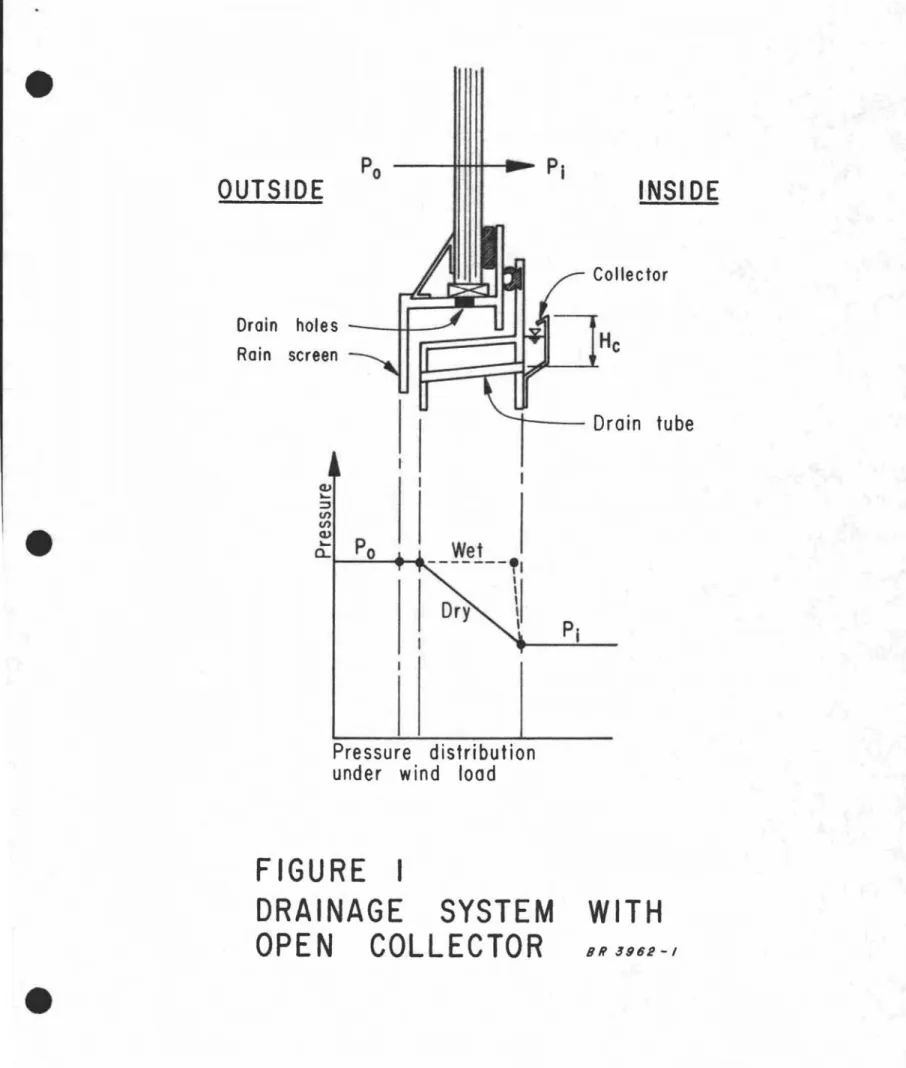
Two examples of drainage system design are shown in Figures 1 and 2 that can, depending on the magnitude of the acting wind pressure, either retain or drain the collected water. The system shown in Figure 1 utilizes an open
collector which drains to the outside through tubes. The outer ends of the drain tubes are protected by a rain screen to prevent rain entry through the drainage system; the se-paration between the screen and window frame is sufficient to prevent water from bridging the gap. Water accumulated in the collector during adverse wind conditions can drain outwards provided the wind pre s sure difference remains less than the collector head, H • Water bubbling, caused by wind blowing through the drcfln openings, is prevented from splashing onto the wall by the lip configuration of the collector. The drain tube diameter should be greater than l in. to ensure proper drainage but the number of tube s should be limited to prevent excessive air leakage. For example, the air flow through eighteen, l-in. diameter holes would be equivalent to the flow through a window with 16 ft of sash crack having a leakage characteristic of
!
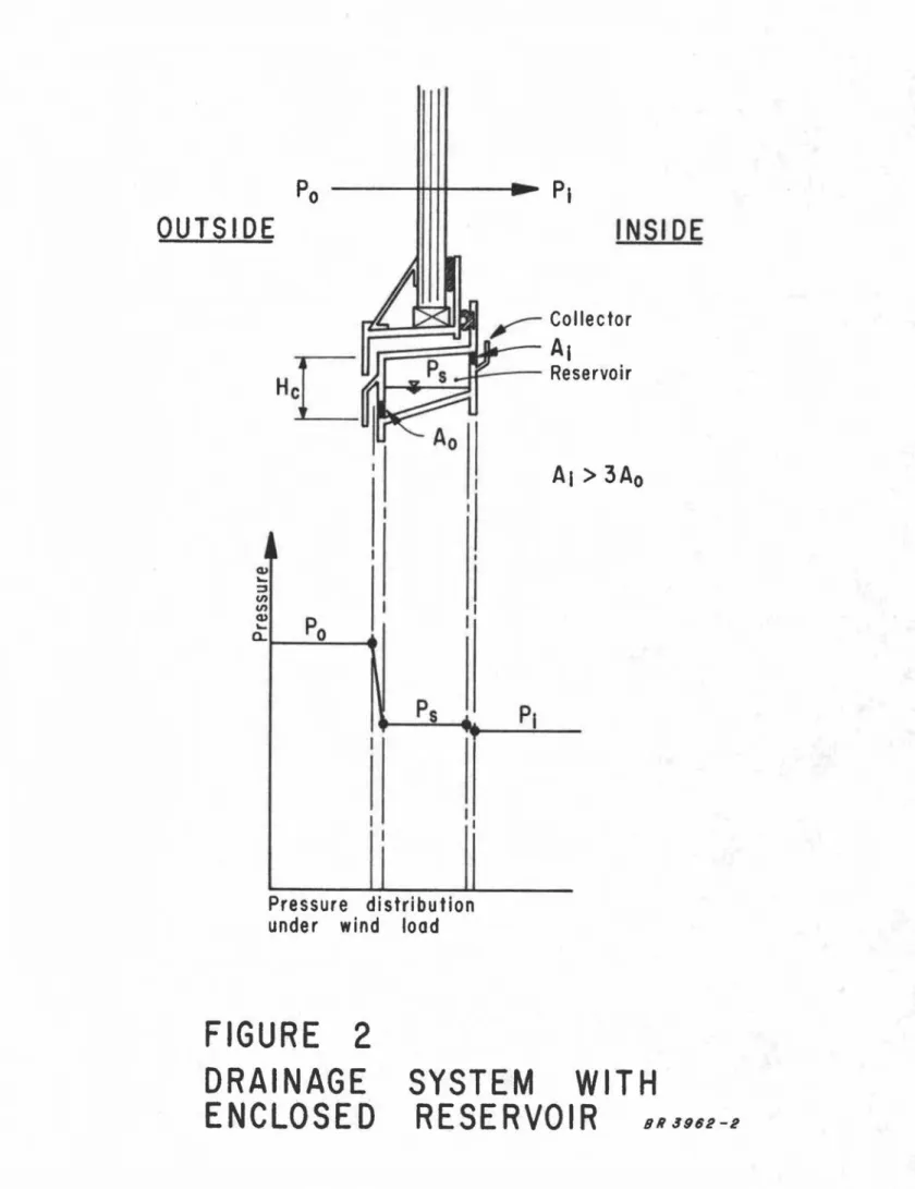
cu ft per (min) (ft of sash crack) at a pressure difference of 0.30 in. of water.The design shown in Figure 2 is similar to that in Figure 1 except for the hollow sill section, which acts as an enclosed reservoir. The outer openings, A , sustain most of the wind pressure; consequently, the air pressure in the reservoir is nearly equal to that in the room and water can .drain from the collector to the reservoir through A. even
with an adverse wind. The required air pressure distribution is achieved by making A. several times larger than A. The ratio of the pressure dr6ps across the inner and outei' openings is inversely proportional to the ratio of their areas squared; therefore, the pressure drop across the inner openings is only 1/9 of that across the outer openings when A is 1/3
o
of A .. 1
Drainage from the reservoir to outside is the same as that in System 1. Bubbling caused by air entry is prevented from wetting the interior wall by the reservoir configuration. Care is required in rendering the reservoir water-tight, especially at the junctions with the jambs. The area of the outer drainage openings should be sized for adequate drainage and minimum air leakage. It should be noted that proper drainage through the reservoir can only be accomplished if the inner drain holes are not all blocked with water at once.
OUTSIDE -DRAINAGE SYSTEMS FOR HORIZONTAL-SLIDING WINDOWS To control condensate run-off and to act as a secondary defence against rain penetration, the method commonly used in horizontal-sliding windows is the drainage system draining to outside. The designs of drainage systems for single and double windows should be considered separately, as the problems associated with each are different.
The rain- screen principle is not readily adapted to the
design of single horizontal-sliding windows because of the difficulty in maintaining a continuous inner air - seal at the intersections of the meeting rail and the head and sill tracks. ,Some rain leakage can, therefore, be anticipated and the drainage system should be designed to drain water against an adverse wind pressure.
Unlike the situation with single sliders, the rain-screen principle is ideally suited to the de sign of double horizontal sliders; the outer or storm unit can act as a partial rain screen for the inner or prime unit. The potential for rain leakage can be reduced by making the air-tightness of the inner unit many times that of the outer so that only a fraction of the total wind pressure difference acts across the outer unit. Rain leakage may not be completely eliminated, however, and a drainage system capable of draining against a wind pressure should be provided at the outer unit. If this system succeeds in keeping water from the inner unit, an inner drainage system would only be required to handle condensate run-off and can be designed to retain the collected water during wind action.
Examples of drainage systems for horizontal-sliding windows are shown in Figures 3 and 4 utilizing the same
concepts as shown in Figures 1 and 2. The windows in Figure 3 incorporate open water collectors and those in Figure 4 incorporate enclosed reservoirs.
The drainage systems for the outer unit of double windows and the drainage systems of single windows are both designed to drain water against a wind pressure. The
collector head, H , required for drainage in the single windows is equal fo the maximum anticipated wind pressure difference, セー ; that required at the outer unit of double windows need o'il'ly be a fraction of l'lP by utilizing pres sure
I , t' w
equa lza lon.
The drainage systems for the inner unit of double windows are de signed to retain condensate during periods of
wind action. They function independently of the outer
drainage systems even though the run-off does pass through the storm unit on its way outwards.
SUMMARY
Water on the inside surface of windows re suIting from condensation or rain leakage can be controlled using evaporation gutters or drainage systems draining to the inside or the outside.
The one most commonly employed is that draining to the outside. When incorporated in Canadian windows, this
system encounters difficulty with freezing and wind action. Care must be exercised in the de sign of the outside -drainage system to prevent the entry of wind-driven rain through the drainage opening and to prevent water collected on the inside from blowing onto the inside wall surface.
The drainage systems for the outer unit of double horizontal sliders and for single horizontal sliders, as presently designed, are required to assist in the control of rain leakage as well as condensate run-off. These systems must be designed to allow drainage of water against wind pressure. 1£ the outer drainage system is properly designed, the inner drainage system need only control condensate run-off.
He
Collector
WITH
81i 3962-1 - r - - _Drain tube
Wet
---"
\1
IPressure distribution
under wind load
FIGURE
I
DRAINAGE
SYSTEM
OPEN
COLLECTOR
Drain
holes
--+1--Rain
screen
r==:=:::::;
•
セセセ
, - Collector
r=:=::=::=-...I..--
A
I
I r _ _Reservoir
AI> 3A
o
I I.i
Pressure distribution
under
wind
load
FIGURE
2
DRAINAGE
e
e
e
Run - off drains
.,..,
OUTS I DE
I - M_NN]イjGセ 4-Z_J _Connecting
holes
Outer
holes
セ
Connecting
holes
Outer
holes
II 11セーセ
W -·II-.---rT-.---IIOUTSIDE
"I ::
II II , ! , ,L_J LSIDE SECTION
PLAN VIEW
- Drainage
occurs when
He
>
セpw
- Area
of outer drain
holes should be limited for
minimum
air leakage
- No limit on areas of run - off holes or connecting
holes
FIGURE
3
(a)
DRAINAGE
SYSTEM
FOR HORIZONTAL - SLIDING
SINGLE
SLIDER
WITH
OPEN
COLLECTOR
WINDOWS
e
e
e
Run -off drains
セMMMMMMMMMMMMMMMMM
OUTSIDE
Drain holes
(A
I
1
Thermal break
MMMMMイMM]セ]Nj,
Drain holes
Connecting holes
(A2
l
- - ---::z.
イMセ⦅] ..J _ I1+
- 1 - - - . . . ,PRIME
UNIT
sjセiセm vMセM---.---¥
i'"
-
-
}
break
Condensate
collector
STORM
PRIME
UNIT
UNIT
:: It II II 'I ,I8P
WH
p
hウセ
セ]]ゥi
ijNpウセセ
OUTSIDE
II li:1
IIlill
セpー
- Rain leakage is controlled
if
H
s
>
IJ.Ps
- A
2 should
be limited to equivalent of 3, 1/4
11セ
holes
FIGURE
3 (b)
DRAINAGE
SYSTE M
DOlJBLE
SLIDER
WITH
FOR
HORIZONTAL - SLIDING
OPEN
COLLECTOR
WINDOWS
e
e
e
ff hal RA
OUTSI DE
Ai
セ
I1+
c
l -I-,
I
セ I I-,
I セ J IIn
I -I \ I•
f"'\ L... .-''"1''\..
orr -....: Inner drains(Ad
Outer drains(A
o)
I II I II I II I II---tt-tH-H--LiP
w I " I 1.1.r
-I I I I I I Run - off holesOUTSIDE
SIDE
SECTION
PLAN
VIEW
- For drainage I
Ai> 3 A
oH
>
LiP
w
- A
o should be limited to equivalent of 3I
1/4II'
holes- Reservoir should be isolated from inside and outside except for holes
FIGURE
4
(0)
DRAINAGE
SYSTEM
SINGLE
SLIDER
WITH
FOR
HORIZONTAL - SLIDING
ENCLOSED
RESERVOIR
WINDOWS
8 R 3 9 6 2 - 5
e
e
e
'Ther.mal
break/Ii
AI
L-
---
L---
---OUTSIDE
A4
-
---....,
I.L