HAL Id: hal-00667832
https://hal.archives-ouvertes.fr/hal-00667832
Submitted on 10 Feb 2012
HAL is a multi-disciplinary open access
archive for the deposit and dissemination of
sci-entific research documents, whether they are
pub-lished or not. The documents may come from
teaching and research institutions in France or
abroad, or from public or private research centers.
L’archive ouverte pluridisciplinaire HAL, est
destinée au dépôt et à la diffusion de documents
scientifiques de niveau recherche, publiés ou non,
émanant des établissements d’enseignement et de
recherche français ou étrangers, des laboratoires
publics ou privés.
The ARUM Experimentation Platform : an Open Tool
to evaluate Mobile Systems Applications
Marc-Olivier Killijian, Matthieu Roy, Gaetan Severac
To cite this version:
Marc-Olivier Killijian, Matthieu Roy, Gaetan Severac. The ARUM Experimentation Platform : an
Open Tool to evaluate Mobile Systems Applications. AMiRE 2011: 6th International Symposium
on Autonomous Minirobots for Research and Edutainment, May 2011, Bielefeld, Germany. pp.1.
�hal-00667832�
Open Tool to evaluate Mobile Systems
Applications
Marc-Olivier Killijian, Matthieu Roy, and Gaetan Severac
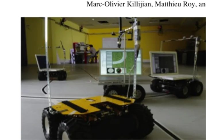
Abstract This paper present the ARUM robotic platform. Inspired by the needs of realism in mobile networks simulation, this platform is composed of small mobiles robots using real, but attenuated, Wi-Fi communication interfaces. To reproduce at a laboratory scale mobile systems, robots are moving in an 100 square meters area, tracked by a precise positioning system. In this document we present the rational of such simulation solution, provide its complete description, and show how it can be used for evaluation by briefly explaining how to implement specific algorithms on the computers embedded by the robots. This work is an application of multi-robotics to research, presenting solutions to important problems of multi-robotics.
1 Objectives
In this paper, we present the ARUM robotic platform1targeted at evaluating perfor-mance, resilience and robustness of mobile systems. To obtain an efficient evalua-tion platform, three specific criteria were considered: Control condievalua-tions (real time monitoring, repeatability, flexibility, scalability), Effective implementation (easi-ness of configuration, devices autonomy, portability, low cost, miniaturization), and Realistic environment (network scale, traffic load, node mobility, positioning, ra-dio broadcast behaviour). To our knowledge this platform is the only one to date to integrate all these features in a single environment.
Marc-Olivier Killijian, Matthieu Roy
LAAS–CNRS, 7 avenue du colonel Roche, 31077 Toulouse, France Universite de Toulouse e-mail: [email protected]
Gaetan Severac
ONERA (DCSD), The French Aerospace Lab, 31055 Toulouse, France, Universit´e de Toulouse, e-mail: [email protected]
1ARUM stands for “an Approach for the Resilience of Ubiquitous Mobile Systems”
Fig. 1 A picture of the the ARUM Platform
Indeed, current evaluation strategies for distributed and mobile systems can be split in five categories:
• Simulators. Simulators are cheap and fast to set up, with almost no limitation in the number of nodes. Due to their scalability and simplicity, they are well suited for initial testing. Furthermore, they may speed up development of theoretical researches because since they allow a perfect monitoring and repeatability [21, 22]. Nevertheless, simulation is based on models of the running environment, and thus cannot reflect the real complexity of natural environments, particularly for radio communication and mobility pattern[7, 5, 3] .
• Emulators. Emulators are built to physically reproduce connections events us-ing real wired network hardware[16, 19]. They provide features interestus-ing for protocol implementation but they still use simulation to reproduce wireless com-munication behaviour and mobility[4].
• Testbeds. The ARUM platform we present in this paper can be classified in this category. Testbeds are closer to reality thanks to the use of real hardware. They exist since years now, from the historical MIT RoofNet[1], to the more recent MoteLab2service. Ideal to finalize and validate applications before real-life ex-perimentations, testbeds provide much more realistic results than emulators or simulators. But they are also expensive, time consuming and limited by the phys-ical resources/hardware used[14]. Because of those limitations, only a few of them implement real mobility. To the best of our knowledge, two platforms using mobile robots have been recently developed: MINT[17] and Mobile Emulab[10]. Original solutions that emulate mobility can also be found in the literature, like MOBNET [6] which varies the transmission power levels of fixed access points. It is interesting to notice that most of these platforms have to deal with large vari-ations in the communication noise level because of environment perturbvari-ations.
Such difficulties can be problematic during applications development phases, but they are representative of conditions encountered in the real life.
• Hybrid simulators use both simulated networks and real devices, taking advan-tages and disadvanadvan-tages of each[18, 23]. They are particularly suited to study, at a low cost, the interconnection of some real devices to a huge network, the latter being simulated.
• Real live experiments. This is, obviously, the more realistic kind of experimen-tation, but they present inherent technical problems which can bring more tech-nical difficulties than scientific benefits[11, 15]. They are absolutely necessary for commercial applications, because it is impossible to truly simulate real envi-ronment yet. Yet, they are very expensive, error-prone, and they do not provide repeatability of experiments, due to the wide variability of real environments. As such, such platforms are not used in the context of research and education.
Fig. 2 Accuracy of evaluation solutions for mobile systems depending on their respective costs
Among all these technologies, there is no good or wrong solutions, the best choice depends on a specific needs and available resources, as shown in Figure 2.
In our case, both for scientific and for demonstration reasons, we decided to im-plement a testbed, the ARUM platform. Indeed our primary goal was to comim-plement simulation and allow realistic evaluation of mobile systems, at a laboratory scale. It finally appeared to be a good platform for demonstration and education, since the platform can be used pedagogically to present various aspects and problems raised by mobile systems. The work describe here is an application of mini-robots to re-search, in a field different from robotics. However the solutions tested and imple-mented here can be applied to several important problems in multi-robotic field (e.g. positioning, mobility, communication...).
2 Design
To complete the goals presented in previous section, we designed an experimental evaluation platform composed of mobile devices. We dispose of a room of approxi-mately 100m2to emulate systems of different sizes, hence we decided to scale every
parameter of the system to fit within our physical constrains. Technically speaking, each mobile device is built with : a programmable mobile hardware able to carry the device itself, a lightweight processing unit equipped with one or several wireless network interfacesand a positioning device. Hardware modelling required a reduc-tion or increase of scale to be able to conduct experiments within the laboratory. To obtain a realistic environment, all services have been modified according to the same scale factor.
Device Real Accuracy Scaled Accuracy Wireless range: 100m range: 2m
GPS 5m 10cm
Node size a few meters a few decimeters Node speed a few m/s less than 1m/s Table 1 Scale needs
In our case, we considered vehicular ad-hoc network experiments [13]. A typi-cal GPS embedded in a moving car is accurate to within 5-20m. So, for our 100m2 indoor environment to be a scaled down representation of a 250000m2outdoor en-vironment (a scale reduction factor of 50), the indoor positioning accuracy needs to be 10 − 40cm. Table 1 summarizes the required change in scale for all peripherals of a node.
We understand here that to meet those requirements some parts of the develop-ment were much more important. The focus was put on the reduced Wi-Fi interfaces, the precise positioning and the node mobility.The different parts of the platform will be detailed in the following section.
3 Technical solutions
3.1 Mobility
To reproduce mobile systems conditions, the devices used in the platform must be mobile. But when conducting experiments, a human operator cannot be behind each device, so mobility has to be automated. This is why we considered the use of simple small robots in order to carry around the platform devices. The task of these robots is to implement the mobility of the nodes following a movement scenario.
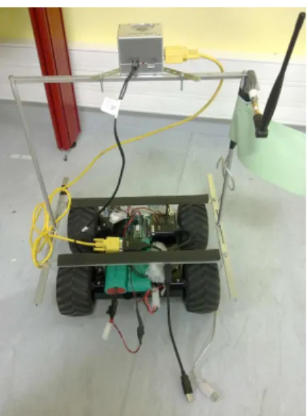
Fig. 3 A Mobile Node Picture, without the embedded computer
A node, represented in figure 3, is implemented in the system using a laptop computer that is carried by a simple robotic platform, that includes all hardware devices, the software under testing and the software in charge of controlling robots movements. Notice that software under testing and control software are totally in-dependent, there are running on the same computer for practical reasons only.
For the mobile platform we use Lynxmotion 4WD rover. We selected it instead of other smaller robot (e.g. Lego Mindstorm) because this rover is able to carry a payload of 2 Kg during a few hours, running at a maximum speed of 1m/s. It is also relatively cheap (cf. table 2) and easy to build. We equipped it with infra-red proximity sensors to avoid collision, a top deck to support the laptop, a positioning system and a modified Wi-Fi interface.
The motion control software, running on the carried laptop, communicates speeds orders (linear speed and angular speed) to the robot. The mobility patterns are drawn by an operator for each mobile robot, using a dedicated software, that sends it to the mobile nodes control software. This enables flexibility – each node has its own mobility pattern – and repeatability – a pattern can be saved and replayed.
3.2 Localization
Positioning is a critical point of the platform. Firstly, we need to reproduce the kind of information produced by actual market solutions such as GPS, pondered by our scale factor. Secondly, we need a precise and real-time position of the mobile node to allow an accurate motion control of the robot. Our specifications required a
precision within the centimetre and a minimum refresh of 2 Hz. Several technologies are currently available for indoor location [9], mostly based either on scene analysis (e.g. using motion capture systems) or on triangulation (of RF and ultrasound [20] or wireless communication interfaces [8]). During the building of the platform, we tried four different solutions.
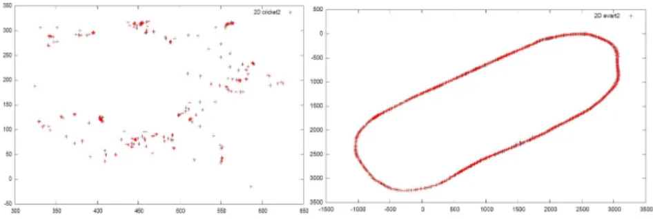
We first tested the Cricket system [20], developed by MIT. Cricket is based on si-multaneous ultrasound/RF messages and triangulation. Beacons fixed on the celling send periodically RF message with their ID and position, and, in the time, they send an equivalent message by ultrasounds. The flight time of the RF message is insignificant compare to that of the ultrasound. So the receiver, embedded on the mobile robot, can estimate the flight time of the ultrasound messages and and cal-culate, with at least 3 different messages received, its position. This position is then send to the mobile node via a serial connection. In theory, this system is very effi-cient, but in practice we were confronted to important limitations due to ultrasound disturbances. The ultrasound speed in the air can change depending of the temper-ature, so the results obtained can vary in the same way, and the ultrasound are also very sensitive to noise and perturbations. Neon lights was perturbing the systems and robots vibration, when they were moving, generated a lot of disturbances in the results. Finally we had to abandon this technology.
Fig. 4 Comparative results of Ultrasounds (left) and Infra-red (right) positioning systems. A robot is tracked by the two different systems while following the same circuit drew on the floor
To reach our desired level of accuracy for indoor positioning, we then used a dedicated motion capture technology that tracks objects based on real-time analysis of images captured by fixed infra-red cameras. The Cortex system3is able to
local-ize objects at the millimetre scale. This technology uses a set of infra-red cameras, placed around the room, that track infra-red-visible tags. All cameras are connected to a server that computes, based on all cameras images, the position of every tag in the system. We equipped our small robots with such tags to get their positioning information. The figure 4 shows compared results of the ultrasounds and infra-red systems. Although the precision attained was more than enough for our needs, the system has some drawbacks: the whole system is very expensive (in the order of
100kEuros), calibration is a tedious task, and infra-red signals cannot cross obsta-cles such as humans.
The localization system currently used is the Hagisonic StarGazer technology4. It is also based on infra-red camera but they are small and embedded on-board on the mobile robots. They locate themselves by tracking statically placed infra-red-visible tags. With Hagisonic, a camera needs to see only one single tag to be able to calcu-late its position and the precision is about a few millimetres, with a frequency of 10 Hz. So this technology, more affordable, was plenty satisfying our requirements.
An Ultra-Wide-Band-based localization system (UWB), by Ubisense5, has also been deployed and used for the experiments. Localization is performed by 4 sensors, placed in the room at each corner, that listen for signals sent by small tags that emit impulses in a wide spectrum. Such impulses can traverse human bodies and small obstacles, so the whole system is robust to external perturbation, but, from our preliminary measurements, attainable precision is about 10cm. The next step will be to couple this technology with the Hagisonic camera system, resulting in a localization system with better properties: it will be relatively cheap, robust to external perturbations such as obstacles, and will have most of the time a precision about the order of a centimetre.
To keep our experimental platform positioning system generic, despite the nu-merous different technologies used, we developed a position server, accessible via the supervision wireless network of the experimentation room. Two kinds of clients can communicate with it, using standard XML messages. A client can be a position provider (Cortex, Hagisonic, UWB...) and send to the server the position of one or several mobiles or the client can be a position consumer (supervision applica-tion, motion control software...) and ask to the server the position of one or several mobiles. Using this strategy, it is possible to change the technology of one system, provider or consumer of position, and the modification will remain transparent to all the other devices.
3.3 Scenario Drawing Interface
To have adequate experimental conditions, the mobile nodes of the platform need to follow and repeat defined mobility scenario. But first, an operator has to define the mobility scenario. We developed a graphical user interface to draw, configure, visualize and manage mobility patterns. Now the interface is a complete program composed of 7 different tabs, figure 5 shows a screen-shot. The Point tab where users can define passage points on a map. The Route tab to edit robots routes using the passage points previously created, the trajectory will be calculate from those routes, it is also possible to specify time constraints and add some pauses in the route execution. The Simulation tab permits to see an overview of the robots movements,
4Hagisonic - http://www.hagisonic.com/
you can select the different routes you want to visualise. The Rovers tab is used to configure the TCP/IP connexion attributes to communicate with the robots. You can select the route each robot will execute in the Association tab. The Upload tab is designed to send the routes to the corresponding robots and start, stop or pause their executions. Finally the Remote Control tab allows to manually control a robot, with a virtual joystick, and give the possibility to dynamically define a route from its movements. The interface is coded in Java and can be run on any computer connected to the supervision network. The mobility scenarios and movement orders are send to the mobile node via ”Java Remote Method Invocation” (Java RMI).
Fig. 5 Screen-shot of the mobility scenario drawing interface
3.4 Motion control and trajectory computing
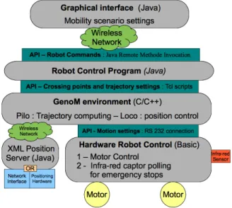
As you can see on figure 6, the mobility scenarios defined with the GUI are sent to the robot via Java Remote Method Invocation” (Java RMI). A robot control pro-gram, coded in Java, receives a scenario description or the movements orders from the scenario drawing interface. This program is running on the embedded computer of the mobile node. The mobility scenarios are then converted into commands and sent to the robot motion control environment. This environment is composed of GenoM6 modules in charge of computing the final trajectory and controlling the
robot speed to follow it. Proximity infra-red captors are continuously polled to stop the robot if an obstacle is detected.
We chose the GenoM environment, developed at the LAAS-CNRS laboratory, because it is an open source solution, already functional and still maintained by the robotic community. GenoM is a tool to design real-time software architectures. It is more specifically dedicated to complex on-board systems, such as autonomous mobile robots or satellites. It allows to encapsulate the operational functions on independent modules that manage their execution. The functions are dynamically started, interrupted or (re)parametrized upon asynchronous requests sent to the mod-ules. A final reply that qualifies how the service has been executed is associated to every request. The modules are automatically produced by GenoM using a common generic model of module and a synthetic description of the considered module. At the end a set of modules composes an open, communicant and controllable system. Such environment can be very powerful and it used in our laboratory to control complex robots. In this platform, where the environment is controlled, the mobility is very simply implemented and we only used two GenoM modules. The module ”Pilo”, to compute the final trajectory (using Euler spirals) and the module ”Loco” which controls the robot speed to follow the trajectory. The ”Loco” module uses the position system to get in real time the position of the mobile node and send required linear and angular speed orders to the motors control card of the robot, through a serial connexion.
3.5 Reduced wireless communication
The communication range of the participants (mobile nodes and infrastructure access-points) has to be scaled according to the experiment being conducted. For our first experimentation, the scale factor had to be 50 (cf. Table 1) but, ideally, the communication range should be variable. Some Wi-Fi network interface drivers propose an API for reducing their transmission power. But the implementation of this feature is often rather limited, or ineffective, at a single room scale. A satisfy-ing solution consists in ussatisfy-ing signal attenuators7placed between the Wi-Fi network interfaces and their antennas. The necessary capacity of the attenuators depends on many parameters such as the power of the Wi-Fi interfaces and the efficiency of the antennas, but also on the speed of the robot movements, the room environment, etc. As it is impossible to predict or calculate the Wi-Fi radio wave propagation we con-ducted empirical experimentation[12] to establish the relationship between signal attenuation and communication range, figure 7 show a picture of an experimenta-tion.
Fig. 7 The attenuation WiFi experiments
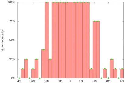
This experiment involves two laptops mounted on a mobile robot platforms and using an external Wi-Fi interface to communicate with each other. One of the two nodes is static and the other one moves back and forth. Equivalent attenuators are attached between each external Wi-Fi interface and its antenna. The mobile platform moves along a line, stops every 20cm for 5min and performs a measurement at every
7An attenuator is an electronic device that reduces the amplitude or power of a signal without appreciably distorting its waveform.
stop, figure 7. For each measurement, the moving laptop joins the ad-hoc network created by the fixed one, measures the communication throughput and then leaves the ad-hoc network. The time for joining the network is logged, as is the measured throughput. A complete experiment is composed of 100 repetitions of a return trip along the 5m line. This data is logged and statistically analysed off-line, leading to figure such as the one presented on figure 8. To validate that those attenuated results correspond to real Wi-Fi propagation behaviour, we reproduce the same experiment, outdoor, without attenuation and we obtain exactly the same kind of graphic shape, distances range excepted of course. Thanks to those multiple results we can now use the adequate attenuation depending on the specification of the experiments and we can certify that this will be representative to real Wi-Fi connexion conditions.
Fig. 8 The attenuation WiFi experiments
3.6 Supervision network
For the communications between the collaborative algorithms tested on the plat-form, the attenuated Wi-Fi interfaces previously presented are used. So the internal wireless card of the embedded computers is available for monitoring. Connected to a LAN access point, it provides direct access to each computer without disrupting the current experiment. This system is used to send monitoring information to the robot (e.g. position, commands, ...) and to retrieve data from the mobile nodes in real time, allowing a dynamically overview and analysis of the tested algorithms.
3.7 Implementation and Price
It is interesting to consider that all the different parts of a mobiles nodes (localiza-tion, trajectory planning, robot control, communica(localiza-tion, ...) are connected thought clearly defined and documented interface, so it is easy and fast to change one of this part to make the platform evolve, without re-designing everything (cf. figure 6). For example we envisage buying a new localization system and changing the Lynx-motion robot for a Roomba8development mobile platform. Anyone interested in reproducing our evaluation platform in a laboratory can reuse some parts of interest and modify others. Full documentation and sources of the platform are available at: http://projects.laas.fr/ARUM/. As an indication, Table 2 sums the actual price of the different parts of a mobile node.
Device Price ($)
Linxmotion mobile Platform Kit 1 000
Hagisonic IR Camera 1000
Wireless WiFi interface 50
Attenuators 70
Laptop 1200
Serial-USB Adaptors 30
Total 3350
Table 2 Platform devices Costs
4 Experimentation and Lessons Learnt
To evaluate our ARUM platform, we experiment the Distributed Black-Box appli-cation, or DBB for short. This work was conducted in the course of the European project HIDENETS9. The application developed provides a virtual device, whose
semantics is similar to avionics black-boxes, that tracks cars history in a way that can be replayed in the event of a car accident. It ensures information is securely stored using replication mechanisms, by means of exchanging positions between cars. This architecture is a partial implementation of the HIDENETS architecture and has been detailed in the project deliverable [2].
The ARUM platform was used to emulate the network of communicating cars. Through this work, the global performance of the evaluation platform was vali-dated. The modularity and repeatability of the mobility patterns was used to test and improve the DBB algorithms in controlled situations. The use of real, power
8Roomba Devel - http://www.irobot.com/images/consumer/hacker/roombascispecmanual.pdf 9HIghly DEpendable ip-based NETworks and Services - http://www.hidenets.aau.dk/
reduced Wi-Fi interfaces allowed realistic results; we monitored during the experi-ment wireless signal variations similar to real wireless network behaviour in difficult conditions (maximum range limit, noise perturbation, obstacle, ...).
A very precise positioning system was used both by the tested cooperative algo-rithms and the robot motion control software, without disturbances. With hindsight we have to admit that, even if we get positive results, we had to deal with a lot of contingencies. The total labour cost of the platform development was more conse-quent than expected. Some parts of the development would have been impossible to reduce - attenuated Wi-Fi scaling, positioning systems tests - but if we had to rebuild all from scratch we would probably choose a mobile robotic platform that already has motion control implemented - such as the Roomba Devel platform.
However, now that the platform is finished and validated, it can be used as a tool “out of the box”; anyone can come to the laboratory to implement algorithms on the mobile nodes. As showed in Section 3, it is possible to interface any code with the different parts of the mobile node - communication, positioning, monitoring, ... - and to easily program a mobility pattern. All the parts of the platform are segmented by software interfaces, defined in the documentation10, so it can quickly be handled and adapted by anybody interested. Additionally the sources of each software module can be downloaded to build a similar platform in another laboratory.
Even if it is not the primary function of this platform, we noticed that the versatil-ity and the easiness of use of this platform makes it an interesting educational tool. All the different parts of it, presented in Section 3, can be used, studied and replaced by students. The localization, the mobility scenario computing, the motion control and trajectory calculation or the reduces wireless communication, could support in-teresting university work.
5 Conclusion
This article started by pointing out the difficulties of evaluation of application for mobile devices systems. It presented the difficulties encountered to emulate a realis-tic mobile network environment at a laboratory scale. Those observations motivated the development of a testbed platform designed to evaluate distributed applications. Thanks to use of mini-robots, this platform, named ARUM, appears to provide an in-teresting compromise between resources consumption (in terms of manpower) and accuracy of results, appropriate to complement simulation. The whole architecture is described part by part to ease reuse by researchers or in an educational context, while reducing the waste of time and money in development and tests.
References
1. D Aguayo, J Bicket, S Biswas, and D De Couto. Mit roofnet: Construction of a production quality ad-hoc network. MobiCom Poster, 2003.
2. J. Arlat and M. Kaˆaniche(editors). Hidenets. revised reference model. LAAS-CNRS, Contract Report nr. 07456, Septembre 2007.
3. Elyes Ben Hamida, Guillaume Chelius, and Jean-Marie Gorce. Impact of the Physical Layer Modeling on the Accuracy and Scalability of Wireless Network Simulation. Simulation, 85:574–588, 09 2009.
4. Razvan Beuran, Lan Tien Nguyen, Toshiyuki Miyachi, and Junya Nakata. Qomb: A wireless network emulation testbed. IEEE GLOBECOM 2009, 2009.
5. D Cavin, Y Sasson, and A Schiper. On the accuracy of manet simulators. POMC’02: Proc. of the second ACM international workshop on Principles of mobile computing, pp 38–43, 2002. 6. Kun chan Lan, Eranga Perera, and Henrik Petander. Mobnet: the design and implementa-tion of a network mobility testbed for nemo protocol. 14th IEEE Workshop on Local and Metropolitan Area Netw, 2005.
7. Kwan-Wu Chin, John Judge, Aidan Williams, and Roger Kermode. Implementation experi-ence with manet routing protocols. ACM SIGCOMM Computer, 2002.
8. N. S. Correal, S. Kyperountas, Q. Shi, and M. Welborn. An uwb relative location system. Proc. of IEEE Conference on Ultra Wideband Systems and Technologies, Novembre 2003. 9. J. Hightower and G. Borriello. A survey and taxonomy of location systems for ubiquitous
computing. IEEE Computer, 2001.
10. D. Johnson, T. Stack, R. Fish, D. Montrallo Flickinger, L. Stoller, R. Ricci, and J. Lepreau. Mobile emulab: a robotic wireless sensor network testbed. IEEE INFOCOM, 2006. 11. Wolfgang Kiess and Martin Mauve. A survey on real-world implementations of mobile ad-hoc
networks. Ad Hoc Networks, (5):324 – 339, 2005.
12. M.O. Killijian, D. Powell, M. Roy, and G. S´everac. Experimental evaluation of ubiquitous systems: Why and how to reduce wifi communication range. DEBS’08, 2008.
13. M.O. Killijian, M. Roy, G. S´everac, and C. Zanon. Data backup for mobile nodes : a cooper-ative middleware and experimentation platform. DSN’09 WADS, 2009.
14. Matthias Kropff, Tronje Krop, Matthias Hollick, Parag S. Mogre, and Ralf Steinmetz. A survey on real world and emulation testbeds for mobile ad hoc networks. Proceedings of 2nd IEEE International Conference on Testbeds and Research Infrastructures for the Development of Networks and Communities (TRIDENTCOM 2006), 2006.
15. K. Langendoen, A. Baggio, and O. Visser. Murphy loves potatoes: experiences from a pi-lot sensor network deployment in precision agriculture. Parallel and Distributed Processing Symposium, International, 0:155, 2006.
16. Michael Matthes, Holger Biehl, Michael Lauer, and Oswald Drobnik. Massive: An emulation environment for mobile ad-hoc networks. Proceedings of the Second Annual Conference on Wireless On-demand Network Systems and Services (WONS’05), 2005.
17. Christopher Mitchell, Vikram P. Munishwar, Shailendra Singh, and Xiaoshuang Wang. Testbed design and localization in mint-2: A miniaturized robotic platform for wireless pro-tocol development and emulation. Proc. First International Conference on Communication systems and Networks (COMSNETS), 2009.
18. Fredrik Osterlind, Adam Dunkels, and Thiemo Voigt. Sensornet checkpointing: Enabling repeatability in testbeds and realism in simulations. Wireless Sensor Networks, pages 343– 357, 2008.
19. M. Puˇzar and T. Plagemann. Neman: A network emulator for mobile ad-hoc networks. Tech-nical Report 321, ISBN 82-7368-274-9 Dept. of Informatics, University of Oslo, 2005. 20. A. Smith, H. Balakrishnan, M. Goraczko, and N. B. Priyantha. Tracking moving devices with
the cricket location system. 2nd International Conference on Mobile Systems, Applications and Services (Mobisys 2004), Boston, MA, June 2004.
21. I. Stojmenovic. Simulations in wireless sensor and ad hoc networks: matching and advancing models, metrics, and solutions. IEEE Communications Magazine, 46(12):102–107, 2008.
22. J. Boleng T. Camp and V. Davies. A survey of mobility models for ad hoc network research. Wireless Comm. and Mobile Computing, 2:483–502, 2002.
23. J Zhou, Z Ji, and R Bagrodia. Twine: A hybrid emulation testbed for wireless networks and applications. IEEE INFOCOM, 2006, 2006.