HAL Id: hal-01852204
https://hal.archives-ouvertes.fr/hal-01852204
Submitted on 1 Aug 2018
HAL is a multi-disciplinary open access
archive for the deposit and dissemination of
sci-entific research documents, whether they are
pub-lished or not. The documents may come from
teaching and research institutions in France or
abroad, or from public or private research centers.
L’archive ouverte pluridisciplinaire HAL, est
destinée au dépôt et à la diffusion de documents
scientifiques de niveau recherche, publiés ou non,
émanant des établissements d’enseignement et de
recherche français ou étrangers, des laboratoires
publics ou privés.
Mechanical behavior of black anodic films on 7175
aluminium alloy for space applications
Yann Goueffon, Catherine Mabru, Michel Labarrère, Laurent Arurault, Claire
Tonon, Pascale Guigue
To cite this version:
Yann Goueffon, Catherine Mabru, Michel Labarrère, Laurent Arurault, Claire Tonon, et al..
Mechani-cal behavior of black anodic films on 7175 aluminium alloy for space applications. Surface and Coatings
Technology, Elsevier, 2009, 204 (6-7), pp.1013-1017. �10.1016/j.surfcoat.2009.06.026�. �hal-01852204�
Any correspondence concerning this service should be sent to the repository administrator:
staff-oatao@inp-toulouse.fr
O
pen
A
rchive
T
oulouse
A
rchive
O
uverte (
OATAO
)
OATAO is an open access repository that collects the work of Toulouse researchers
and makes it freely available over the web where possible.
This is an author -deposited version published in:
http://oatao.univ-toulouse.fr/
Eprints ID: 3811
To link to this article: DOI:10.1016/j.surfcoat.2009.06.026
URL:
http://dx.doi.org/10.1016/j.surfcoat.2009.06.026
To cite this document
: Goueffon, Yann and Mabru, Catherine and Labarrère, Michel and
Arurault, Laurent and Tonon, Claire and Guigue, Pascale ( 2009) Mechanical behavior of
black anodic films on 7175 aluminium alloy for space applications. Surface and Coatings
Technology, vol. 204 (n° 6-7). pp. 1013-1017. ISSN 0257-8972
Mechanical behavior of black anodic films on 7175 aluminium alloy for
space applications
Yann Goueffon
a,⁎
, Catherine Mabru
b, Michel Labarrère
b, Laurent Arurault
c, Claire Tonon
d, Pascale Guigue
aa
CNES, 18 Avenue Edouard Belin, 31401 Toulouse Cedex 9, France
b
Université de Toulouse, ISAE, Département Mécanique des Structures et Matériaux, 10 Avenue Edouard Belin BP54032, 31055 Toulouse Cedex 4, France
c
Université de Toulouse, CIRIMAT-LCMIE, Institut CARNOT, Université Paul Sabatier, 118 route de Narbonne, 31062 Toulouse Cedex 9, France
dEADS ASTRIUM Satellites, 31 Avenue des Cosmonautes, 31402 Toulouse Cedex 4, France
a b s t r a c t
Keywords: Black anodizing Thin films Crazing FlakingBecause of their low outgassing and their thermo-optical properties, black anodized aluminium parts are often used near optical instruments to manage thermal control in space applications. However, critical cases of flaking of the film were observed after simulated thermal ageing. To understand the mechanisms leading to flaking, the influence of the initial porosity of the film on its mechanical behavior during and after the black anodizing process has been investigated. The decrease of limit tensile stress with the porosity, the coloring and the sealing combined to thermal stresses due to the difference of thermal expansion coefficients between film and substrate have been shown to cause crazing in particular conditions. For high initial porosity films, thermal cycling ageing has a detrimental influence on the adhesion measured by scratch-testing. Numerical simulation has been used to simulate the combined effects of thermal stresses and film cracking on the stress field at the interface.
1. Introduction
Black anodic films on aluminium alloys are used in space industry since many years. Such treatments provide specific characteristics to surfaces (Solar absorptance αsN 0.93 and normal emittance εnN 0.90) managing passive thermal regulation. The process used to obtain these black films is based on porous anodizing. This is not a deposit of a coating but an electrochemical oxidation of the surface of the aluminium alloy. Therefore, the adhesion of anodic film on its substrate has always been considered very strong. Before the launch, parts of satellites are submitted to thermal cycles under vacuum to simulate the space environment. Cases of flaking of black anodic films have been observed after those tests when pulling-off tapes used to fix thermocouples[1].
In this context, the aim of the present paper is to better understand mechanisms leading to flaking. In order to precisely assess the mechanical behavior of the film, depending on its initial porosity, residual stresses were first measured after each step of the process. The coefficient of thermal expansion was then evaluated by beam bending analysis to determine the thermal stresses occurring during processing and ageing. After, the tensile strength was evaluated thanks to four-point bending tests. Finally, the evolution of adhesion during ageing (thermal cycling) was followed by scratch tests. A finite
element model was developed to simulate the combined effects of thermal stresses and film cracking on the stress field at the interface film/substrate.
2. Experimental procedure
2.1. Material
The substrate material was the 7175T7351 aluminium alloy, often used in space industry. Its chemical composition in weight percent is: 1.62%Cu, 0.12%Fe, 2.42%Mg, 0.01%Mn, 0.06%Si, 5.75%Zn, 0.041%Ti, 0.21%Cr and Al the remainder. Its Young modulus is Es= 72 GPa, its
Poisson coefficient is νs= 0.33 and its coefficient of thermal expansion
is αs= 2.34 × 10− 5K− 1.
2.2. Black anodizing process
The process of black anodizing followed the ESA Standard[2]for spacecraft design involving four consecutive steps: surface pretreat-ments, anodizing, coloring and sealing. Samples were rinsed with distilled water after each step.
The alloy sheet (3 × 20 × 40 mm or 10 × 20 × 160 mm) was degreased with ethanol and etched in Na2CO3(6.2 g/L) and Na3PO4
(12.5 g/L) aqueous mixed solution for 5 min at 93 °C and neutralized in aqueous HNO3(50%v/v) for 3 min at room temperature.
The aluminium sheet was used as anode and a lead plate as counter-electrode in the electrochemical cell. The anodizing was run Corresponding author. CNES, DCT/AQ/MP, 18 Avenue Edouard Belin, 31401 Toulouse
Cedex 9, France. Tel.: +33 561 339 150; fax: +33 561 339 095.
for 60 min in the galvanostatic mode (Ja= 1.2 ± 0.1A/dm²) using a
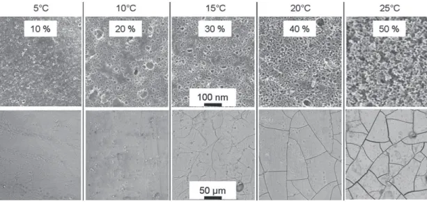
sulfuric acid solution (150 g/L) thermally regulated. Changing the anodizing temperature between 5 °C and 25 °C allow controlling the initial porosity (i.e. before coloring and sealing) (Fig. 1)[3–5]. Porosity was quantified by image analysis after observations with a field-emission gun scanning electron microscope (FEG-SEM JEOL JSM6700F device). The film thickness is around 20 µm to insert enough black dyes during the coloring.
The anodized part was colored by immersion in two successive baths: firstly for 15 min in a solution of cobalt acetate (200 g/L) regulated at 43 ± 2 °C, and then for 10 min in ammonium hydro-sulphide (30 g/L) at room temperature.
The sealing step occurred for 25 min in a bath at 98 ± 2 °C made up of nickel acetate (NiCH3COO, 4H2O) and boric acid (5 g/L both).
2.3. Residual stresses measurements in the film
Residual stresses in the film were measured by beam bending analysis. Thin substrates (200 µm) were prepared by a grinding on SiC paper (240–1200 grits) and polishing with diamond pastes from 6 µm to 1/4 µm; they were anodized on one side (20 mm × 20 mm). The curvatures of the samples induced by stresses were measured ex-situ on 17.5 mm with a Mahr Perthometer Concept with a sensor MFW250.
2.4. Coefficient of thermal expansion (CTE) determination
To evaluate the CTE of the film, curvature measurements were realized at different temperatures. Samples were warmed up to 130 °C with a heating stage and the film temperature was controlled with a thermocouple. Curvature measurements were performed during cooling (1 °C/min).
2.5. Film tensile strength measurements
The samples (160 × 20 × 10 mm) were anodized on a limited area. The tensile strength was determined with four-point bending tests performed on a tensile testing device (Adamel DY26) (Fig. 2). Acoustic emission measurements were used to determine the cracking load of the film (Lc). Post-experiment SEM observations were performed to
detect the presence of cracks in the film.
2.6. Adhesion measurements
Adhesion measurements were evaluated using a scratch-test device (CSM Revetest instrument) with a diamond stylus (Rockwell, 200 µm radius tip). Scratch tests were configured with an increasing normal load (loading speed: 30 N/min; advance speed: 5 mm/min). The resulting scratch-print of 5 mm length was observed by SEM to determine the corresponding normal load. Given values are averages of six different scratches on each sample.
2.7. Numerical simulation
A finite element simulation was used to evaluate mechanical behavior of a thin film on its substrate. SAMCEF was used to perform isotropic thermo-elastic calculations with 2-dimensional plane strain hypotheses. The geometry used was a substrate (thickness of 3 mm) with an anodic film of 20 µm. A straight crack perpendicular to the surface of 1 micron width and a variable length was added through the film. Mesh size has been validated by comparing KI with
theoretical values. Cases of crazing were sometimes observed just after the sealing step. Thus, the impact of the presence of a crack through the coating on the interfacial stresses has been observed when thermally loaded. For a preliminary analysis the interfacial stress is defined as the difference between stresses (direction parallel to the surface) in the coating and in the substrate near the interface. 3. Results and discussion
3.1. Residual stresses
Residual stresses have been measured after each step of the process for films with different porosities. The radius of curvature R of
Fig. 1. FEG-SEM surface views of anodic films with different anodizing temperatures before and after coloring and sealing at nano and meso scales. Fig. 2. Schema of the four-point bending test.
the thin sample is linked with stresses in the film byrelation (1) [6]. Stresses are considered to be uniform in the film:
σFilm= Efef 6Rð1−νfÞ 1 + 4αβ + 6α2β+ 4α3β+ α4β2 ð1 + αÞð1 + αβÞ ð1Þ with α =es ef and β = Esð1−νfÞ
Efð1−νsÞ es and efare the thicknesses of the
substrate and the film respectively. Poisson coefficient of the film, νf,
was assumed to be 0.28[7]. The Young modulus of the film, Ef, was
measured by nanoindentation as a function of the porosity and will be the aim of another forthcoming paper[8]. To sum up, the modulus decreased from 80 GPa to 20 GPa for films with porosities increasing from 10% to 50%. The results are reported inFig. 3, the percentages represent initial porosities.
After the anodizing step, residual stresses are compressive in the film, mainly due to the difference of molar volume between films and substrates[9,10]. Alwitt et al.[11,12]found tensile stresses (around 15 MPa) after anodizing of 5657 aluminium alloy. They have shown that residual stresses are independent from the film's thickness but are depending on the substrate (5XXX and 6XXX series). The reason for this dependence is not yet well known. Nevertheless, alloying elements, especially copper[13], modify the growth mechanism of the films. The copper content in the AA7175 being about 1.2%, the change of residual stresses could be explained by modification of the film morphology.
After insertion of dyes in the porosity, residual stresses are tensile and increase with initial porosity (i.e. with the quantity of introduced dyes).
The sealing step performed in boiling water (with addition of nickel acetate) is usually considered as a hydration of alumina, inducing a volume expansion of the film and thus large compressive residual stresses. Alwitt et al.[11]have shown that the compressive stress increases with the sealing time confirming the relation between compressive stresses and the quantity of hydrated alumina.
For initial porosities higher than 30%, stresses are negligible. Actually, residual stresses were released by the presence of cracks through the films with high porosities (Fig. 1).
3.2. Causes of crazing
3.2.1. Coefficient of thermal expansion (CTE)
Relation (1) was used to calculate the stresses in the film at different temperatures. The experimental relation between stresses and temperature was established and assumed to be linear in the range of 20–70 °C (stable water content, homogeneous temperature).
The CTE of the film was deduced fromrelation (2)that gives the stresses in a coating due to a variation of temperature:
Δσ= Ef
ð1−ν2 fÞ
½αsð1 + νsÞ−αfð1 + νfÞ$Δθ ð2Þ
with θ the temperature and αfthe CTE of the film. Stresses are here
considered homogenous in the film.
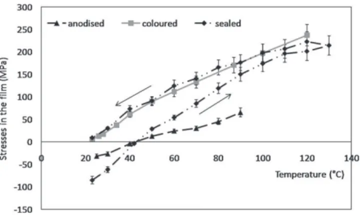
As an example, Fig. 4 represents stresses in a film versus the temperature. Same results were obtained whatever the porosity. The CTE of uncolored and unsealed films was found to be nearly five times lower (5 × 10− 6K− 1) than the aluminium's one confirming previous
works of Alwitt et al.[11] who found the same ratio. In addition, stresses measured once back at ambient temperature are equivalent to residual stresses before heating.
After coloring, the CTE of anodic films is nearly ten times lower than the substrate's one. No modification of residual stresses (at 20 °C) was induced by the test.
During heating and cooling of colored and sealed films, the slope is comparable with the sample colored but not sealed proving that the CTE is not modified by hydration. However, compressive residual stresses are released during the test because dehydration may occur at a temperature over 100 °C[14].
The large difference between CTE of the substrate and the film is leading to tensile stresses in the film during sealing at 100 °C. This loading may explain cases of crazing. Nevertheless, the CTE was not significantly varying with the initial porosity.
3.2.2. Tensile strength
All the coated area was submitted to a uniform deformation at the rupture of the film during bending:
εR= LCah
4ISES
ð3Þ
a and h are defined onFig. 1; ISis the quadratic moment of the sample.
The film was considered purely elastic and its limit tensile stress (σR)
is:
σR= EfεR+ σresidual ð4Þ
Each given value is the average of three different tests.
With increasing porosity, the tensile strength of the anodic film was expected to decrease as described by Ryshkewitch-Duckworth
[15]. In addition, a collapse of the tensile strength of ceramics for porosities between 30 and 50% has been shown by Knudsen et al.[16]
corresponding to the transition from isolated to interconnected porosity.
Fig. 3. Residual stresses measured after each step of the process (anodizing, coloring, sealing) for anodic films with different initial porosities.
Fig. 4. Stress in a film with an initial porosity of 10% as a function of the temperature just after anodizing, after coloring and after sealing.
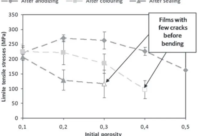
Nevertheless,Fig. 5shows that the tensile strength of uncolored and unsealed films increases for porosities from 10% to 30%, while the strength decreases at higher porosities. The porosity was controlled by changing the anodizing temperature that may change the composi-tion of the anodic film and may explain the increase of limit tensile stress. For porosities higher than 30%, the effects of the porosity become preponderant and the tensile strength decreases.
The limit tensile stress is decreased by the coloring step. The quantity of dyes included in the film increases with the porosity, that explains the more important loss of tensile strength for high porosities. The reaction of precipitation occurring inside pores during dying is[17]:
CoðCH
3COOÞ2þ ðNH4Þ2S→CoS þ 2CH3COONH4 ð5Þ
However, an additional chemical reaction between acetates and the film could explain this weakening. Further tests such as coloring with cobalt nitrates could allow assessing this point.
The hydration of the film enhances this tendency. The transforma-tion occurring during sealing is:
Al2O3þ ðn þ 1ÞH2O→2AlOOH þ nH2OðnN1Þ ð6Þ The resulting hydrated aluminium oxi-hydroxide often looks like a gel having a negligible mechanical resistance. For porosities of 40% and 50%, the film was crazed after the sealing step at 100 °C and therefore measurements are not comparable.
Considering the previous results, at the beginning of the sealing at 99 °C, films with 40% porosity are under tensile thermal stresses of approximately 100 MPa. Added with the tensile residual stresses after coloring (35 MPa), the global stresses in the film are higher than its limit tensile stress (100 MPa).
Thus, the differential thermal dilatations associated with a very low limit tensile stress of highly porous anodic films explains the crazing phenomenon.
3.3. Ageing and flaking
The evolution of the adhesion of the two crazed samples was observed after ageing. Thermal cycling between −80 °C and +80 °C (dwells of 10 min, warming/cooling speed of 10 °C/min) were performed under dried nitrogenous atmosphere. Self-flaking of particles was observed after ageing on samples with 50% porosity.
Scratch-testing was used to compare evolutions of the critical load defined as the lower load provoking a lateral flaking along the scratch
[18]. The critical load is constant for black anodic films with an initial porosity of 40% whatever the number of cycles performed (Fig. 6). Thermal cycles between −80 °C and +80 °C have no impact on the
measured adhesion. On the contrary, a loss of adhesion occurred after the first thermal cycle for samples with an initial porosity of 50%.
The difference of CTE between the film and the substrate results in tensile thermal stresses in the film at temperatures higher than 20 °C. In addition, the water loss of the sample during ageing would result in tensile stresses in the film. Cracks in samples with 50% of initial porosity may propagate under thermal loading resulting in the loss of adhesion observed.
3.4. Numerical simulation
Thermo-mechanical properties of colored and sealed films were used. A thermal load of +80 °C was applied. The influence of the presence of a crack in the film on the variations of interfacial stresses
σint withcrack−σint withoutcrack
σint withoutcrack
! "
is showed onFig. 7.
Two different behaviors depending on the porosity (i.e. elasticity) of the film are observed. For porosities lower than 30%, the presence of a short crack (b13 µm) has no impact on the interfacial stress considered. When cracks become longer (17 µm), the interfacial stress increases. If cracks are long enough, tensile stresses in front of the crack are transmitted by the rigidity of the film until the interface. Interfacial stresses are enhanced.
For films showing porosity higher than 40%, the presence of cracks causes a high deformation of the film with a low increase of stresses (high elasticity). Tensile stresses are in majority transmitted to the more rigid substrate. Interfacial stresses are released.
The width of cracks has always been found to increase during ageing. This suggests that heating during thermal cycling propagates Fig. 5. Tensile strength of the anodic film at each step of the process and depending on
the initial porosity.
Fig. 6. Evolution of the scratch-test critical load with the number of thermal cycles for samples of 40% and 50% of initial porosities.
Fig. 7. Variations of the interfacial stress in the direction of the interface due to the presence of a crack through the porous film at 80 °C.
cracks through the film. However it seems to have a limited impact on the interfacial stresses for high porosity films. The transition between crazing and flaking will be investigated by adding an interfacial crack and observing stress field evolution during thermal cycling. 4. Conclusion and prospects
Initial porosity of films has been proved to largely influence the mechanical behavior of black anodic films. The coloring step results in low tensile residual stresses and decreases the CTE of the film. The film expansion by hydration during sealing results in large compressive stresses. After heating and water desorption, the behavior is the same as a non-sealed film.
Highly porous films have the lower limit tensile stress, affected by coloring and sealing. Combined to tensile stresses induced by the differential thermal dilatations, it results in crazing of highly porous films during sealing.
Ageing between −80 °C and +80 °C has an impact on the adhesion only on samples with an initial porosity of 50%. In this case, the low tensile strength permits the crack propagation during these thermal cycles.
Numerical simulation showed that the presence of cracks is less critical for the interface in highly porous films. Further numerical investigations simulating thermal cycles and including an interfacial crack will be performed to understand the transition between crazing and flaking.
References
[1] Y. Goueffon, L. Arurault, C. Mabru, C. Tonon, P. Guigue, J. Mater. Process. Technol. 209 (11) (2009) 5145.
[2] ESA ECSS-Q-70-03A, Black anodizing of metals with inorganic dyes, 2006.http:// www.ecss.nl.
[3] T. Aerts, Th. Dimogerontakis, I. De Graeve, J. Fransaer, H. Terryn, Surf. Coat. Technol. 201 (2007) 7310.
[4] S.J. Garcia-Vergara, K. El Khazmi, P. Skeldon, G.E. Thompson, Corros. Sci. 48 (2006) 2937.
[5] P. Skeldon, G.E. Thompson, G.C. Wood, X. Zhou, H. Habazaki, K. Shimizu, Corros. Sci. 41 (1999) 291.
[6] G. Yan, J.R. White, Polym. Eng. Sci. 39 (1999) 1866.
[7] R.S. Alwitt, J. Xu, R.C. McClung, J. Electrochem. Soc. 140 (5) (1993) 1241. [8] Y. Goueffon, L. Arurault, S. Fontorbes, C. Mabru, C. Tonon, P. Guigue, Mater. Chem.
Phys., under review.
[9] J.C. Nelson, R.A. Oriani, Corros. Sci. 34 (1993) 307. [10] L. Arurault, Trans. Inst. Met. Finish. 86 (1) (2008) 51.
[11] R.S. Alwitt, R.C. McClung, S. Jacobs, AAIA Technical Papers (A92-31285 12-23) Washington, USA, 1992, p. 39.
[12] R.S. Alwitt, R.C. McClung, Plating Surf. Finish. (1993) 48.
[13] P. Skeldon, G.E. Thompson, G.C. Wood, X. Zhou, H. Habazaki, K. Shimizu, Corros. Sci. 41 (1999) 291.
[14] R.C. Mc Clung, R.S. Alwitt, S. Jacobs, AAIA Technical Papers (A92-31285 12-23) Washington, USA, 1992, p. 46.
[15] W.H. Duckworth, J. Am. Ceram. Soc. 36 (1953) 68. [16] F. Knudsen, J. Am. Ceram. Soc. 42 (1959) 376.
[17] A.K. Sharma, H. Bhojraj, V.K. Kaila, H. Narayanamurthy, Met. Finish. 95 (12) (1997) 14.