HAL Id: hal-02933799
https://hal.univ-grenoble-alpes.fr/hal-02933799
Submitted on 8 Sep 2020
HAL is a multi-disciplinary open access
archive for the deposit and dissemination of
sci-entific research documents, whether they are
pub-lished or not. The documents may come from
teaching and research institutions in France or
abroad, or from public or private research centers.
L’archive ouverte pluridisciplinaire HAL, est
destinée au dépôt et à la diffusion de documents
scientifiques de niveau recherche, publiés ou non,
émanant des établissements d’enseignement et de
recherche français ou étrangers, des laboratoires
publics ou privés.
High Reliability in LoRaWAN
Ulysse Coutaud, Martin Heusse, Bernard Tourancheau
To cite this version:
Ulysse Coutaud, Martin Heusse, Bernard Tourancheau. High Reliability in LoRaWAN. IEEE
Inter-national Symposium on Personal, Indoor and Mobile Radio Communications. PIMRC20., Aug 2020,
London (virtual conference), United Kingdom. �10.1109/PIMRC48278.2020.9217220�. �hal-02933799�
High Reliability in LoRaWAN
Ulysse COUTAUD
Semtech Corporationand LIG CNRS, Grenoble Alps University
Martin HEUSSE
LIG CNRS, Grenoble INP [email protected]
Bernard TOURANCHEAU
LIG CNRS, Grenoble Alps University [email protected]
Abstract—In this paper, we propose to optimize the LoRaWAN®
Adaptive Data Rate algorithm in case an inter-packet error correction scheme is available. We adjust its parameters based on analysis of the LoRa channel, supported by real-world traffic traces. The resulting protocol provides high reliability even over low quality channels with comparable Time on Air and similar downlink usage as the LoRaWAN solution. Simulations and emu-lation fed by real-world channel traces corroborate the analysis. Index Terms—IoT; LoRa; LoRaWAN; LPWAN; QoS; ToA; PDR; FEC; ADR.
I. INTRODUCTION
The Internet of Things (IoT) is a new paradigm for digital communication and wireless networks which opens new op-portunities in terms of applications deployments. But the IoT also comes with new constraints and requirements compared to the legacy technologies. A significant and growing part of these IoT networks is categorized as Low Power Wide Area Networks (LPWAN). LPWANs offer low-throughput connectivity for up to thousands of end-devices sharing the same gateways, with ranges up to several kilometers, very low energy consumption, and low cost for the end-devices transceivers as well as for the infrastructure and maintenance. LoRaWAN, an open network protocol specification developed by the LoRa Alliance® on
top of Semtech’s LoRa® proprietary modulation, is one of
the leading LPWAN technologies [1], [2], [3]. LoRaWAN offers a practical and flexible connectivity solution as a single gateway can handle thousands of end-devices and cover a cell of about ten kilometers radius. Moreover the protocol provides basic mechanisms for dynamic, automatic and over the air management and parameters tuning. Refining these mechanisms is a major means to fully exploit the capabilities of LoRaWAN and improves its reliability while preserving its scalability through a decreased Time On Air. These two aspects are key to support applications development as well as their industrial deployments [4], [5].
The Adaptive Data Rate (ADR) protocol, a key part of LoRaWAN, allows to adjust dynamically the end-device (ED) transmission parameters to adapt to the end-devices transmis-sion conditions or the network load. Appropriate tuning of the LoRaWAN network has potential to improve performance, but the process requires a comprehensive and accurate un-derstanding of the behavior of these networks, in terms of
contention and transmission conditions. Moreover, our work stems from the observation that inter-packet Forward Error Correction (FEC) potentially changes the optimal operating point of the network. With this in mind, this article starts with the analysis and modeling of experimental measurements over a public LoRaWAN network, followed by the proposition of ADRopt, an improved version of the LoRaWAN ADR protocol
which provides high reliability while preserving the network load.
This paper is organized as follow: Section II presents LoRa, LoRaWAN and the ADR. Section III describes the experimental traces database construction and how we use it to emulate packet repetition and FEC. ADRopt is introduced in Section
IV with its performance described in Section V. The state of art is discussed in Section VI.
II. LORA MODULATION ANDLORAWAN
The LoRa modulation [6] uses chirp spread spectrum (CSS) signals to modulate data. A chirp symbol is a linearly increasing frequency ramp mapped cyclically over the radio channel band-width (BW). The information is encoded by the chirp initial frequency offset. The spreading factor (SF) defines the symbol duration, as Tsymbol= 2
SF
BW, and each symbol conveys SF bits.
In the current LoRa implementations, SFs 6 to 12 are available. A higher BW increases frequency spreading but reduces time spreading i.e. the symbol duration, resulting in an increased data rate. A higher SF increases the symbol duration, reduces the data rate and makes the modulation more robust. The inherently robust CSS modulation scheme is complemented by an intra-packet error correcting code with coding rate (CR) between 45 and 48. The LoRa physical layer has a very high link budget of up to 153.5 dB1 and it is robust against noise,
Doppler effect and frequency drift. Changing the transmission parameters (BW, CR, SF) allows to trade robustness (i.e. link budget) for data rate, which is inversely proportional to the time on air for a given packet size.
LoRaWAN [7] is an LPWAN protocol stack build on top of the LoRa [6] physical layer. The network topology is cellular-like with most of the complexity pushed outside of the capillary network. The LoRaWAN gateways (GWs) relay EDs uplink messages to a central network server (NS). EDs are not associated to a particular GW: the GWs forward all
1With Semtech SX1301 chip and 14 dBm PTx. 978-1-7281-4490-0/20/$31.00 © 2020 IEEE.
Personal use of this material is permitted. Permission from IEEE must be obtained for all other uses, in any current or future media, including reprinting/republishing this material for advertising or promotional purposes, creating new collective works, for resale or redistribution to servers or lists, or reuse of any copyrighted component of this work in other works.
the received messages to the NS which handles messages de-duplication, downlink scheduling and routing of uplink data to the application servers. The channel access method is ALOHA [8]: end-devices initiate their transmissions without any kind of coordination. LoRaWAN typically operates in license-free ISM bands in which the transmission power (PTx) and duty cycle
are regulated. In Europe, for instance, LoRaWAN networks mostly use EU868 sub-bands in which the limits are typically a PTx of 14 dBm and a duty cycle of 1%. LoRaWAN is strongly
uplink oriented but each uplink transmission is followed by two short receive windows2 for the reception of ACKs, downlink
traffic or ADR commands (which can all be combined in the same packet). Otherwise, the ED radio remains switched off, which greatly reduces energy consumption. LoRaWAN defines a set of LoRaMAC, commands to manage EDs over-the-air. In particular, these downlink commands allow to adapt the uplink transmission parameters such as PTx, SF and number of
retransmissions (NBTRANS). Many limitations of LoRaWAN in
terms of scalability and effective throughput are inherent to its ALOHA access [4], [5]. Moreover, LoRaWAN reliable uplink traffic handling is very limited by its downlink traffic capacity [5], [9], even though improvements are possible [10].
The ADR is an algorithm part of LoRaWAN to adapt the EDs transmission parameters over the air. With the ADR, the NS estimates the link quality by monitoring the uplink packets metadata and it adapts periodically the ED transmission parameters via LoRaMAC, commands sent in its rare downlink communication opportunities with the ED. If no downlink packet is received for too long, the ED increases its PTx
and its SF to try to regain connectivity. The ADR-ED and ADR-NS algorithms appear respectively in Algorithm 1 with Semtech’s implementation3 on the ED side and Algorithm 2 from The Things Network4 (TTN) on the server side. This protocol addresses the following three questions by adjusting its internal parameters:
• How frequently does the ED require a downlink from the NS? ACK LIMIT and ACK DELAY bound the acceptable number of consecutive uplinks without an ACK command reception. The default recommended values are ACK LIMIT=64 and ACK DELAY=32 transmissions.
• How does the NS estimate link quality? ADRTTN takes
the SNR maximal value from the last twenty received LoRaWAN packets. Even if this maximal value tends to over-evaluate the channel SNR, it is less dependent on the Packet Error Rate (PER) than the average, because one expects that the transmissions facing more attenuation are more likely to be missed. Note that this estimation does not take into account the reception by multiple gateways, and neither packet retransmissions5, both of which tend to
increase the estimated SNR.
2The ED might open additional receive windows if specified in class B Beacon and class C Continuously open receive windows.
3Version 1.0.3 github.com/Lora-net/LoRaMac-node [11]. 4github.com/TheThingsNetwork/lorawan-stack
5For a given received LoRaWAN packet only the best SNR value is kept.
Algorithm 1 ADR-ED algorithm. 1: ACK LIMIT=64; ACK DELAY=32; 2: ACK CNT=ACK LIMIT; ACK Req=false; 3: NBTRANS =3; PTx =PTxmax; SF=12;
4: while (true) do
5: if (ACK CNT >= ACK LIMIT) then 6: ACK Req=true;
7: end if
8: if (ACK CNT==ACK LIMIT+ACK DELAY) then 9: PTx =PT xmax ; increaseSF();
10: ACK CNT = ACK LIMIT; 11: end if
12: waitTxRequest(); TxSend(ACK Req); 13: if (RxReceived()) then
14: applyRxADRCommand(); ACK Req=false; ACK CNT = 0;
15: else
16: ACK CNT++; 17: end if
18: end while
• How conservative should the transmissions parameters selection by the NS be? The MARGIN parameter biases the algorithm towards more robust transmission, at the expense of channel occupancy. The default value is 15dB.
III. TRANSMISSION TRACES COLLECTION AND ANALYSIS We built an experimental data-set by recording LoRaWAN transmissions towards several gateways. We then used the recorded packet series to replay and show the influence and potential gain of different ADR strategies.
A. Setup and experiment
The test-bench consists of one indoor ED6, placed on the third floor of a residential building and connected to TTN7 through a set of gateways. The device transmits series of LoRaWAN packets with various parameters. The series cor-respond to the different (PTx, SF) couple, representing the 48
possible combinations8. The experiment ran for a whole week
and there is on average 4300 packets transmission attempts per series, or one packet every ≈ 2.4 minutes with a 15 bytes LoRaWAN payload. We used three channels centered on 868.1, 868.3 and 868.5 MHz. The transmission parameters were randomized in order to avoid shadow correlations and congested frequency channels. Eight TTN GWs showed up within the transmission range of the device. This represents a total of 48×8 = 348 independents LoRaWAN series of packets. This set of measures captures the patterns of packet erasure over
6B-L072Z-LRWAN1 LoRa/Sigfox Discovery kit 7thethingsnetwork.org
Algorithm 2 ADR-NS algorithm. 1: MARGIN=15;
2: PDRHigh =95%;PDRMed =90%;PDRLow =70%;
3: while true do
4: ACK Req=waitRx(); 5: if (ACK Req) then
6: SNRmeasured = History20packets.getSNRMax();
7: SNRfloor = −(7.5 + (SF − 7) × 2.5)+ MARGIN;
8: SNRmargin = SNRmeasured - SNRfloor
9: if (nbPacketsReceived<20) then
10: SNRmargin − = 2.5;
11: end if
12: while (SNRmargin>2.5 && SF>7) do
13: SNRmargin − = 2.5;
14: PTx =PT xmax;
15: SF−−;
16: end while
17: while (SNRmargin>2.5 && SF==7) do
18: SNRmargin − = 2.5;
19: PT x− −;
20: end while 21: end if
22: PDR = History20packets.getPDR(); 23: if (PDR > PDRHigh) then
24: NBTRANS = max(1,NBTRANS-1)
25: else if (PDRMed ≥ PDR > PDRLow) then
26: NBTRANS = min(3,NBTRANS +1)
27: else if (PDRLow≥ PDR) then
28: NBTRANS = 3;
29: end if 30: end while
a typical LoRaWAN network deployed in the Grenoble urban area9, and it is publicly available10.
B. Results Analysis
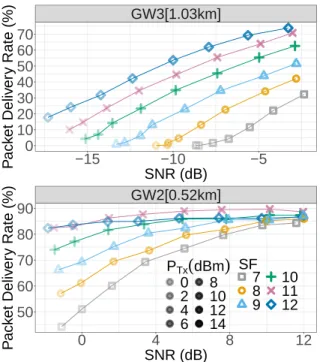
The experimental data set allows for some propagation model characterization. For all GWs, SNR increases with PTx and
this in turn improves the PDR until this latter reaches a ceiling which depends on the propagation channel quality, i.e. the GW location. For instance this ceiling is ≈ 85% for GW{2, 5} and is apparent for GW2 in Fig.1.
A higher SF increases the PDR and this improvement is obvious for low to medium-low SNR. For example, in Fig. 1, the PDR of GW3 with PTx=14 dBm jumps from 32% to 74%
when switching from SF7 to SF12. However, when the received signal power (PRx) is strong enough, a higher SF may not
provide a better PDR and a significant fraction of the packets is lost even when the SNR is high. See for example GW2 in Fig. 1 with the SNR between -2.5 and 12.5 dB, all PDR series converge to similar values. We also point the fact that 9Seven GWs within a 4 km range of the ED and one at 14km with a 1200m higher elevation. 10gricad-gitlab.univ-grenoble-alpes.fr/coutaudu/lora-measurements GW3[1.03km] −15 −10 −5 0 10 20 30 40 50 60 70 SNR (dB) P ack et Deliv er y Rate (%) GW2[0.52km] 0 4 8 12 50 60 70 80 90 SNR (dB) P ack et Deliv er y Rate (%) PTx
(
dBm)
0 2 4 6 8 10 12 14 SF ● 7 8 9 10 11 12Fig. 1. Experimental PDR as a function of estimated SNR for GW2 and GW3.
for GW{2}, SF10 and SF11 lead to a better PDR than SF12 for high SNR. We believe this comes from congestion due to an over-usage of SF12 with packets having a large ToA footprint. Also, GW1, only a few meters from the device, still presents a few percents of residual errors even with a very high SNR. Hence, the reception PDR has typically a ceiling around 85% for most GWs, which matches the expected behavior of Rayleigh multi-path fading channel as suggested in a previous study [12]. This would also correspond to our test-bench without any LoS between the ED and GWs. Following this model, PRx is exponentially distributed [13] with a probability
distribution function: PDF(PRx) = e
(−PRxB )
B where B is the
average PRx. Over such a Rayleigh fading channel, a significant
fraction of transmission faces very challenging conditions. Appropriate tuning of the SF and PTx is thus fundamental
to obtain connectivity with a reasonable PDR, but it is not sufficient to establish a highly reliable channel. In other words, increasing PTx improves PRx, but beyond a certain threshold,
the SNR gain will not bring much PDR improvement. Besides, increasing the transmission power will create interference for EDs located further away. A higher SF increases sensitivity and link budget but might not improve PDR because of the ceiling and collisions as described above. Hence, it is hopeless to only rely over PTx and SF increases to provide a highly reliable
LoRaWAN channel.
C. Replaying real-world traces
We use our real-world packet erasure series to emulate two MAC-layer QoS mechanisms for LoRaWAN, in order to better understand their limits and assess their performance. On the one hand, we consider systematic retransmissions implemented
in LoRaWAN [7] and on the other hand, the FEC protocol described in [14].
1) Blind repetitions: The results with this simple mechanism appear in Fig.2 with the Data Delivery Rate (DDR), the ratio of data effectively delivered to the application layer, as a function of the PDR for a number of retransmissions of each packet NBTRANS, between 1 and 32. The first two retransmissions, i.e
NBTRANS respectively 2 and 3, lead to a high gain in DDR
over medium quality channels. For instance, over a 40% PDR channel, switching to 2 or 3 retransmissions improves the DDR to more than 60% and 75% respectively. But the DDR gain for a channel with and already high PDR is small, because most of the data is already delivered. Beyond 3 retransmis-sions, the DDR improvement brought by each retransmission lessens. Moreover, reaching high reliability needs a lot of retransmissions and is ineffective for low quality channels. For instance, even with NBTRANS =32, DDR>99% is only reached
when PDR>30% because of the presence of bursts of erasures, which are difficult to correct via blind repetitions. We conclude that systematic retransmissions are insufficient to reach high reliability in LoRaWAN.
Fig.3 plots the DDR, for series of packets with SF and
NBTRANS such that their ToA is equivalent, as a function of
PTx. This shows the complementarity of the SF and NBTRANS
parameters to reach the best DDR for a given time budget. However, when the GW is far, high SF and few retransmissions provide the better DDR because the GW is simply out of range at lower SF. When the GW is in a reasonable range for lower SF, the tendency is quickly inverted and low SF with several retransmissions provides better DDR. Thus, this result calls for a smart response against Rayleigh channels to avoid a counter-productive increase of SF or NBTRANS.
● ● ● ● ● ●●●●●●●●●●●●●●●●●●●●●●●●●●●●●●●●●●●●●●●●●●●●●●●●●● ●●●●●●●●●●●●●●●●●●●●●● ● ●●●●●●●●●●●● ●●●●● ● ●●●●●●●●●●●●●● ●●●●●● ●●●●●●●●●●●●● ●●●●● ● ●●●●●●●●●●●●●●●●●● ● ●●●●●●●●●●●●● ●●●●●●●●●●●●●● ● ●●●●●●●●●●●●●●●●●● ●●●●●●●●●●●●●●●●●●●●●●●●●●●●●●●●●●●●●●●●●●●●●●●●●●●●●●●●●●●●●●●●●●●●●●●●●●●●●●●●● ●●●●●●●●●●●●●●●●●●●●●●●●●●●●●●●●●
0
25
50
75
100
0
25
50
75
100
Packet Delivery Rate (%)
Data Deliv
er
y Rate (%)
NB
TRANS ●1
2
3
4
6
8
16
32
Fig. 2. Experimental DDR against PDR for several NBTRANS. 2) Inter-packet FEC: FEC is widely used in wireless dig-ital communication. High reliability in LoRaWAN can be achieved by the use of Reed-Solomon codes but requires additional periodic downlinks [15]. Another approach using linear combination without downlinks was proposed [16] but
● ● ● ● ● ● ● ● GW3[1.03km] 0 2 4 6 8 10 12 14 0 25 50 75 100 PTx
(
dBm)
Data Deliv er y Rate (%) SFxNBTRANS ● SF07x32 SF08x16 SF09x8 SF10x4 SF11x2 SF12x1Fig. 3. Experimental DDR against PTxfor several equivalent ToA.
with discrepancies between analysis and experimental results. This idea is improved in another work [14] which gives details for a production code implementation including data fragmentation/reassembly, and provides results corroborating the analysis.
Fig.4 shows that a FEC with coding rate 12 provides high reliability with DDR>95% as long as the PDR is above 60%. Below this threshold, the DDR quickly drops to match the channel native PDR at around 40%. The comparison with the case of one retransmission, i.e NBTRANS = 2, is favorable only
below 55% PDR. Thus, from a DDR perspective, a mix of the two QoS strategies would be effective and we discuss this in Section IV. ● ● ● ● ● ● ● ● ● ● ● ● ● ● ● ● ● ● ● ● ● ● ● ● ●● ● ● ● ● ●● ● ● ● ● ●●● ● ● ● ● ●●● ● ● ●●●●●● ●●●●●● ●● ●● ●● ● ● ● ● ●● ● ● ● ● ●● ● ● ● ● ●● ● ● ● ● ●● ● ● ● ● ●● ● ● ● ● ● ● ● ● ● ● ● ● ● ● ● ● ● ● ● ● ● ● ● ● ●● ● ● ● ● ●●● ● ●● ● ●●● ● ● ● ● ●● ● ● ● ●● ●●●●●● ●●●●●● ●●●●●●●●●●●●●●●●●●●●●●●● ●●●●●● ●●● ● ● ● ●●● ● ● ● ● ● ● ● ● ● ● ● ● ● ● ● ● ● ● ● ● ● ● ● ● ●● ● ● ●● ●●● ● ● ● ●●● ● ● ● ●● ● ● ● ● ●● ● ● ● ● ●●●● ● ● ● ●●●● ● ● ● ●●●● ● ● ● ●●● ● ● ● ● ●● ● ● ● ● ●● ● ● ● ● ● ● ● ● ● ● ● ● ●● ● ● ● ● ●●● ● ● ● ● ●●● ● ● ● ●●●● ● ● ● ● ●●● ● ● ● ●●● ● ● ● ● ●● ● ● ● ● ●● ● ● ● ● ●● ● ● ● ● ●● ● ● ● ● ● ● ● ● ● ● ● ● ● ● ● ● ● ● ● ● ● ● ● ●
0
25
50
75
100
0
25
50
75
100
Packet Delivery Rate (%)
Data Deliv
er
y Rate (%)
● ●FEC
cr
=1/2
NB
TRANS=2
Fig. 4. Experimental DDR with FEC versus Retransmission with equivalent ToA.
IV. IMPROVINGADAPTIVEDATARATE
Based on the insights gained in the above section, we have designed ADRopt, an improved version of ADR. It consists
in a precise computation of the ADR algorithm’s parameters, MARGIN, PDRHigh, PDRMed, PDRLow, for LoRaMAC, using
FEC and retransmissions. We first turn our attention to eval-uating the DDR degradation due to the channel overload of retransmissions.
ln
(
−1+ 5 2)
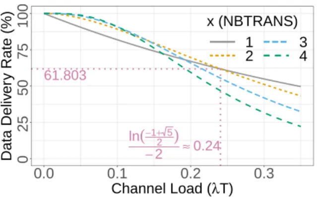
−2 ≈0.24 61.803 0 25 50 75 100 0.0 0.1 0.2 0.3 Channel Load (λT) Data Deliv er y Rate (%) x (NBTRANS) 1 2 34Fig. 5. ALOHA DDR against load for multiples transmissions.
Considering (unslotted) ALOHA access without capture ef-fect [8], DDR over the channel is defined as P (λT ) = e−2λT where λ is the Poisson process intensity —the number of packets generated per second— and T is the average frame duration. The formula extends to x retransmissions with
P (x, λT ) = 1 − (1 − (e−2xλT))x.
This leads to P (2, λT ) ≥ P (1, λT ) > 0.6 for λT ≤
log(−1+
√ 5 2 )
−2 ≈ 0.24.
We saw in Section III-C that applying FEC over a 60% PDR channel provides high reliability. Also, x > 2 only provides DDR improvement over a low load channel and otherwise, performances quickly drops, as illustrated in Fig.5 with P (x, λT ) computations. Thus, ADRopt should operate
mainly with NBTRANS =2, with fluctuation up to 3 and down to
1 when the channel is either highly degraded or of high quality. Hence, the FEC will eventually operate with high enough PDR and provide very high DDR. Moreover, with this new protocol, PDRHigh, PDRMed, PDRLowcan be set to respectively 90%, 70%
and 30%, which reduces the overall ToA.
Assuming a Rayleigh channel for LoRa, then the SNR follows an exponential distribution with cumulative distribution function, F (x) = 1 − e−x(and its inverse F−1(x) = −log(1 − x)). We can compute F−1(0.91/60) ≈ 6.3 ≈ 10108, which
means that there is 90% chances for the last 60 packets’ maximal SNR to be less than 8 dB over the mean SNR. Notice that the NS estimates the link quality by taking the maximal SNR over the last 20 received packets without taking into account retransmissions or losses. Hence, the effective sample’s size increases with NBTRANSand packet losses. Finally, 60 is an
acceptable tradeoff for the number of packets used for the link quality estimation, in the case NBTRANS =2 and P DR ≈ 70%.
Also, F−1(0.61/2) = 1 = 0 dB, i.e, 0 dB is the SNR threshold
such that 60% of packets are received with NBTRANS =2. So,
MARGIN= 8 dB is a good approximation for DDR > 60% with NBTRANS =2, as it gives minimum ToA. Eventually, this
DDR is enough for the FEC to recover the remaining erasures as shown in Section III-C2.
When the NS receives too few packets, instead of introducing
extra margin, it just waits for a minimum of 5 received packets before answering the ED. Without loss of generality, we disabled the power control as it only keeps PTx to its max
unless SNR is strong enough and SF is already minimal which corresponds to unavailable data rate (SF7 GW250kHz or SF6).
V. PERFORMANCE COMPARISON
We show ADRopt performances over a simulated Rayleigh
channel and by replaying our experimental series. For sim-plicity, we assume a perfect downlink channel which allows to transmit all the ADR commands. The payload’s overhead produced by the FEC redundancy is piggybacked into existing packets and so, the LoRa payload increases from 28 to 50 bytes11. Note that the packet size has little impact on the reception’s success [12] and so, we do not consider any recep-tion rate penalty for longer packets. The simulated Rayleigh channel is a serie of packets with a fixed SNR mean (SN R), which correspond to fixed positions of the ED and the gateway. For each packet p, SN Rp = SN R × X where X is a unit
mean exponential probability density function. Thus, a packet is dropped if SN Rp< SN Rfloor. We simulate it for SN R in
[-30 dB, 10 dB] by steps of 0.5 dB with series of 5000 packets repeated 50 times. We compared DDR and ToA of ADRopt
and ADRTTN over a simulated Rayleigh channel with various
number of GW in range.
ADRopt sharply adapts the transmission parameters and
reaches DDR > 98% over a channel with SN R > −21.5 dB. This corresponds to SF12 with FEC and NBTRANS =3, sort
of ”Maximal Effort” policy result in this context. However, ADRopt’s ToA is higher than ADRTTN’s for channel with
SN R ≤ −17 dB. This corresponds to the extra energy in-vested by ADRopt to achieve a reliable communication. For
channel with SN R > −17 dB, the transmissions parameters of ADRopt are more accurate and thus reliability is obtained
with lower ToA.
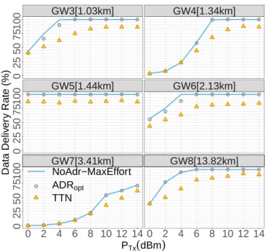
The results derived from our real world traces of trans-missions shown in figures 6 and 7, confirm the simulations: ADRopt provides adequate tuning for the transmissions and
either DDR > 98% is achieved or a most robust available configuration is used. Except for GW7, DDR > 98% is reach for every GW with PT x> 6 dBm. However, in some rare cases
(for GW 3 and 6 at PTx2 and 4 dBm), ADRoptslightly
under-performs because the variations of the channel conditions are faster than the adaptation rate.
VI. STATE OF THE ART A. Adaptive Data Rate
Various studies evaluate and improve the ADR’s perfor-mances. But because the algorithm is not strictly defined by the LoRaWAN specification, various implementations exist and variations of their interpretation appear in the literature. Some 1113 (LoRaWAN headers) + 15 bytes to 13 + 1 + (15 + 3) × 2 = 37 bytes of payload respectively without and with FEC.
● ● ● ● ● ● ● ● ● ● ● ● ● ● ● ● ● ● ● ● ● ● ● ● ● ● ● ● ● ● ● ● ● ● ● ● ● ● ● ● ● ● ● ● ● ● ● ● GW7[3.41km] GW8[13.82km] GW5[1.44km] GW6[2.13km] GW3[1.03km] GW4[1.34km] 0 2 4 6 8 10 12 14 0 2 4 6 8 10 12 14 0 25 50 75 100 0 25 50 75 100 0 25 50 75 100 PTx
(
dBm)
Data Deliv er y Rate (%) NoAdr−MaxEffort ● ADRopt TTNFig. 6. Real world series of packets, DDR for various GW.
● ● ● ● ● ● ● ● ● ● ● ● ● ● ● ● ● ● ● ● ● ● ● ● ● ● ● ● ● ● ● ● ● ● ● ● ● ● ● ● ● ● ● ● ● ● ● ● GW7[3.41km] GW8[13.82km] GW5[1.44km] GW6[2.13km] GW3[1.03km] GW4[1.34km] 0 2 4 6 8 10 12 14 0 2 4 6 8 10 12 14 0 25 50 75 100 0 25 50 75 100 0 25 50 75 100 PTx
(
dBm)
Time On Air NoAdr−MaxEffort ● ADRopt TTNFig. 7. Real world series of packets, ToA normalized against no FEC, SF7 and NBTRANS=1, for several GW.
studies [17], [18] suggest that the ADR-NS algorithm (Algo-rithm 2) tends to overestimate the link quality because of the MAX operator used for the SNR estimation. As a consequence, they suggest to replace it by a MEAN operator. But because the packets with lowest SNR are likely to be more censored, the current path loss’ estimation can be biased by both MEAN and MAX. Moreover, the SNR variance has a major influence on the ADR’s operation [18]. We think that the SNR distribution pattern and parameters estimation as described in Section IV are key for optimized ADR decisions.
The ADR algorithm can be replaced by a load-balancing algorithm to minimize contention on a single cell LoRaWAN network [19]. This approach increases overall throughput but this may come at the cost of decreasing the network’s reliability. An algorithm to select adequate LoRa transmissions parameters to achieve a given reliability between one transmitter and one receiver while reducing energy consumption has been proposed [20]. It starts from the most robust setting and evolves towards a satisfactory setting after the transmission of a few hundreds probes while temporal dynamics are handled by regular restarts. All of this makes it impractically slow compared to our needs. B. LoRa/LoRaWAN link characterization
The quality of a signal reception, and so the data transmission success, is determined by: the gain of the system which corresponds to PTx and the antennas gains, the large scale
fading (LSF) which depends on the distance between the radios and the propagation medium path loss exponent, the shadow fading (ShF) which corresponds to obstructions over the main path, the small scale fading (SSF) which corresponds to the gain from multi-path propagation, the ambient noise, interference, temporal changes of the propagation medium, fast shadowing due to movements around the receiver and transmitter. Charac-terizing a radio channel consists in providing models for these components. We consider a context with static EDs and GWs where LSF and ShF are fixed in time and so we are specifically interested on SSF characterisation and modeling. Thanks to LoRa and LoRaWAN academic and industrial interest, many experimental measurements are reported in the literature.
The monitoring of the 868MHz ISM radio band in a medium sized city in Denmark at street level [21] gives insight into the interference that LoRa may face. It shows that a LoRa channel may experience highly heterogeneous interference patterns, both in periodicity and strength of the colliding signals, even with close distances.
Many studies focus on LoRa link characterization. Some ex-perimental measurements of LoRa link in outdoor environment [22], [16], [23] focus mainly on LSF but provides insight into the PRxvariation: they find a standard deviation of respectively
8 dB, 7.1 dB and between 6.9 dB and 11.2 dB. Notice that among these studies, only one of them takes into account the bias in the data due to the low receive power packets censorship [23]. Another experimental study of the LoRa link characterization over a public LoRaWAN network in a medium sized city [12] shows that the packet’s size has relatively small
impact on the reception rate and highlight the impact of an initial successful synchronization probability. The behavior of their experimental channel SNR distribution seems to follow a truncated exponential distribution which is expected from a censored Rayleigh channel, like we use in our analysis of Section IV. LoRa can also be subject to periodic variation of the link quality: an experimental study exposes a periodic 20 dB fading over a 10km LoRa transmissions that may be caused by daily variation of the air’s refraction index combined to multi-path propagation [24].
An experimental study of the LoRa indoor path loss in multi-floor buildings, mainly focused on LSF and ShF, provides some insight into SSF: up to 20 dB variation might be encountered because of people’s movement [25]. Notice that the SSF measurement is fit into a Rician distribution, corresponding to multi-path propagation with a dominant path, but this result is to be taken carefully since it is the signal’s envelope, and not the received power, that is expected to follow Rician distribution [26], [13]. Similarly, SSF measurement is compared to a Rayleigh distribution. Again, the Rayleigh distribution corresponds to the expected signal envelope’s distribution in the case of multi-path without dominant path. In this case, the received power is expected to be exponentially distributed [13]. However, no information is given on the packet loss during the SSF measurement and a censored data set might results in false positive distribution model fitting as we discuss in Section III. However, the fact that the people’s movement highly increases the LoRa SSF is also briefly confirmed by another experimental study [27].
VII. CONCLUSION
From experiments and models, ADRopt proposes large
op-timizations of the LoRaWAN ADR using LoRaMAC, FEC and carefully computed parameters. ADRoptsoftware protocol
successfully provides high reliability, with DDR > 98% in LoRaWAN networks even over low quality channels. The proposition is validated both by simulation and experimental channel transmissions replays. Moreover, ADRopt employs no
more additional downlinks than the legacy LoRaWAN ADR. ADRopt’s Time on Air is bounded by the maximal effort
configuration which advocates for its scalability and makes it realistic for real life deployment. Another benefit of this research is its accurate LoRa channel characterization study in an urban environment by a Rayleigh multi-path propagation model.
Our future work will extend ADRopt with accurate handling
of multiple gateway cell, and its integration with load-balancing algorithms that better tackle contentions.
REFERENCES
[1] L.Vangelista, A. Zannella, and M.Zorzi, “Long-range IoT technologies: the dawn of LoRa,” in Future Access Enablers for Ubiquitous and Intelligent Infrastructures, 2015.
[2] O. Khutsoane, B. Isong, and A. M. Abu-Mahfouz, “IoT devices and applications based on LoRa / LoRaWAN,” in IECON 2017-43rd Annual Conference of the IEEE Industrial Electronics Society. IEEE, 2017.
[3] K. Mekki, E. Bajic, F. Chaxel, and F. Meyer, “A comparative study of LPWAN technologies for large-scale IoT deployment,” ICT express, 2019. [4] O. Georgiou and U. Raza, “Low power wide area network analysis: Can LoRa scale?” IEEE Wireless Communications Letters, vol. 6, no. 2, pp. 162–165, 2017.
[5] F. Adelantado, X. Vilajosana, P. Tuset-Peiro, B. Martinez, and J. Melia, “Understanding the limits of LoRaWAN,” IEEE Communications, vol. 55, no. 9, 2017.
[6] Semtech Corporation, “LoRa Modulation Basics,” ”https://lora-alliance. org/lorawan-for-developers”, Tech. Rep. AN1200.22, 2015.
[7] N.Sornin and A.Yegin, “Lorawan 1.0.3,” ”https://lora-alliance.org/ resource-hub/lorawanr-specification-v103”, LoRa Alliance, Tech. Rep., 2018.
[8] N. Abramson, “Development of the ALOHANET,” IEEE Trans. Inf. Theor., vol. 31, no. 2, 2006. [Online]. Available: http://dx.doi.org/10. 1109/TIT.1985.1057021
[9] A.-I. Pop, U. Raza, P. Kulkarni, and M. Sooriyabandara, “Does bidi-rectional traffic do more harm than good in LoRaWAN based LPWA networks?” in Global Communications (GLOBECOM). IEEE, 2017. [10] V. Di Vincenzo, M. Heusse, and B. Tourancheau, “Improving downlink
scalability in LoRaWAN,” in International Conference on Communica-tions (ICC). IEEE, 2019.
[11] LoRa Alliance, “LorawanT M 1.0.3 revision A regional parameters,” ”https://lora-alliance.org/sites/default/files/2018-07/lorawan regional parameters v1.0.3reva 0.pdf”, Tech. Rep., 2018.
[12] T. Attia, M. Heusse, B. Tourancheau, and A. Duda, “Experimental Characterization of LoRaWAN Link Quality,” in Global Communications Conference (GLOBECOM). IEEE, 2019. [Online]. Available: https: //hal.archives-ouvertes.fr/hal-02316402
[13] A. Goldsmith, Wireless communications. Cambridge university press, 2005.
[14] U. Coutaud, M. Heusse, and B. Tourancheau, “Fragmentation and forward error correction for LoRaWAN small MTU networks,” in EWSN ws Massive LoRa Deployments: Challenges and Solutions (MaDeLoRa). IEEE, 2020.
[15] U. Coutaud and B. Tourancheau, “Channel coding for better QoS in LoRa networks,” in Wireless and Mobile Computing, Networking and Communications (WiMob). IEEE, 2018.
[16] P. J. Marcelis, V. Rao, and R. V. Prasad, “DaRe: Data recovery through application layer coding for LoRaWAN,” in Internet-of-Things Design and Implementation. ACM, 2017.
[17] V. Hauser and T. H´egr, “Proposal of adaptive data rate algorithm for LoRaWAN-based infrastructure,” in Future Internet of Things and Cloud (FiCloud). IEEE, 2017.
[18] M. Slabicki, G. Premsankar, and M. Di Francesco, “Adaptive config-uration of LoRa networks for dense IoT deployments,” in Network Operations and Management Symposium (NOMS). IEEE/IFIP, 2018. [19] S. Kim and Y. Yoo, “Contention-aware adaptive data rate for throughput
optimization in LoRa wan,” Sensors, vol. 18, no. 6, 2018.
[20] M. Bor and U. Roedig, “Lora transmission parameter selection,” in Distributed Computing in Sensor Systems (DCOSS). IEEE, 2017. [21] M. Lauridsen, B. Vejlgaard, I. Z. Kov´acs, H. Nguyen, and P. Mogensen,
“Interference measurements in the european 868 mhz ism band with focus on LoRa and sigfox,” in 2017 IEEE Wireless Communications and Networking Conference (WCNC). IEEE, 2017, pp. 1–6.
[22] J. Petajajarvi, K. Mikhaylov, A. Roivainen, T. Hanninen, and M. Pet-tissalo, “On the coverage of LPWANs: range evaluation and channel attenuation model for LoRa technology,” in ITS Telecommunications (ITST). IEEE, 2015.
[23] G. Callebaut and L. Van der Perre, “Characterization of LoRa point-to-point path-loss: Measurement campaigns and modeling considering censored data,” IEEE Internet of Things Journal, 2019.
[24] T. Ameloot, P. Van Torre, and H. Rogier, “Periodic LoRa signal fluctua-tions in urban and suburban environments,” in European Conference on Antennas and Propagation (EuCAP). IEEE, 2019.
[25] W. Xu, J. Y. Kim, W. Huang, S. Kanhere, S. Jha, and W. Hu, “Measure-ment, characterization and modeling of LoRa technology in multi-floor buildings,” IEEE Internet of Things Journal, 2019.
[26] J. D. Parsons, The mobile radio propagation channel. Wiley, 2000. [27] T. Ameloot, P. Van Torre, and H. Rogier, “A compact low-power LoRa
IoT sensor node with extended dynamic range for channel measurements,” Sensors, vol. 18, no. 7, 2018.