HAL Id: hal-02484255
https://hal.archives-ouvertes.fr/hal-02484255
Submitted on 19 Feb 2020
HAL is a multi-disciplinary open access
archive for the deposit and dissemination of
sci-entific research documents, whether they are
pub-lished or not. The documents may come from
teaching and research institutions in France or
L’archive ouverte pluridisciplinaire HAL, est
destinée au dépôt et à la diffusion de documents
scientifiques de niveau recherche, publiés ou non,
émanant des établissements d’enseignement et de
recherche français ou étrangers, des laboratoires
Multi-resonant silicon nanoantennas by evolutionary
multi-objective optimization
Peter Wiecha, Arnaud Arbouet, Aurélie Lecestre, Guilhem Larrieu, Vincent
Paillard
To cite this version:
Peter Wiecha, Arnaud Arbouet, Aurélie Lecestre, Guilhem Larrieu, Vincent Paillard. Multi-resonant
silicon nanoantennas by evolutionary multi-objective optimization. Computational Optics II, May
2018, Frankfurt, Germany. pp.1069402, �10.1117/12.2315123�. �hal-02484255�
Multi-resonant silicon nanoantennas by evolutionary
multi-objective optimization
Peter R. Wiecha
a, Arnaud Arbouet
a, Christian Girard
a, Aurélie Lecestre
b, Guilhem Larrieu
b,
and Vincent Paillard
aa
CEMES, Université de Toulouse, CNRS, Toulouse, France
b
LAAS, Université de Toulouse, CNRS, INP, Toulouse, France
ABSTRACT
Photonic nanostructures have attracted a tremendous amount of attention in the recent past. Via their size, shape and material it is possible to engineer their op-tical response to user-defined needs. Tailoring of the optical response is usually based on a reference geom-etry for which subsequent variations to the initial de-sign are applied. Such approach, however, might fail if optimum nanostructures for complex optical responses are searched. As example we can mention the case of complex structures with several simultaneous opti-cal resonances. We propose an approach to tackle the problem in the inverse way: In a first step we define the desired optical response as function of the nanos-tructure geometry. This response is numerically evalu-ated using the Green Dyadic Method for fully retarded electro-dynamical simulations. Eventually, we optimize multiple of such objective functions concurrently, us-ing an evolutionary multi-objective optimization algo-rithm, which is coupled to the electro-dynamical sim-ulations code. A great advantage of this optimization technique is, that it allows the implicit and automatic consideration of technological limitations like the elec-tron beam lithography resolution. Explicitly, we opti-mize silicon nanostructures such that they provide two user-defined resonance wavelengths, which can be indi-vidually addressed by crossed incident polarizations.
1. INTRODUCTION
In the last decades, properly designed photonic nanos-tructures have been used to control light at the sub-wavelength scale.1 With an appropriate choice of ma-terial, particle shape and size, it is possible to tailor many optical effects such as resonant scattering (e.g. for color rendering),2,3directionality4,5or polarization of scattered light,6nano-scale heat generation7or non-linear optical effects.8–10 In this context, high-index dielectric nanostructures have attracted particular in-terest owing to their capacity to generate strong electric Further author information: (Send correspondence to P.R.W.)
E-mail: [email protected]
and magnetic fields with very low non-radiative dissipa-tive effects.11–15 Resonances in dielectric nanoparticles are spectrally tunable from the UV to the near IR.16,17 Conceiving photonic nanostructures is usually based on a reference geometry, chosen by intuitive consider-ations. The reference structure is then systematically adapted along a few free parameters in order to op-timize its optical response to a given problem. If we consider more complex models, due to the increasing number of free parameters, the systematic analysis of the whole parameter-space can quickly become an im-possible task and trial-and-error is usually not an ef-ficient strategy neither. Heuristic techniques such as Evolutionary Optimization (EO) can be a better ap-proach to this kind of problems.18 EO mimics natu-ral selection processes in order to drive a solution to a complicated problem to its global optimum. While radio-frequency antenna design uses EO techniques al-ready for several decades, in nano-photonics evolution-ary methods are employed only for a couple of years. Some remarkable success has been reported in the de-sign of single-particle geometries for the maximization of near-field intensities,19–22in far-field scattering from plasmonic particles,23–25 for structural color26or in the design of hybrid plasmonic/dielectric nanostructures.27 Evolutionary strategies have also been used to conceive larger structures like assemblies of several tens to hun-dreds of nano-particles,28 photonic crystal waveguides and metasurfaces29,30 or even complex nano-photonic devices.31,32 One major advantage of evolutionary opti-mization of nanostructure geometries is the possibility to include fabrication constraints in the problem de-scription, hence automatically yielding experimentally feasible structures.33,34
The above cited works target single-objective prob-lems. This is the simplest case of an optimization scenario in nano-optics. A nano-structure that con-currently fulfills multiple objectives will be in general more difficult to design. To this end, particular algo-rithms exist for evolutionary multi-objective optimiza-tion (EMO).35 Examples from recent literature are the automated design of multi-resonant silicon nanostruc-tures,33the optimization of a metasurface with multiple
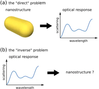
(a)
the "direct" problem(b)
the "inverse" problemnanostructure optical response
wavelength scatt ering optical response wavelength scatt ering nanostructure ?
Figure 1. Illustration of both (a) direct and (b) inverse problems in nano-optics. The direct problem is the calcula-tion of the optical response of a given nanostructure. The inverse problem, on the contrary, consists in searching a specific particle geometry which fulfills some desired optical response.
focal spots,36or the EMO-driven design of a plasmonic waveguide which has an optimum robustness against geometrical variations.37
In this proceedings, we present a combination of EMO with the Green Dyadic Method (GDM) for fully retarded electro-dynamical simulations.38–40 We dis-cuss two different approaches to multi-objective opti-mization. In the first, we use a multi-objective fitness function and optimize it using single-objective algo-rithms. In the second approach, we optimize all ob-jectives concurrently via a Pareto optimization. We demonstrate both methods at the example of silicon nanoantennas, which are optimized to yield an optical response defined by two objectives.
2. INVERSE PROBLEMS IN
NANO-OPTICS
Calculating the optical properties of photonic nanos-tructures with defined geometry and known material is a relatively straightforward problem. Manifold sim-ulation techniques exist ranging from finite-difference time-domain (FDTD) to frequency domain techniques with surface or volume discretization. This is usually called the “direct problem” (see figure 1a).
Inverse problems (Fig. 1b), in which an optical re-sponse is defined in the first place and the
nano-selection
evaluation reproduction
construct geometries electrodynamical simulations
parametersets stop criterion?
strongest candidate
Figure 2. Sketch of the evolutionary optimization of pho-tonic nanostructures. A population of parameter-sets, each describing the geometry of a photonic nanostructure under-goes a cycle of reproduction, evaluation and selection. In the illustration, each parameter-set is illustrated by a small matchstick man. Once a stop criterion (e.g. a maximum number of cycles) is met, the best candidate is chosen from the final set of solutions.
structure that yields such response is searched, are usu-ally far more difficult to solve. To solve inverse prob-lems in nano-optics, a reference geometry is usually cho-sen following intuitive reflections, which is subsequently studied systematically by varying only few free param-eters. However, such approach often does not yield the very optimum solution and may even totally fail for complex problems for which the intuitive first step can no longer be used.
3. EVOLUTIONARY OPTIMIZATION
In such complex situations, a numerical optimization algorithm can help finding optimum solutions to very complicated problems. In the case of photonic nanos-tructure design, the objective function involves in gen-eral a numerical simulation of the optical response of the input nanostructure geometry. This leads to a non-analytic objective function which may not even be continuous within the limits of the parameter space. Hence, classical optimization algorithms fail, since they are based on the analytical evaluation of the objective function and its gradients.
A possible approach to find solutions to such compli-cated problems are heuristic algorithms like evolution-ary optimization (EO).18This class of algorithms mim-ics concepts of natural selection (survival of the fittest) and reproduction (mutation and cross-over of genes) to drive a population of parameters-sets for a problem to the optimum solution (see figure 2).
Regular evolutionary optimization algorithms work on problems with a single optimization objective. Here, our goal is to design nanostructure geometries, such that several target properties are optimized concur-rently. We therefore need a multi-objective optimiza-tion scheme to address the problem. The two most popular approaches are (1) the use of a single opti-mization function (often also called “fitness function”), combining several optimization objectives in a single value.18,36 Or (2) so-called Pareto optimization algo-rithms, which calculate a whole set of Pareto-optimal (or “non-dominated”) solutions to the multi-objective problem.33,35,37
3.1 Single-objective optimization:
Multi-objective fitness function
When using a single-objective optimization algorithm on multi-objective problems, there is one main diffi-culty. The necessary multi-objective fitness function is mostly not trivial to define. It must reflect all opti-mization goals in a finely tuned manner. If the differ-ent objective values are not well balanced within the multi-objective fitness function, the algorithm will end up running basically as a single-objective optimization on the most dominant target. However, for problems where the objectives can be easily balanced, the ap-proach using a multi-objective fitness function is usu-ally relatively simple to employ.
We demonstrate its principle on the design of a double-resonant silicon nanostructure. We search for a planar silicon structure consisting of up to four in-dividual blocks. The ensemble shall have two different scattering resonances under illumination with an X, re-spectively Y polarized plane wave. The free parameters are the positions, as well as the lengths and widths of the four blocks. The height is fixed to 100 nm. Details on the structure model can be found in reference.33
We define a general shape of the desired scattering spectrum for both, X and Y polarization, as shown by thin lines with cross-shaped markers in figure3. In each evaluation step (see Fig.2), the scattering cross-section is simulated using the GDM at each of the N = 10 wavelengths of the predefined line-shape and for both polarizations. For the selection step (see Fig. 2), we calculate the χ2 value of each tested geometry:
χ2= N X i=1 (ytest,i− ytarget,i)2 ytarget,i , (1)
where the ytarget,i represent the target scattering
in-tensities and ytest,i are the normalized scattering
cross-sections of the simulated test geometries. The opti-mization goal is to find a structure which minimizes
λX=500nm λY=600nm
(a)
(b)
Figure 3. Result of the single-objective optimization using a two-objective fitness function. Optimization problems for (a) two target resonances with the same scattering inten-sity, and (b) two target resonances with a intensity ratio of IX/IY = 0.5. The structure illustrations show surfaces of
400 × 400 nm2.
equation (1). Hence, during the selection step, only structures with small values of χ2 are kept for the next
iteration.
In figure 3 we show two optimization runs. In the first example, the two resonances are optimized to have equal amplitude. In the second example, we look for two resonances with relative intensity ratio of 0.5. The optimization algorithm constructs geometries which ap-proach the desired optical response. We point out that an advantage of this technique is the possibility to also tailor the line-width of a resonance. This might allow for instance to explore the range of achievable quality-factors for certain geometric models of nano-resonators. We note furthermore, that we use the normalized spec-tra during the evaluation of equation (1). Our multi-objective fitness function therefore optimizes solely the shape of the scattering spectra, not their intensity. Due to the predefined line-shape which corresponds to a onant profile, the optimization nevertheless yields res-onant geometries.
We note, that in a similar approach multiple con-straint functions can be used in a single-objective op-timization. The different constraints are defined such that they effectively represent multiple objectives for
objective #1 (value f1)
objective #2 (value f
2
) optimum f2 utopia point
optimum f1 Pareto front
inefficient solutions
unfeasible
Figure 4. Illustration of the “Pareto front” concept. Sev-eral objectives are optimized simultaneously (2 objectives in this example). The "Pareto front" is composed by all solu-tions to the problem that cannot be further improved in one objective without worsening at least one other. A solution which combines the optimum individually reachable values for f1 and f2 can in reality not be achieved. It is hence
called the “utopia point”.
the optimization.32
3.2 Multi-objective optimization: Pareto
front
A second approach to multi-objective problems is the so-called Pareto optimization.35 In this case, the ob-jective functions are defined separately without need to bundle them to a single fitness value like the “χ2”
in the above example. For the Pareto optimization, specific evolutionary multi-objective optimization al-gorithms exist, which calculates the so-called “Pareto front”. This Pareto front is the set of “non-dominated” solutions, in other words all solutions to the problem, that cannot be improved in all of the objectives with-out worsening at least one optimization objective (see figure 4). All non-dominated solutions on the Pareto front are in this manner optimally efficient.
To demonstrate the approach, we optimize again a planar silicon nanostructure geometry, using the same geometric model as in the previous section. We try to find a structure which concurrently has a scattering resonance at λX = 450 nm for X-polarized plane wave
illumination and a resonance at λY = 570 nm for Y
po-larization. The optimization target in this second ex-ample shall be the scattering efficiency, which is defined as the scattering cross-section divided by the geometri-cal cross-section of the structure (its “footprint”):
Qscat= σscat σgeo . (2) struct. No. random
initialization Pareto front
EO
Y X (1) (10) (20) (30) (40)
Figure 5. Initial random population (red points) and Pareto front (green points) after a multi-objective optimization us-ing λX = 450 nm and λY = 570 nm. Selected structure
geometries from the Pareto front are illustrated at the top (300 × 300 nm2).
Technical details on the optimization algorithms and model can be found in reference,33 in which we have described the design of similar nanostructures for dif-ferent resonant wavelengths. We note that in contrast to the former section, the Pareto optimization yields a true maximization of the scattering intensity at the specific wavelengths.
The Pareto front at the end of the optimization is shown in figure 5 (green line and points). In the same figure, the fitness values of both objective functions of the random initial population are shown as red points. Geometries of selected structures on the Pareto front are shown at the top of the figure. The EMO was able to find structures that significantly increase the scat-tering for both target resonances. We see that the gen-eral alignment of the structures follows the polarization, defined for the target resonance. For the shorter wave-length (λX = 450 nm), the optimum structure
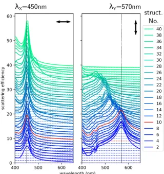
further-more consists of several blocks, while the longer wave-length yields one large structure, unifying all available blocks in a single element. This is a result of the con-strained size of the four constituents and is discussed in detail in reference.33 Finally, in figure 6 we show the spectra of all structures on the Pareto front. In-deed, the first structure (bottom of figure 6, number “1”, dark blue line) has a pronounced optical resonance at λ = 570 nm under Y polarization, while the scat-tering at the complementary objective (λ = 450 nm,
λX=450nm λY=570nm struct.
No.
Figure 6. Spectra of all structures on the Pareto front af-ter the multi-objective optimization with λX= 450 nm and
λY = 570 nm (see also figure5). The scattering efficiency is
shown for X polarized plane wave illumination on the left plot and for Y polarization on the right. The best com-promise structure is the number “10”, highlighted by red lines. Each successive spectrum is offset on the Y -scale by a positive step of 1. Hence, for example to get the actual scattering efficiency of structure “20”, 19 must be subtracted from the shown values.
X-polarization) is weak. The structure at the other end of the Pareto front yields the opposite image: a very strong resonance at λ = 450 nm occurs for X-polarization, while Y -polarized light is barely scattered (top, purple line in figure 6). In the “middle” of the Pareto-front, structures are found which yield reso-nances in both cases and can be considered a compro-mise between the two objective functions.
4. CONCLUSION
In conclusion, we demonstrated two different ap-proaches to multi-objective optimization of photonic nanostructures. The first approach is based on single-objective optimization algorithms, using a objective fitness function, which summarized multi-ple optimization objectives in a single number. This method can be used to design the line-shape of a spec-tral response over a larger wavelength range, which ef-fectively treats a problem of a large number of objec-tives (N considered wavelengths). However, such ap-proach becomes limited when several entirely different
quantities are used as optimization objectives, since the balancing of the different target values is crucial for the multi-objective fitness function. Hence, we pre-sented a second approach to multi-objective, namely Pareto optimization, which can be a promising alterna-tive in cases of very different target functions. Pareto optimization consists in the search of the set of non-dominated solutions to the problem. These solutions cannot be further optimized in all objective functions simultaneously. We demonstrated both approaches at the example of a multi-resonant silicon nanostructure, yielding comparable results.
In the future, EMO could be applied on many prob-lems in nano-optics, which would profit from efficient schemes to solve inverse problems. Examples go far beyond multiresonant antennas41 or polarization de-pendent tailored optical behavior.42,43 For instance nanoantennas for optimized nonlinear optical effects are particularly promising with respect to inverse design methods. For the maximization of optical second har-monic generation for instance,44,45 strong resonances could be concurrently designed at the fundamental and harmonic frequencies and furthermore tailored to yield strongest field-enhancements just at the surface of the nanoparticle.
ACKNOWLEDGMENTS
This work was supported by Programme Investisse-ments d’Avenir under the program ANR-11-IDEX-0002-02, reference ANR-10-LABX-0037-NEXT, by the LAAS-CNRS micro and nanotechnologies platform, a member of the French RENATECH network and by the computing facility center CALMIP of the University of Toulouse under grant P12167.
REFERENCES
[1] Novotny, L. and Hecht, B., [Principles of Nano-Optics ], Cambridge University Press, Cambridge ; New York (2006).
[2] Tan, S. J., Zhang, L., Zhu, D., Goh, X. M., Wang, Y. M., Kumar, K., Qiu, C.-W., and Yang, J. K. W., “Plasmonic Color Palettes for Photore-alistic Printing with Aluminum Nanostructures,” Nano Letters 14, 4023–4029 (July 2014).
[3] Duempelmann, L., Casari, D., Luu-Dinh, A., Gallinet, B., and Novotny, L., “Color Render-ing Plasmonic Aluminum Substrates with Angular Symmetry Breaking,” ACS Nano 9, 12383–12391 (Dec. 2015).
[4] Albella, P., Shibanuma, T., and Maier, S. A., “Switchable directional scattering of electromag-netic radiation with subwavelength asymmetric sil-icon dimers,” Scientific Reports 5, 18322 (Dec. 2015).
[5] Lindfors, K., Dregely, D., Lippitz, M., Engheta, N., Totzeck, M., and Giessen, H., “Imaging and Steering Unidirectional Emission from Nanoan-tenna Array Metasurfaces,” ACS Photonics 3, 286–292 (Feb. 2016).
[6] Wiecha, P. R., Black, L.-J., Wang, Y., Paillard, V., Girard, C., Muskens, O. L., and Arbouet, A., “Po-larization conversion in plasmonic nanoantennas for metasurfaces using structural asymmetry and mode hybridization,” Scientific Reports 7, 40906 (Jan. 2017).
[7] Baffou, G., Quidant, R., and Girard, C., “Heat generation in plasmonic nanostructures: Influ-ence of morphology,” Applied Physics Letters 94, 153109 (Apr. 2009).
[8] Kauranen, M. and Zayats, A. V., “Nonlinear plas-monics,” Nature Photonics 6, 737–748 (Nov. 2012). [9] Black, L.-J., Wiecha, P. R., Wang, Y., de Groot, C. H., Paillard, V., Girard, C., Muskens, O. L., and Arbouet, A., “Tailoring Second-Harmonic Gen-eration in Single L-Shaped Plasmonic Nanoan-tennas from the Capacitive to Conductive Cou-pling Regime,” ACS Photonics 2, 1592–1601 (Nov. 2015).
[10] Wiecha, P. R., Arbouet, A., Kallel, H., Peri-wal, P., Baron, T., and Paillard, V., “Enhanced nonlinear optical response from individual silicon nanowires,” Physical Review B 91, 121416 (Mar. 2015).
[11] Ginn, J. C., Brener, I., Peters, D. W., Wendt, J. R., Stevens, J. O., Hines, P. F., Basilio, L. I., Warne, L. K., Ihlefeld, J. F., Clem, P. G., and Sin-clair, M. B., “Realizing Optical Magnetism from Dielectric Metamaterials,” Physical Review Let-ters 108, 097402 (Feb. 2012).
[12] Albella, P., Poyli, M. A., Schmidt, M. K., Maier, S. A., Moreno, F., Sáenz, J. J., and Aizpurua, J., “Low-Loss Electric and Magnetic Field-Enhanced Spectroscopy with Subwavelength Silicon Dimers,” The Journal of Physical Chemistry C 117, 13573– 13584 (July 2013).
[13] Albella, P., Alcaraz de la Osa, R., Moreno, F., and Maier, S. A., “Electric and Magnetic Field Enhancement with Ultralow Heat Radiation Di-electric Nanoantennas: Considerations for Surface-Enhanced Spectroscopies,” ACS Photonics 1, 524– 529 (June 2014).
[14] Bakker, R. M., Permyakov, D., Yu, Y. F., Markovich, D., Paniagua-Domínguez, R., Gon-zaga, L., Samusev, A., Kivshar, Y., Luk’yanchuk, B., and Kuznetsov, A. I., “Magnetic and Elec-tric Hotspots with Silicon Nanodimers,” Nano Let-ters 15, 2137–2142 (Mar. 2015).
[15] Kuznetsov, A. I., Miroshnichenko, A. E., Brongersma, M. L., Kivshar, Y. S., and Luk’yanchuk, B., “Optically resonant dielectric nanostructures,” Science 354 (Nov. 2016). [16] Cao, L., Fan, P., Barnard, E. S., Brown, A. M.,
and Brongersma, M. L., “Tuning the Color of Sili-con Nanostructures,” Nano Letters 10, 2649–2654 (July 2010).
[17] Zhao, W., Liu, B., Jiang, H., Song, J., Pei, Y., and Jiang, Y., “Full-color hologram using spatial multiplexing of dielectric metasurface,” Optics Let-ters 41, 147 (Jan. 2016).
[18] Sivanandam, S. and Deepa, S., [Introduction to Genetic Algorithms ], Springer, Heidelberg (2008). [19] Forestiere, C., Donelli, M., Walsh, G. F., Zeni, E., Miano, G., and Dal Negro, L., “Particle-swarm optimization of broadband nanoplasmonic arrays,” Optics Letters 35, 133 (Jan. 2010).
[20] Feichtner, T., Selig, O., Kiunke, M., and Hecht, B., “Evolutionary Optimization of Optical Antennas,” Physical Review Letters 109, 127701 (Sept. 2012). [21] Forestiere, C., Pasquale, A. J., Capretti, A., Mi-ano, G., Tamburrino, A., Lee, S. Y., Reinhard, B. M., and Dal Negro, L., “Genetically Engineered Plasmonic Nanoarrays,” Nano Letters 12, 2037– 2044 (Apr. 2012).
[22] Forestiere, C., He, Y., Wang, R., Kirby, R. M., and Dal Negro, L., “Inverse Design of Metal Nanopar-ticles’ Morphology,” ACS Photonics 3, 68–78 (Jan. 2016).
[23] Ginzburg, P., Berkovitch, N., Nevet, A., Shor, I., and Orenstein, M., “Resonances On-Demand for Plasmonic Nano-Particles,” Nano Letters 11, 2329–2333 (June 2011).
[24] Tassadit, A., Macías, D., Sánchez-Gil, J. A., Adam, P. M., and Rodriguez-Oliveros, R., “Metal nanostars: Stochastic optimization of reso-nant scattering properties,” Superlattices and Mi-crostructures 49, 288–293 (Mar. 2011).
[25] Macías, D., Adam, P.-M., Ruíz-Cortés, V., Rodríguez-Oliveros, R., and Sánchez-Gil, J. A., “Heuristic optimization for the design of plasmonic nanowires with specific resonant and scattering properties,” Optics Express 20, 13146 (June 2012).
[26] Andkjær, J., Johansen, V. E., Friis, K. S., and Sig-mund, O., “Inverse design of nanostructured sur-faces for color effects,” JOSA B 31, 164–174 (Jan. 2014).
[27] Bigourdan, F., Marquier, F., Hugonin, J.-P., and Greffet, J.-J., “Design of highly efficient metallo-dielectric patch antennas for single-photon emis-sion,” Optics Express 22, 2337 (Feb. 2014). [28] Wiecha, P. R., Arbouet, A., Cuche, A., Paillard,
V., and Girard, C., “Decay rate of magnetic dipoles near nonmagnetic nanostructures,” Physical Re-view B 97, 085411 (Feb. 2018).
[29] Jensen, J. and Sigmund, O., “Topology optimiza-tion for nano-photonics,” Laser & Photonics Re-views 5, 308–321 (Mar. 2011).
[30] Girard, C., Wiecha, P. R., Cuche, A., and Du-jardin, E., “Designing Thermoplasmonic Proper-ties of Metallic Metasurfaces,” arXiv:1804.01111 [cond-mat, physics:physics] (Apr. 2018).
[31] Lu, J. and Vučković, J., “Nanophotonic compu-tational design,” Optics Express 21, 13351–13367 (June 2013).
[32] Piggott, A. Y., Lu, J., Lagoudakis, K. G., Petykiewicz, J., Babinec, T. M., and Vučković, J., “Inverse design and demonstration of a compact and broadband on-chip wavelength demultiplexer,” Nature Photonics 9, 374–377 (June 2015).
[33] Wiecha, P. R., Arbouet, A., Girard, C., Lecestre, A., Larrieu, G., and Paillard, V., “Evolutionary multi-objective optimization of colour pixels based on dielectric nanoantennas,” Nature Nanotechnol-ogy 12, 163–169 (Feb. 2017).
[34] Feichtner, T., Selig, O., and Hecht, B., “Plas-monic nanoantenna design and fabrication based on evolutionary optimization,” Optics Express 25, 10828–10842 (May 2017).
[35] Deb, K., [Multi-Objective Optimization Using Evo-lutionary Algorithms ], vol. 16, Wiley (2001). [36] Hu, J., Ren, X., Reed, A. N., Reese, T., Rhee,
D., Howe, B., Lauhon, L. J., Urbas, A. M., and Odom, T. W., “Evolutionary Design and Prototyp-ing of SPrototyp-ingle Crystalline Titanium Nitride Lattice Optics,” ACS Photonics 4, 606–612 (Mar. 2017). [37] Jung, J., “Robust Design of Plasmonic Waveguide
Using Gradient Index and Multiobjective Opti-mization,” IEEE Photonics Technology Letters 28, 756–758 (Apr. 2016).
[38] Girard, C., “Near fields in nanostructures,” Reports on Progress in Physics 68, 1883–1933 (Aug. 2005).
[39] Martin, O. J. F., Girard, C., and Dereux, A., “Generalized Field Propagator for Electromagnetic Scattering and Light Confinement,” Physical Re-view Letters 74, 526–529 (Jan. 1995).
[40] Wiecha, P. R., “pyGDM – A python toolkit for full-field electro-dynamical simulations and evolutionary optimization of nanostructures,” arXiv:1802.04071 [cond-mat, physics:physics] (Feb. 2018).
[41] Aouani, H., Šípová, H., Rahmani, M., Navarro-Cia, M., Hegnerová, K., Homola, J., Hong, M., and Maier, S. A., “Ultrasensitive Broadband Probing of Molecular Vibrational Modes with Multifrequency Optical Antennas,” ACS Nano 7, 669–675 (Jan. 2013).
[42] Gao, Z. and Wang, Z.-Y., “Terahertz Plasmonic Cross Resonant Antenna,” Journal of Electromag-netic Waves and Applications 25, 1730–1739 (Jan. 2011).
[43] Dopf, K., Moosmann, C., Kettlitz, S. W., Schwab, P. M., Ilin, K., Siegel, M., Lemmer, U., and Eisler, H.-J., “Coupled T-Shaped Optical Anten-nas with Two Resonances Localized in a Common Nanogap,” ACS Photonics 2, 1644–1651 (Nov. 2015).
[44] Harutyunyan, H., Volpe, G., Quidant, R., and Novotny, L., “Enhancing the Nonlinear Optical Re-sponse Using Multifrequency Gold-Nanowire An-tennas,” Physical Review Letters 108, 217403 (May 2012).
[45] Celebrano, M., Wu, X., Baselli, M., Großmann, S., Biagioni, P., Locatelli, A., De Angelis, C., Cerullo, G., Osellame, R., Hecht, B., Duò, L., Ciccacci, F., and Finazzi, M., “Mode matching in multireso-nant plasmonic nanoantennas for enhanced second harmonic generation,” Nature Nanotechnology 10, 412–417 (May 2015).