HAL Id: cea-01840770
https://hal-cea.archives-ouvertes.fr/cea-01840770
Submitted on 16 Jul 2018HAL is a multi-disciplinary open access archive for the deposit and dissemination of sci-entific research documents, whether they are
pub-L’archive ouverte pluridisciplinaire HAL, est destinée au dépôt et à la diffusion de documents scientifiques de niveau recherche, publiés ou non,
Multichannel OSL dosimetry for dose verification in
radiotherapy
Sylvain Magne, Loïc de Carlan, Soizic Sorel, Aurélie Isambert, André Bridier,
Pierre Ferdinand, Jean Barthe
To cite this version:
Sylvain Magne, Loïc de Carlan, Soizic Sorel, Aurélie Isambert, André Bridier, et al.. Multichannel OSL dosimetry for dose verification in radiotherapy. 12th International Congress of the International Radiation Protection Association (IRPA), International Society of Radiology, Oct 2008, Buenos Aires, Argentina. �cea-01840770�
Buenos Aires (Argentina), 19-24 October 2008, paper FP0440
Multichannel OSL dosimetry for dose verification in radiotherapy
Sylvain Magnea*, Loïc de Carlanb, Soizic Sorelb, Aurélie Isambertc, André Bridierc, Pierre Ferdinanda, Jean Barthed
a
CEA, LIST, Laboratoire de Mesures Optiques, F-91191 Gif-sur-Yvette cedex, France.
b
CEA, LIST, Laboratoire National Henri Becquerel, F-91191 Gif-sur-Yvette, France.
c
Institut Gustave Roussy, Service de Physique, 39 rue Camille Desmoulins, F-94805 Villejuif, France.
d
CEA, LIST, Département des Technologies du Capteur et du Signal, F-91191 Gif-sur-Yvette, France.
Abstract. An innovative multichannel fibre-coupled Optically Stimulated Luminescence (OSL) dosimeter is
proposed for on-line in vivo quality assurance in Radiation Therapy (RT). Small Al2O3:C fibre crystals (TLD500)
are used as OSL detectors, incorporated into a rugged, radiation-resistant and radiation-transparent OSL fibre sensor design. The temperature and fading dependences of OSL fibre sensors and stability vs cumulated dose have been tested with a X-ray generator. Predosed OSL sensors tested at Institut Gustave Roussy (IGR) show a good repeatability in multichannel operation. Sensor calibration and depth-dose measurements with electron beams have been performed with a Saturne 43 LINAC in reference conditions at CEA-LNHB (ionizing radiation reference laboratory in France). The difference between absorbed doses measured by OSL and an ionization chamber was within ± 0.9 % (for a dose of about 1 Gy) despite a sublinear dose response. Finally, a single calibration curve was used for all beams as energy independence vs electron energy was found in the range [9 MeV, 18 MeV]. Angular independence was found as well in the range [0°, 45°] when the OSL sensor is equipped with its bolus.
KEYWORDS: Optically Stimulated Luminescence (OSL), Fibre optics, in vivo dosimetry, Radiation Therapy.
1. Introduction
Principles of OSL are now well known [1]. It is closely related to thermoluminescence (TL) except that electrons stored within the material are released by light (laser) instead of by heat. OSL dosimetry is investigated at CEA LIST (Saclay, France) since 1994. Two generations of OSL systems have been developed in the purpose of a remote OSL dosimetry via an optical fibre link [2].
The first generation system (OSL I) relied on Alkaline-Earth Sulphide (AES) materials, stimulated by infrared laser light. The OSL is in the red part of the visible spectrum. The corresponding absorption in silica fibres is ~10 dB/km enabling remote operation up to several hundreds of meters. The OSL I system did not provide tissue-equivalent dose measurement and its dose range was [1 mGy, 10 Gy]. It was well suited to dismantling applications because of its unique feature of remote dose monitoring inside narrow pipes and tanks and was widely used at CEA and AREVA NC (Marcoule, France). The second generation system (OSL II) relies on alumina crystals, stimulated by a green laser light. The OSL is in the blue part of the visible spectrum. The corresponding absorption in silica fibres is ~80 dB/km and the practical fibre length is thus restricted to several tens of meters. The OSL II system was investigated for radiation protection applications that require a limit in dose detection better than some µGy and may involve a compensation technique to fit the tissue response.
The work described in this paper is done within the European Project MAESTRO, dedicated to the development of technologies and cancer treatment techniques in Radiation Therapy (RT). The MAESTRO Project is managed by the CEA LIST and involves several cancer research institutes and hospitals among which the Institut Gustave Roussy (IGR), as centre of expertise.
*
Worldwide, the estimated number of new cancer cases each year is expected to rise from 10 millions in 2000 to 15 millions by 2020. Within the European Union, it is over 1.5 million new cancer cases that are diagnosed every year. Therefore, combating cancer is a major societal and economical issue for developed countries. About 60 % of all cancer patients are treated totally or partially by RT. Most RT treatments involve photon and electron beams delivered by linear accelerators (LINACs). The so-called conformal RT and Intensity-Modulated RT (IMRT) improve the conformity of the dose distribution to the tumour leading to a reduced dose to surrounding healthy tissues and critical organs. In return, it brings additional complexity and processing time in the dosimetry because of high-dose gradients and more complex ballistics.
Treatment Planning Systems (TPS) are used to plan the treatment. Accidents in Radiation therapy have been associated with the incorrect use of TPS or false dose measurement during its commissioning. In vivo dosimetry will become a legal requirement in France in order to provide a true check of the absorbed dose actually delivered. The use of in vivo dosimetry will be mandatory by 2011 in order to deliver radiation therapy treatments. According to the Code of Practice (CoP) IAEA TRS-398 [3], the difference between planned and delivered doses must remain within typically 2 to 3 %. If the difference exceeds 5 %, the reasons for discrepancy must be investigated and the patient treatment not initiated.
In vivo dosimetry is traditionally provided by ThermoLuminescent Dosimeters (TLDs), Metal-Oxide Semiconductor Field-Effect Transistor (MOSFETs) or PN-junction-type diodes. However, in vivo OSL dosimetry with Al2O3:C crystals is recently gaining acceptance from the medical community
[4-7]. As a matter of fact, dosimetric-grade alumina crystals (grown in reducing atmosphere in the presence of carbon) is one of the leading dosimetric material owing to its high sensitivity. Recent clinical investigations were conducted with InLightTM Dot dosimeters (associated to the microStar reader) or LuxelTM film dosimeters, collected after irradiation and sent to Landauer Inc. (Glenwood, IL) for readout. A readout does not bleach the film (i.e. only removes a small part of the data) that can be stored and read at a later date. However, in clinical conditions, medical physicists want to save time in collection procedure and get absorbed dose data immediately available after treatment in order to provide suitable action in case of abnormal dose delivery. The real-time monitoring of the cumulated doses may be also mandatory for specific treatments (e.g. Total Body Irradiation) and may be obtained from real-time OSL or radioluminescence (RL) of Al2O3:C crystals.
Therefore, the OSL II system of the CEA LIST has been upgraded into a multichannel version in the purpose of performing on line in vivo dose verification during Radiation Therapy treatments.
2. Description of the OSL system 2.1 OSL fibre sensors
Figure 1: OSL sensors for RT (CEA LIST) An OSL fibre sensor consists of an optical fibre cable
with a SMA connector at one end and a moulded cylindrical epoxy head (Ø = 6 mm) at the other (Fig. 1), rigidly fixed onto the cable extremity that protects the crystal (Ø = 1 mm, 1 mm long) affixed near the end of a silica fibre (Ø = 0.6 mm) and provides a stable coupling of light. TLD500 alumina fibre crystals
purchased from Ural State Technical University (Ekaterinburg, Russia) were used. The sensors exhibit circular symmetry along the fibre/crystal axis.
Al2O3:C OSL fibre sensors are radiation-transparent (made with polymers) and do not involve any
metallic part. They are compatible with in vivo applications (small [mm size]), non-toxic, chemically inert and sterilizable), electromagnetic-immune, and exhibit low energy and angular dependences.
Buenos Aires (Argentina), 19-24 October 2008, paper FP0440
2.2 Multichannel OSL reader
Several research groups have investigated fibre sensing solutions for on-line remote dose measurement in RT, mostly with Al2O3:C crystals [1, 8-11]. The main innovation described in this paper lies in the
multisensor capability of our OSL fibre reader in a purpose of cost-effectiveness (improvement of the cost/sensor figure) [10] and easier data acquisition and archiving. Furthermore, the RL signal may be also measured during irradiation from one or multiple sensors (time-sampling by the optical switch). The OSL/RL sensor, linked to a fibre cable, thus provides a real-time estimation of the dose rate (or cumulated dose) during treatment and on-line estimation of the dose after treatment. The objective is to provide an accurate, cost-effective, efficient and reliable in vivo dosimetry to fulfil the quality assurance in RT while keeping operational costs at a reasonable level.
Figure 2: Multichannel OSL reader (CEA LIST) Finally, in the context of an ever-increasing
complexity of the radiation treatments, the purpose is also to save time in calibration and maintenance, taking advantage of both radiation hardness and material stability of the OSL sensor relaxing the need for frequent recalibrations. The OSL reader is built in a 19-inch enclosure (6U) that includes a 16-channel optical fibre switch actuated by a stepper motor, an optical case and power/USB electronics [10] (Fig. 2).
The multichannel OSL reader is linked to a laptop by an USB connection and handled through dedicated software written in LabView. Its basic scheme is based upon previous work [12] (Fig. 3). Figure 3: Basic scheme of the multichannel OSL reader of the CEA LIST
Since the decay time of the RL signal is much longer than the LINAC pulses (~ 32 ms compared to some µs), a gating circuit may be inserted between the Amplifier-Discriminator and the Counter (Fig. 3) in order to remove Cerenkov pulses from fibres (“stem effect”) by time discrimination. Fortunately, the amount of Cerenkov light is small compared to RL (~ 5 %) and so the “dual fibre method” is also often used. It consists in having two fibers inside the same cable. One fibre is mounted onto the sensor head and collects the RL (and Cerenkov light) while the other is left unconnected and only collects the Cerenkov light. The signal from the sensor fibre is then subtracted to that of the unconnected one. After irradiation, each OSL sensor is remotely stimulated using a CW-Diode-Pumped Solid-State (DPSS) laser (@ 532 nm, 200 mW) and bleached for a next use. The reader works in the Continuous-Wave (CW) mode (i.e. CW-OSL). The OSL stimulation is triggered by an electromagnetic shutter once the switch has moved from its reference position to the selected output. The OSL (@ 410 nm) is then collected by the optical fibre, separated by a dichroïc beamsplitter, filtered and eventually detected by a photomultiplier (PM) in photon-counting mode.
The counting error due to counter dead time (20 ns) is about 0.2 % at 2 Gy. Prior to any calculations, the recorded counting rate is corrected for dead time influence. Then, the background signal is averaged from the latest portion of the OSL signal and subtracted from the raw signal. The background is due to dark counts in the PM tube, imperfect filtering of the laser light and also fluorescence of the OSL crystal (metal impurities (Cr3+) and deep-trap charges). The corrected signal is then integrated and multiplied by a calibration coefficient to provide the absorbed dose. The error in OSL measurement is due to counting statistics (1/√N), background and temperature corrections. The integration usually runs until the OSL signal gets well below 0.1 % of the integral.
The bleaching time Tb depends mainly on laser wavelength and power (the higher the laser power, the
lower Tb). To a lesser extent, it also depends on dose (the higher the dose, the higher Tb). The
integration time Ti is chosen identical to Tb in order to improve the reproducibility of OSL data
(integration of the whole OSL decay curve). The time Tbg for background correction usually lasts
some seconds. The OSL readout time (Tr = Tb + Tbg) is ~ 20 s for a stimulation intensity of ~ 25
mW/mm2. The total readout time is 4 minutes for 12 sensors, yet compatible with the treatment protocol. The limit in dose detection is ~ 1 mGy.
The OSL response (Gy/cts) also depends on light transmission along the measurement chain from sensor to PM. Anomalies in light transmission or device operation are unlikely to occur with our OSL system but nevertheless have to be taken seriously in a medical application. Consequently, a self-checkup of every critical device (laser, PM, optical switch) is done before use. Two photodiodes are inserted into the case. A reference photodiode monitors laser power and provides both check of laser status and reference for calibrating the measurement chain. A fluorophore is placed inside the unit, located nearby a temperature sensor (Pt100), and connected to one output of the optical switch (15
outputs are left free for use). The calibration of the measurement chain is obtained by dividing the photomultiplier output (cts/s) by the voltage of the reference photodiode.
Finally, the OSL dosimeter is safe when used properly. However, eye safety is also a matter of concern in case of abnormal use. The return signal photodiode monitors the laser signal brought back by the fibre and checks the integrity of the optical connection in order to switch the laser beam off in case of disconnection.
3. Preliminary tests (X-ray generator)
Temperature, fading and stability tests have been performed in laboratory with a X-ray generator (80 kV) equipped with a dedicated lead cell rigidly fixed onto its mainframe. OSL sensors are inserted inside a steel cylinder (Ø = 2 cm) enabling tight and reproducible positioning under the photon flux. 3.1 Temperature dependence of OSL signal
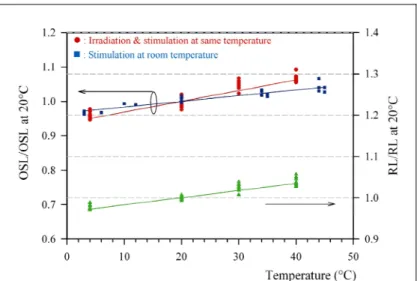
The temperature of a dosimeter is likely to change depending on its placement on the patient’s body. We investigated the temperature dependence of the RL and OSL measurements (Fig. 4). An OSL sensor was permanently fixed inside the cylinder and temperature-stabilized. Irradiations were performed in less than one minute so that the sensor temperature was kept constant (thanks to thermal inertia of the cylinder).
The temperature coefficient of the RL signal is ~ 0.18 %.K-1. The temperature coefficient of OSL depends on whether OSL stimulation is done immediately after irradiation (i.e. at same temperature) or at room temperature (@ 20°C) after sensor thermalization. In the first case, the temperature coefficient is 0.3 %.K-1 while it is 0.16 %.K-1 in the latter.
The effect of temperature cannot be neglected when performing on-line OSL dosimetry with TLD500
crystals. In practice, however, a reference temperature of 28 °C ± 2 °C is usually taken as surface temperature and the uncertainty in dose measurement due to temperature fluctuations is ~ ± 0.6 %.
Buenos Aires (Argentina), 19-24 October 2008, paper FP0440
Figure 4: Change in OSL and RL vs sensor temperature (normalized to mean values at 20°C)
3.2 Fading of OSL signal
The time delay between irradiation and OSL readout may change considerably according to the protocol of medical physicists. We conducted a fading test at 20 °C for a constant irradiation time of 20 sec (0.3 Gy). The time delay between the end of irradiation and onset of OSL readout was adjusted between 5 seconds and 2 hours. On Fig. 5, the OSL signal is plotted with respect to delay time and exhibits a small fading of about -1 % per decade (order of magnitude in time) [11] that
may be reduced by using a
reproducible readout protocol.
Figure 5: Fading of the OSL vs time delay between end of irradiation and onset of OSL readout.
Jursinic [5] observed a similar fading with InLightTM dosimeters
(Landauer Inc.) but also
observed a transient signal which decays away in a few minutes after irradiation and recommends waiting at least 8 minutes to get a more stable readout. We did not observe any transient behaviour with TLD500 alumina
crystals, indicating that stable OSL readouts may be obtained immediately after irradiation.
3.3 Expected sensor lifetime
A “survival test” was performed at CEA LIST LNHB with a GammaCell irradiator (60Co source, dose rate ~ 177 Gy/min). The dose fraction started at 500 Gy and was multiplied by a factor of 2 after each series of 4 (4 x 500 Gy, 4 x 1 kGy, 4 x 2 kGy, etc). After each dose fraction, the OSL sensor was removed from the irradiator and connected to the OSL reader for bleaching and OSL testing. After laser bleaching, a constant test dose (0.8 Gy) was delivered to the OSL sensor with the X-ray generator. Fig. 6 shows the evolution of the OSL signal for a constant test dose (delivered throughout the experiment) with respect to cumulated dose. We ran this experiment until a cumulated dose of 64 kGy was reached. The experiment was stopped because of lack of availability of the irradiator. The OSL sensor survived the test and is likely to withstand a higher dose.
Figure 6: OSL response vs cumulated dose (“survival test”) This experiment shows that the
lifetime of an OSL sensor
exceeds 3 years under
continuous use (assuming an average annual dose rate of ~ 20 kGy/year). Furthermore, its
response is stable with
cumulated dose (within ± 2 %), thus relaxing the need for frequent recalibrations.
4. Repeatability of the OSL response vs dose
The repeatability of OSL sensor response has been investigated at IGR using a Varian Clinac 2300 LINAC (6 MV photon beam, field size (FS): 10 x 10 cm2, Source-Surface Distance (SSD) = 1 m), see Fig. 7. The OSL reader is located in a control room (next to the irradiation room) and fibre cables run through the wall (length: 28 m). The repeatability of OSL data depends both on the stability of the OSL sensor vs dose and stability of the optical measurement chain (mainly the optical switch).
Figure 7: Placement of the OSL sensor under the LINAC beam (Varian Clinac 2300) [courtesy IGR]
*
4.1 Stability of the OSL sensor’s response vs dose
We observed that both OSL and RL responses were changing with respect to cumulated dose ([0 - 100 Gy]) in the early use of the sensor. The RL decreased with cumulated dose whereas the OSL increased in a significant proportion (~ 30 %). This unstable behaviour is not due to change in light coupling as it would affect both signals in a similar way. It is due to the cumulative filling of deep traps that are not emptied by optical stimulation [13-14]. The sensor response eventually reaches a steady-state value vs cumulated dose once deep traps are filled. We have thus pre-irradiated four similar OSL sensors under increasing radiation predoses (60Co source) in order to check for a possible correlation between repeatability and predose: #4: 250 Gy, #3: 500 Gy, #2: 750 Gy and #1: 1 kGy.
4.2 Repeatability in multichannel operation
A repeatability test at constant dose fraction (1.2 Gy) was realized with the four predosed sensors fixed on a polystyrene (PS) block and inserted into a groove filled with wax (see inset Fig. 8). The sensors were covered by a 2 cm-thick PS slab (at dmax). Fig. 8 shows the repeatability of the OSL (between 0.6
% and 1.3 %) vs cumulated dose that demonstrates the stability of both predosed sensors and optical switch.
This result shows that the minimum predose required is less than 250 Gy. It is done once and for all, and would be included in the manufacturing process, prior to sensor calibration.
Buenos Aires (Argentina), 19-24 October 2008, paper FP0440
5. Evaluation of OSL fibre sensor with electron beams 5.1 Irradiation protocol
Figure 9: OSL sensor with PMMA bolus The treatment protocols with electron and photon beams
are different, due to different interactions involved with matter. Since the sensors are placed onto the patient’s skin, the protocol with electron beams involves a PMMA (plexiglass) bolus (see Fig. 9). The bolus shifts the depth of maximum dose onto the skin to minimize placement-induced errors (small dose gradient). Its thickness depends on electron energy (21 mm for 12 MeV).
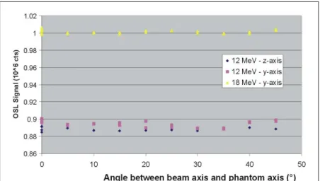
5.2 Angular (in)dependence
Figure 10: Placement of the OSL sensor onto the phantom surface and rotation along z-axis The sensor orientation is likely to change with
respect to irradiation beam depending on the sensor placement along the patient’s body. We have investigated the angular response of the OSL sensor equipped with its bolus and placed onto the surface of a water phantom (30 x 30 cm2, depth = 15 cm). Let x be the beam axis and z the axis parallel to gravity, the phantom was rotated with respect to beam axis within the (x-y) plane [z-axis] (Fig. 10). The OSL sensor was placed along z-axis and along y-axis. The irradiation conditions were kept constant and done with a Saturne 43 LINAC of the CEA LIST LNHB (Laboratoire National Henri Becquerel), primary dosimetry standard laboratory in France.
We did not observe any change in dose measurement as the phantom was moved between [0, 45°] for both planes (x-y) and (x-z) (Fig. 11). This independence was checked for 12 MeV and 18 MeV. Figure 11: Angular independence of the OSL sensor equipped with its bolus
x z y x z y
5.3 Calibration and energy (in)dependence
Calibrations and Depth-Dose (DD) measurements were made with a Saturne 43 LINAC, according to CoP TRS-398 [3] that involves a water cube phantom (side length: 30 cm, wall thickness: 4 mm), FS= 10 x 10 cm2 and SSD = 1 m. The dose rate was 200 MU/min (2 Gy/min) at reference depth (zref).
Three reference energies were used (9, 12 and 18 MeV).
A single OSL sensor (#3) was used for the experiment and connected to output #1 of the optical switch. The head of the OSL sensor was inserted and fixed into a PMMA tube (Ø = 13 mm) and immersed inside water. This sensor arrangement was placed vertically (transverse to the beam) and located on the horizontal central beam axis.
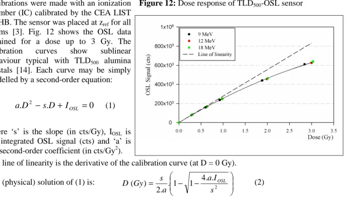
Figure 12: Dose response of TLD500-OSL sensor
Calibrations were made with an ionization chamber (IC) calibrated by the CEA LIST LNHB. The sensor was placed at zref for all
beams [3]. Fig. 12 shows the OSL data obtained for a dose up to 3 Gy. The calibration curves show sublinear behaviour typical with TLD500 alumina
crystals [14]. Each curve may be simply modelled by a second-order equation:
0 .
.D2 −sD+ IOSL =
a (1)
where ‘s’ is the slope (in cts/Gy), IOSL is
the integrated OSL signal (cts) and ‘a’ is the second-order coefficient (in cts/Gy2).
The line of linearity is the derivative of the calibration curve (at D = 0 Gy).
The (physical) solution of (1) is:
− − = . 1 1 4. .2 . 2 ) ( s I a a s Gy D OSL (2)
The observed change in slope vs electron energy is very small (± 0.25 %) and the second-order coefficients do not depend on electron energy within the experimental uncertainties. Indeed, at zref, the
average electron energies impinging onto the Al2O3 crystal are about 6.5, 5.3 and 4.3 MeV for 18, 12
and 9 MeV respectively. By virtue of the smallness of the Al2O3 crystal (mm) with respect to particle
ranges (cm), the dose is mostly deposited by electrons coming from crystal surroundings (polymers, water) according to Bragg-Gray principle. The dose correction factor DAl2O3/Dwater involves relative
mass collision stopping power of Al2O3 to that of water (ESTAR database,
www.physics.nist.gov/PhysRefData/). A rough estimate shows that its energy dependence is indeed very small (± 0.2 % in the same energy range). To illustrate this, only one –energy independent- fit curve is used in the fit of the OSL response in Fig. 12 (s = 278.103 cts/Gy and a = 22.5.103 Cts/Gy2). 5.4 Depth-dose measurements
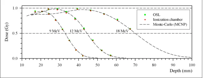
The sensor arrangement was moved inside the water, along the central beam axis, at different depths according to electron energy. Integrals of OSL signals were then converted in absorbed doses using equation (2) and compared with reference dose data (IC). Fig. 13 shows the fairly good agreement (± 0.9 %) between measured and reference depth-dose data for the three reference energies.
The OSL sensor, PMMA tube and water phantom have been modelled with the MCNP5 code (Monte-Carlo N-Particles, Los Alamos National Laboratory, USA). Since the detection volume (mm3) is small with respect to accelerator and cube phantom, the computation time may take hours or days depending on accuracy. In order to save calculation time, the LINAC beam was modelled by three simplified
Buenos Aires (Argentina), 19-24 October 2008, paper FP0440
Figure 13: Depth-dose curves and comparison to MCNP modellings for each nominal energy of the LINAC beam (field size: 10 x 10 cm2, Gaussian distribution: a) E = 8 MeV, FWHM = 2.16 MeV; b) E = 10.4 MeV, FWHM = 2.66 MeV; c) E = 16 MeV, FWHM = 5.5 MeV)
6. Conclusion
In the context of an increasing demand for quality assurance of the dose in RT, Al2O3:C-based OSL
film dosimetry is gaining wide acceptance among medical physicists in the purpose of performing in vivo dose measurements. However, on-line in vivo dosimetry is requested for by the medical community in order to provide a quick assessment of delivered doses and to take suitable action in clinical conditions. Al2O3-OSL fibre sensors are potentially attractive for this purpose.
In the purpose of cost-effectiveness and easier data handling, the CEA LIST has designed an innovative multichannel OSL fibre reader. TLD500 alumina fibre crystals were used as OSL detectors.
The sensing head of the OSL sensor is rigidly fixed onto the fibre cable and shows a high mechanical stability. It is in vivo compatible, radiation-transparent and radiation-resistant (dose > 60 kGy).
The fading of OSL signal is small (~ -1 % per decade) and no transient effect is observed, enabling prompt OSL readouts after irradiation. A reproducible readout procedure would reduce fading-induced uncertainty. OSL also depends on both irradiation and stimulation temperatures. The sensitivity is minimum (0.16 %.K-1) when OSL stimulation is done at constant temperature. The repeatability of the OSL dosimeter mainly depends on stability of both predosed OSL sensors and measurement chain (mainly the optical switch). It was evaluated in pre-clinical conditions at IGR under multichannel operation (4 sensors) with photon beams. It is satisfactory (between 0.6 % and 1.3 %) and not affected by repeated connections & disconnections. The repeatability was also evaluated using high-energy electron beams in reference conditions. Sensor calibration and depth-dose measurements were performed with a Saturne 43 LINAC at CEA LIST LNHB. Calibration curves show a sublinear behaviour accurately fitted by an energy-independent second-order equation (in the range [9 MeV-18 MeV]) since the energy dependence is very small (± 0.25 %) in this energy range. The difference between absorbed doses measured by OSL and the IC is ± 0.9 % for 1 Gy. Finally, the OSL fibre sensor equipped with its bolus is insensitive to angular variations in the range [0°, 45°].
All these results confirm that Al2O3:C OSL fibre sensors and multichannel reader approach have great
potential for achieving in vivo on-line dosimetry in RT. Further tests in pre-clinical conditions at IGR facilities, checking the compliance of the system and software with respect to medical specifications, will be reported.
Besides Radiation therapy, this instrumentation may also be used in many other applications such as radiology in medicine, nuclear industry (dismantling of nuclear installations, monitoring of nuclear waste repository sites and installations, nuclear reactor monitoring {power plants and submarines}), or process controls (food irradiation, composite material curing, density analysis, etc).
Acknowledgements
This work is done in the framework of both French CODOFER Project (Agence Nationale de la Recherche - Technologie pour la Santé (TECSAN)) and European Integrated Project CE503564 MAESTRO (Methods and Advanced Equipments for the Simulation and Treatment in Radio Oncology, www.maestro-research.org) of the 6th Framework Program, granted by the European Commission.
Sylvain Magne would like to thank Dominique Chambellan for his assistance with the X-ray generator, Aimé Ostrowsky and Jean-Marc Bordy for their assistance with the Saturne 43 LINAC, Valérie Lourenco and Tristan Garcia for their assistance with the GammaCell, Olivier Gal, Amandine Fallet and Guillaume Bouhot for MCNP modellings.
REFERENCES
[1] AKSELROD, M.S., et al., Optically Stimulated Luminescence and its use in medical dosimetry, Radiat. Meas. 41 (2007) S78.
[2] MAGNE, S. and FERDINAND P., Fiber Optic remote γ Dosimeters based on Optically Stimulated Luminescence: State-of-the Art at CEA, IRPA 11 Conference, Madrid (2004).
[3] INTERNATIONAL ATOMIC ENERGY AGENCY, Absorbed dose determination in external
beam radiotherapy: An international Code of Practice for dosimetry based on standards of absorbed dose to water, Technical Reports Series No. 398, IAEA, Vienna (2000).
[4] SCHEMBRI, V., HEIJMEN, B.J.M., Optically stimulated Luminescence (OSL) of carbon-doped aluminum oxide (Al2O3:C) for film dosimetry in radiotherapy, Med. Phys. 34 (2007) 2113.
[5] JURSINIC, P.A., Characterization of optically stimulated luminescent dosimeters, OSLDs, for clinical dosimetric measurements, Med. Phys. 34 (2007) 4594.
[6] YUKIHARA, E.G., et al., Evaluation of Al2O3:C optically stimulated luminescence (OSL)
dosimeters for passive dosimetry of high-energy photon and electron beams in radiotherapy, Med. Phys., 35 (2008) 260.
[7] VIAMONTE, A., et al., Radiotherapy dosimetry using a commercial OSL system, Med. Phys. 35 (2008) 1261.
[8] AZNAR, M.C., et al., Real-time optical fibre luminescence dosimetry for radiotherapy: physical characteristics and applications in photon beams, Phys. Med. Biol., 49 (2004) 1655.
[9] MARCKMANN, C.J., et al., Optical fibre dosemeter systems for clinical applications based on radioluminescence and optically stimulated luminescence from Al2O3:C, Radiat. Prot. Dosim., 120
(2006) 28.
[10] MAGNE, S., et al., Multichannel fibre optic dosimeter based on OSL for dose verification during radiotherapy treatments, EWOFS (Proc. of the SPIE 6619, 3rd European Workshop on Optical Fibre Sensors Napoli (Italy)), 4-6 July 2007, Society of Photo-Optical Instrumentation Engineers, 1N1.
[11] MAGNE, S. et al., Multichannel dosemeter and Al2O3:C Optically Stimulated Luminescence
Fibre sensors for use in radiation therapy – evaluation with electron beams, Radiat. Prot. Dosim. (in press).
[12] RANCHOUX, G., et al., Fibre remote Optoelectronic gamma dosimetry based on Optically Stimulated Luminescence of Al2O3:C, Radiat. Prot. Dosim., 100 (2002) 255.
[13] EDMUNDS, J.M. et al., CW-OSL measurement protocols using optical fibre Al2O3:C
dosemeters, Radiat. Prot. Dosim. 119 (2006), 368.
[14] YUKIHARA, E.G., et al., Effect of high-dose irradiation on the optically stimulated luminescence of Al2O3:C, Radiat. Meas. 38 (2004) 317.


![Figure 7: Placement of the OSL sensor under the LINAC beam (Varian Clinac 2300) [courtesy IGR]](https://thumb-eu.123doks.com/thumbv2/123doknet/13471259.412560/7.892.543.793.297.801/figure-placement-osl-sensor-linac-varian-clinac-courtesy.webp)