HAL Id: hal-01629906
https://hal.archives-ouvertes.fr/hal-01629906
Submitted on 6 Nov 2017HAL is a multi-disciplinary open access archive for the deposit and dissemination of sci-entific research documents, whether they are pub-lished or not. The documents may come from teaching and research institutions in France or abroad, or from public or private research centers.
L’archive ouverte pluridisciplinaire HAL, est destinée au dépôt et à la diffusion de documents scientifiques de niveau recherche, publiés ou non, émanant des établissements d’enseignement et de recherche français ou étrangers, des laboratoires publics ou privés.
Synthesis and characterization of monolithic CVD-SiC
tubes
Patxi Drieux, Georges Chollon, Sylvain Jacques, Guillaume Couégnat,
Stéphane Jouannigot, Patrick Weisbecker
To cite this version:
Patxi Drieux, Georges Chollon, Sylvain Jacques, Guillaume Couégnat, Stéphane Jouannigot, et al.. Synthesis and characterization of monolithic CVD-SiC tubes. Journal of the European Ceramic Soci-ety, Elsevier, 2016, 36 (8), pp.1873 - 1883. �10.1016/j.jeurceramsoc.2016.02.024�. �hal-01629906�
Synthesis and Characterization of Monolithic CVD-SiC
Tubes
Patxi Drieux, Georges Chollon*, Sylvain Jacques, Guillaume Couégnat, Stéphane Jouannigot, Patrick Weisbecker†
Laboratoire des Composites Thermostructuraux (CNRS-CEA-SAFRAN), University of Bordeaux, 3, allée de La Boétie, 33600 Pessac, France
* Correspondance: Tel. +33 5 56 84 47 27, e-mail : [email protected] †
The authors dedicate this article to the memory of our colleague P. Weisbecker who has recently passed away
Abstract
The high open porosity of SiC/SiC composites is problematic for uses in advanced thermal or confinement systems. A strong and gas-tight SiC sheath would helpfully complete the composite structure. The aim of this work was to prepare and characterize long, free standing and high strength SiC tubes prepared through a rapid near net shape manufacturing process. The tubes were produced by continuous chemical vapor deposition (CVD) at atmospheric pressure using CH3SiHCl2/C3H6/H2 mixtures. The composition, morphology and microstructure of the CVD-SiC tubes were analyzed in details. The Si/C ratio and crystalline state through wall thickness are related to the progress of gas phase reactions during continuous deposition. The silicon excess in the CVD-SiC coating can be reduced by preheating gases and adding C3H6. C-ring specimens cut from the obtained tubes were submitted to compressive tests at room and high temperature to assess the failure properties and thermomechanical behavior.
Key words: Chemical Vapor Deposition, Silicon Carbide, Ceramic Tubes,
Microstructure, Mechanical properties
1. Introduction
Silicon carbide (SiC) combines high specific strength, stiffness, thermal shock and oxidation resistance, but it is too brittle to be used as a structural material in the bulk form. This drawback is suppressed in SiC/SiC composites, one of the most advanced forms of SiC-based materials. These materials result from the development of the last generation of small diameter fibers, chemical vapor infiltrated (CVI) matrix and interphase, the interlayer material responsible for the non-brittle behavior of these composites [1-2].
Besides high thermomechanical properties, pure crystalline SiC materials combine high thermal conductivity and corrosion resistance making SiC/SiC composites particularly suitable for heat exchangers in advanced thermal systems [3]. The low neutron activation properties of high purity SiC [4] further suggested to use near stoichiometric SiC/SiC composites for first wall and blanket in future fusion energy systems [5-6], or for nuclear fuel claddings in Generation IV gas-cooled fast fission reactors (GFR) [7-8].
It leads to unacceptable values of permeability with respect to the low tolerable level of gas leakage allowed for such nuclear purposes. It thus implies the juxtaposition of at least one additional sealing layer to the SiC/SiC composite structure to ensure imperviousness, e.g. by using a continuous and dense CVD-SiC sheath of high specific mechanical properties [7].
The synthesis of a high strength and a few hundreds of microns thick CVD-SiC layer requires a process compatible with a very low amount of surface flaws and a high deposition rate. A cold wall CVD reactor operating at atmospheric pressure is more relevant than classical isothermal and low pressure CVI in this case. Commercial CVD-SiC monofilaments so obtained have indeed a remarkably high strength [9], while the deposition rate is more than three orders of magnitude higher than for CVI [10].
On the basis of the CVD-SiC filament processing experience, CVD-SiC tubes were prepared by atmospheric pressure CVD (APCVD) using dichloromethylsilane (DCMS, CH3SiHCl2) diluted in hydrogen as the SiC precursor [11]. CVD-SiC tubes could be obtained in both static and continuous configuration. This APCVD process was thoroughly investigated through both gas and solid analyses using the former option, while the synthesis of a few decimeters long specimens was demonstrated in the latter configuration [11]. As a follow-up, the objective of the present study is to characterize in details the CVD-SiC tube specimens obtained through the continuous APCVD process in terms of composition, structure and thermomechanical properties.
2. Experimental 2.1 Synthesis
The SiC coatings were deposited by APCVD at 1200°C inside a vitreous silica tube (L = 500 mm, ∅int = 8 mm) serving as a template substrate in a reactor, as described in our previous work [11]. A thin layer of pyrolytic carbon (PyC) was deposited on the inner wall of the silica tube prior to SiC deposition. The role of this PyC interlayer was i) to prevent chemical bonding between the substrate and the SiC coating as well as ii) to facilitate the delamination of the SiC tube on cooling due to the SiC/SiO2 thermal expansion mismatch. The SiC coating was thick enough (above 100 µm) to obtain free-standing SiC tubes after removal from the silica substrate.
To manufacture relatively long silicon carbide tubes (up to 400 mm in length), the hot deposition area (~40 mm long) of the CVD reactor was shifted during the deposition by sliding the induction heat station along the tube at constant speed. For every long tube prepared in this so-called "continuous configuration", the sliding speed of the heating bench was 0.25 cm/min.
Reference samples called "Ref tubes" were deposited in the above mentioned conditions from a mixture of methyldichlorosilane (MDCS, CH3SiHCl2) and hydrogen at gas flow rates of 125 sccm (standard cm3min-1) and 375 sccm respectively. For the deposition of the samples named "Prop-PZ tubes", propene was added to the previous precursor gases with a flow rate of 10 sccm and all gases were partially pyrolysed by flowing through a preheating zone (PZ) placed upstream of the main CVD reactor. Propene was used as an additional source of carbon to adjust to the final sample composition [10]. When used without PZ, the addition of propene was found to promote the production of solid particles condensing at the silica tube outlet, in cool parts of the main CVD reactor [11]. Long SiC tubes could not be obtained in these conditions because of the clogging up with the condensates. The PZ consisted
of a baffled graphite reactor brought to a temperature of 800°C by an additional electrical resistor furnace. The resident time of the gases at 800°C was approximately 3 s. The initial purpose of the PZ was to deplete the effective gas mixture reaching the substrate of the highly reactive silicon-containing species formed at the initial stage of the MDCS decomposition [11]. The influence of the PZ on the composition of the coating was found to be limited, but a side effect –actually the main advantage– was to prevent the production of solid particles. This unexpected effect eventually allowed the deposition in the continuous configuration without interruption, while adding propene in the gas mixture. The large amounts of condensates observed on cooling in presence of propene could result from the fast reaction between silicon containing radical species produced from MDCS decomposition (e.g. SiCl2) and hydrocarbons derived from propene [10]. The PZ itself and the cooling of gases down to room temperature before entering the CVD reactor modifies the nature of the gas mixture at the entrance of the reactor [11]. The partial decomposition of MDCS into SiHCl3, SiCl4 and CH4 probably reduces the concentration of Si-based radicals at high temperature preventing their condensation at the exit of the deposition zone.
To better assess the influence of the shifting of the deposition zone, coatings were deposited in the same conditions as for the Ref tubes (without propene and PZ) but in "static configuration", i.e. by maintaining the heating bench still.
2.2 Characterization
The microstructure of the coatings was examined from polished or fractured surfaces by scanning electron microscopy (SEM, FEI, Quanta-400 FEG) either in the secondary electrons (SE) or back-scattered electrons (BSE) detection modes.
The chemical composition through the thickness of the coatings was measured from polished cross-sections by electron probe microanalysis (EPMA, Cameca SX100). The accelerating voltage was 7 kV leading to a probed depth of about 0.5 μm. High purity SiC (β-SiC CVD wafers from Technical Glass Company) and SiO2 were used as Si, C and O standards.
Transmission electron microscopy (TEM, Philips, CM30ST, the LaB6 source operating at 300 kV) was used to identify the crystalline phases in the coatings at a high spatial resolution. For sample preparation, small pieces of the CVD-SiC coatings were embedded in epoxy resin and mechanically thinned down to 100 μm. The thin slices obtained were submitted to Ar+ ion beam milling (JEOL, Ion Slicer, EM-09100IS) until the electron transparency of the region of interest is obtained. Selected area diffraction (SAD) patterns were recorded as well as direct images in both bright field and SiC (111) dark field modes.
The SiC structure and the presence of secondary phases (free silicon or carbon) were evaluated by Raman microspectroscopy (Horiba-Jobin Yvon, Labram HR, λHe-Ne= 632.8nm). The lateral resolution is approximately 1 μm and the thickness probed varies from a few tenths to several hundreds of nanometers depending on the actual composition and structure.
Indentation tests were carried out with a nanoindenter (NTX-P3, from Micro Materials Limited) equipped with a diamond Berkovich tip. Series of indentations performed along a radial profile across a section of the coatings with a loading rate of 1mNs-1 and up to a maximum load of 200mN. The hardness (H) and the Young’s modulus (E) were derived from the stress-displacement curves [12].
C-ring compression tests based on the ASTM C1323-10 standard were used to assess the macroscopic mechanical properties of the SiC tubes. This type of tests is particularly suited to monolithic tubular ceramics [13-15]. The ASTM C1323-10 standard links the maximal stress (at the surface of the tube wall, equidistant from the contact points) σ to the applied load P through the equation (1):
(1)
where b is the width of the specimen, t is the wall thickness, R is the outer radius, r is the inner radius, ra is the mean radius (R + r) / 2 and M is equal to (R – r) / ln(R/r) (Fig. 1). The Young’s modulus E can be obtained from equation (2):
(2)
where Δδ is the displacement corresponding to the increment of load ΔP. The b / t ratio recommended by the standard ranges from 1 to 2. This condition is impossible to fulfill with wall thicknesses of less than 300 µm as in the present case. For practical reasons, the tests were performed using out-of-standard sample dimensions, i.e. with b ≈ 5 mm.
Finite element (FE) computations based on either the O-ring or C-ring geometry were performed using Coda, an academic thermomechanical FE software developed at LCTS. The O-ring (resp. C-ring) models were meshed with approximately 600,000 (resp. 500,000) triangle elements. The resulting meshes were sufficiently fine to capture the through thickness gradients (composition, stresses, etc.) of the specimen.
The maximum stress obtained from the FE analysis for a given displacement (with 2R= 8 mm, t = 200 µm, E = 400 GPa and a Poisson’s ratio of 0.2, i.e. typical values for polycrystalline SiC) is in good agreement with the value obtained from the standard analytical equations, either under the plane stress or plane strain assumption. The C-ring sample size of b ≈ 5 mm appears consequently acceptable although it does not rigorously meet the standard.
A dedicated protocol was developed for the C-ring sample preparation in order to minimize the incidence of machining surface flaws. The SiC tubes were first embedded in an acrylic resin containing mineral filler (DuroCit from Struers) and cut into 5 mm-thick O-rings with an automatic high-speed (3500 rpm) and low-feed (1.2 mm/min) diamond saw. The O-rings were then mounted with wax in three-position aluminum cylinders. The polishing of both edges of the O-rings was performed successively with a diamond grinding disc (15 µm) and a cloth soaked in diamond paste (9 µm). The O-rings were finally dismounted from the aluminum supports through wax removing and the notches were cut to get the C-ring specimens. The SiC wall thickness t was measured by optical microscopy. The diameter 2R and the width b of the C-ring samples were measured with a micrometer. The accuracy in the measurement of t, 2R and b is typically 1 µm. However the rough inner surface of the tube as well as some surface splintering occurred during machining led to significant and hardly predictable relative uncertainties in the t value of probably up to a few percents. The thin pyrocarbon coating deposited on the SiC tube and the resin were then removed by heating the samples in air at 500°C. The residues of mineral filler were then cleaned ultrasonically in an ethanol bath.
Fifteen C-ring samples were obtained and submitted to C-ring compression testing for the reference batch (Ref tubes) and four specimens for the Prop-PZ batch. The samples were loaded in compression between two stiff stainless steel plates at a crosshead speed of 0.1 mm/min using an Instron 4505 Universal Testing System equipped with a 20 N load cell.
The high temperature mechanical testing of the C-ring specimens was performed with a high resolution thermomechanical analyser device (TMA SETSYS 2400, from Setaram, France). The same flat-ended alumina probe was used for elastic modulus, thermal expansion and creep measurements. All the tests were carried out under pure flowing argon (Alphagaz 2 from Air Liquide, France, P = 100 kPa).
For the measurement of the elastic modulus, the C-ring specimens were submitted to series of loading-unloading cycles (0.5-10 MPa), with a period of 60 s, and at a constant temperature ranging from room temperature to 1200°C. E was calculated from the load-displacement curves using equation (2). The measurements were achieved on both heating and cooling to evidence any irreversible change of the material.
The thermal expansion analysis was carried out with the same system but at a low and constant load (0.5 MPa) and as a function of temperature, on both heating and cooling down of the sample (+/-3°Cmin-1). A pure alumina ring of the same size as the C-rings was used as a standard to correct the raw thermal expansion curves. For the creep measurement, the specimens were maintained at a constant load of 100 MPa and during 10 h at an increasing temperature of 500, 800, 1000, 1100 and 1200°C.
3. Results and discussion 3.1 Structure & composition
3.1.1 Transition from static to continuous configuration
Deposition in static configuration:
After the silica template removal, the tube deposited in the reference conditions (without C3H6 and preheating zone) in static configuration is about 70 mm in length. The growth rate recorded along the longitudinal position is superimposed with the temperature profile of the hot area in Figure 2.a. Two distinct deposition areas appear in the CVD reactor, both showing a maximum of the growth rate. The first one is located at the entrance of the deposition area and corresponds to a lower deposition temperature than the maximum temperature. This first part of the tube, which is about twenty millimeters long, contains free silicon as evidenced by Raman microspectroscopy (Fig. 2.b). The first Raman spectra corresponding to the lowest deposition temperature indeed show a broad band at 400-550 cm-1, which is characteristic of amorphous silicon. Free silicon is still co-deposited in the following part of the coating but it crystallizes as the deposition temperature increases, as shown by the presence of a sharp peak at 520 cm-1. At low residence time, i.e. at the entrance of the deposition zone, the effective precursors of silicon in the coating, derived from the decomposition of MDCS, are more reactive than hydrocarbons [11, 17-18]. Such a low maturation of the gas phase leads to high growth rates and to free silicon in addition to SiC. The second deposition area is further downstream, near the
center of the hot zone where the temperature reaches its maximum. Despite the higher temperature and the longer residence time, the deposition rate is lower than in the first area. The depletion of the effective silicon precursors and the higher gas maturation leading to more reactive hydrocarbons give rise to the second part of the tube made of pure and crystalline SiC, as evidenced by Raman analysis. The vanishing of the Raman features due to free silicon is indeed associated with sharper SiC characteristic peaks in the 650-1000 cm-1 region of the spectrum (Fig. 2.b).
Deposition in continuous configuration:
Moving from static to continuous configuration, the thickness of the tube becomes homogeneous along its axis over its entire length. The longitudinal composition and structure gradient observed in the static configuration is converted into a radial gradient in the continuous configuration. The tube wall obtained in the later case consists of a bilayer. The outer layer, which is deposited first is silicon-rich (denoted by "SiC+Si") whereas the inner layer deposited afterwards is made of pure SiC (denoted by "SiC") (Fig. 3.a). The ratio of the pure SiC layer to the entire wall thickness is only about 35% for Ref tube in continuous configuration, because the growth rate of the pure SiC part is lower than that of the SiC+Si part. In the SiC+Si layer, the silicon content is about 70 at.%, corresponding to a free silicon volume fraction fSi of ~0.55. The composition is graded over a depth of ~30 µm near the interface with the SiC layer. It is worthy of note that the degree of crystallization of the free silicon phase is higher in the continuous configuration than in the static condition, as evidenced by the sharper Raman peak in Fig. 3.b. This is explained by the sliding of the heating bench resulting in a continuous change of the deposition temperature at a given position of the coating along the tube axis. The annealing at 1200°C of the SiC+Si part of the coating originally deposited at lower temperature induces the crystallization of silicon.
SEM & MET
The bilayer nature of Ref tube wall is confirmed by the chemical contrast observed by SEM-BSE (Fig. 4.a). The outer surface of the tube, templated around the glass substrate, has a very low roughness (Ra < 50 nm). The inner surface of the tube, i.e. the free surface exposed to the gases, presents a typical morphology with nodules of a few micrometers. The SiC+Si outer part of the coating consists of a mixture of nano-scaled grains of silicon and silicon carbide in the cubic β-SiC form without any preferential orientation, as shown by TEM-SAD (Fig. 4.b). From TEM observations in the (111) dark field mode, these nanocrystallites are of similar size for both silicon and silicon carbide, in the order of 10 nanometers (Fig. 4.c). This type of microstructure is typical of a large excess of co-deposited free silicon [19]. It was also locally observed in commercial CVD-SiC monofilaments prepared from MDCS/H2 mixtures in a cold wall reactor [20]. Complementary studies indicate that the local deposition temperature and coating composition were, in this case, close to those of the SiC+Si outer part of Ref tube wall [10, 21]. The inner part, which consists of pure SiC, has a completely different microstructure: it is made of β-SiC columnar microcrystals with (111) texture and containing stacking faults (Fig. 4.d-e). This microstructure is commonly encountered in pure microcrystalline SiC grown by CVD [22]. It is often observed in case of a mass transfer limitation at high temperature, i.e. in conditions favoring crystal growth rather than nucleation [19]. The comparison with
the SiC+Si outer part of Ref tube and with the silicon-rich coatings obtained in similar conditions with a cold wall reactor [10], confirms that the deposition of pure crystalline SiC is not simply due to the higher deposition temperature, but rather to the higher residence time of the gas phase.
3.1.2 Influence of propene addition and preheating of the gas phase
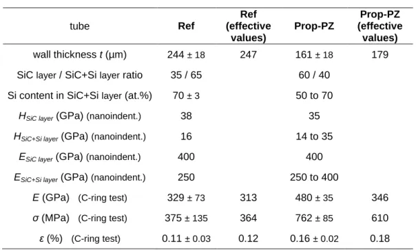
The use of a preheating zone of the gases before entering the deposition chamber and propene as an additional carbon source increases the proportion of pure SiC in the coating (Fig. 5). The ratio of the pure SiC layer to the total wall thickness is about 35% for Ref tube whereas it is nearly 60% for Prop-PZ tube (Tab. 1). The Si/C ratio decreases gradually in the SiC+Si outer part layer of Prop-PZ tube, from a silicon content of about 70 at.% at the surface to 50 at.% at the interface with the SiC layer. Compared with Ref tube, fSi is therefore significantly lowered when propene is added in the gas phase.
The degree of crystallization of the SiC phase in the pure SiC layer deposited without preheating zone is significantly higher than when obtained with the PZ and C3H6 addition. The Raman spectrum of the Ref specimen indeed shows sharp and intense peaks in the transverse optical (TO) region around 790 cm-1, which are typical of large columnar grains (Fig. 6a) [20-21, 23]. The absence of these marked features in the spectra of coatings deposited with both PZ and propene suggests the occurrence of coherent SiC domains of smaller size or containing a higher density of grain boundaries or stacking faults [23-24]. The difference in the SiC grain size is clearly confirmed by comparing two (111) dark field TEM images at same magnification of the pure SiC part in both Ref (Fig. 6b) and Prop-PZ specimens (Fig. 6c). The SiC coating has a columnar microstructure and is (111)-textured in both cases but the length and width of the largest columns are 3 to 5 times less in Prop-PZ than in Ref. Such a distinct microstructure is likely related to a different nature of the gas phase influencing the SiC nucleation and growth process. MDCS is expected to be significantly decomposed at 800°C for a residence time of 3 s, so that the gas mixture entering the CVD chamber essentially consists of saturated and relatively stable Si and C precursors such as SiHCl3, SiCl4, and CH4 [11]. The concentration of radical intermediates near the substrate is, in this case, much lower than when MDSC is directly introduced in the CVD reactor. The absence of radicals directly derived from the MDCS decomposition (SiHCl2, SiCl2, CH3), which are supposed to be involved in the crystal growth [25], thus appears to be detrimental to the SiC crystalline state.
3.2 Local mechanical properties - nanoindentation
The Young’s modulus (E) and hardness (H) radial depth profiles measured by nanoindentation along a cross section of Ref tube reveal two distinct parts, confirming the layered nature of the tube wall (Fig. 7). The lower properties are obviously due to the presence of free silicon, which is a much more compliant and soft material than SiC. Such a difference in the properties might also be related to a microstructural effect. H is indeed expected to vary with the SiC grain size. In submicrometer grain-sized SiC ceramics, the hardness usually follows an inverse Hall-Petch behavior, i.e. H decreases with the grain size [26]. The difference in hardness of the two distinct parts of the coating can be noticed in Figs. 7.a-c, from the difference in the print size left by the nanoindenter. Similar nanoindentation
profiles were obtained with Prop-PZ tube (not presented). The local mechanical properties in each layer are reported in Tab. 1. The gradual composition change in the SiC + Si part of Prop-PZ leads to E and H radial gradients. In the highest silicon concentration part of both tubes, the hardness is about 15 GPa and the Young’s modulus about 250 GPa. For comparison, the hardness is 35-38 GPa and the Young’s modulus is about 400 GPa in the SiC layer. These values are similar to those obtained from pure SiC, either as a 3C single-crystal [27] or a polycrystalline CVD coating [28].
Each E value can be precisely related to the local free silicon volume fraction fSi deduced from the chemical composition profile recorded by EPMA (Fig. 8). The E values decrease linearly with fSi. The regression line obtained (with a coefficient of determination R2 equal to 0.89) evidences that E obeys a simple "parallel" rule of mixtures:
E = fSi ESi + (1 – fSi) ESiC = (ESi - ESiC) fSi + ESiC
where ESiC and ESi are the Young’s modulii of SiC and Si respectively, i.e.
ESiC ≈ 400 GPa and ESi ≈ 130 GPa, in reasonably good agreement with values from the litterature [27-29].
3.3 Macroscopic thermo-mechanical properties – simulation and experimental testing of the C-ring specimens
3.3.1 Room temperature behavior
The macroscopic mechanical properties obtained from C-ring tests (Young’s modulus
E and failure stress σ and strain ε) for each tube should be considered as apparent
structural properties (Tab. 1). It clearly appears that the E value for Prop-PZ is overestimated since it is higher than for pure SiC. Since E is inversely proportional to the wall thickness cubed (t = R-r, equation (2), Fig. 1), the calculated value is strongly affected by wall thickness uncertainties. The influence of t is also expected to alter the failure stress values for the C-rings.
To bypass possible t inaccuracies, the apparent Young's modulus of the C-ring structure was calculated by FE modeling by imposing a vertical compression displacement ∆ and substituting the resultant reaction force ∆P in Equation 2. Each finite element was assigned a local E level depending on its through-thickness position, as measured by nanoindentation (Fig. 7). Calculated values of E = 313 and 346 GPa were obtained respectively for the Ref and Prop-PZ tube. These macroscopic E values, deduced by both nanoindentation and FE analysis, were then used to calculate the effective wall thicknesses (t) assumed from equation (2) (Fig. 1). The stress and strain at failure (respectively σ and ε) were then recalculated using the corrected t value (Tab. 1).
The experimental failure strengths obtained from the C-ring tests are scattered. σ is typically comprised between 200 and 600 MPa for Ref tube. This dispersion can originate from a broad flaw size distribution, as expected in brittle ceramic materials. Moreover, despite all the precautions taken, new surface defects may have arisen from the machining of the C-ring lateral edges.
The SEM-SE observation of the overall fracture surface of a Ref C-ring specimen emphasizes the bilayer morphology (Fig. 9.a). On the one hand, the outer SiC + Si layer exhibits a rather flat and smooth fracture surface with a slightly granular but very fine morphology at high magnification, typical of nanocrystalline ceramics
(Fig. 9.c). However, ripples oriented perpendicular to the growth direction can be observed on the outer part. These ripples correspond to the slightly lesser silicon excess revealed by the EPMA profile (Fig. 3.a), which is also probably associated with a coarser microstructure. On the other hand, the inner SiC layer exhibits a rougher fracture surface that can be related to its columnar microstructure, the crack being partially deviated along the grain boundaries (Fig. 9.b).
The failure strength obtained from the Prop-PZ C-rings is higher than for the Ref tube. Two assumptions can be made to explain this: (i) the degree of crystallization of the inner layer, which is in high proportion (SiC/SiC + Si ≈ 60/40) in Prop-PZ tube, is lower than in Ref tube, (ii) the two tubes lead to C-ring samples with a different residual stress state. Because of the different nature of the two layers and their distinct coefficients of thermal expansion (CTE), residual stresses are expected to occur within the layers after high temperature synthesis and cooling down at room temperature. The residual stresses were calculated by FE analysis across the thickness of the coating using the E and CTE profiles deduced respectively by nanoindentation measurements and the rule of mixtures. The coating was supposed to be purely elastic and deposited at a temperature of 1200°C (the zero-stress state). The residual stresses in the O-ring were first evaluated by imposing a uniform thermal loading of ∆T=-1200°C. These residual stresses were then transferred to the C-ring FE model as an initial stress field: they result in a force imbalance which induces a deformation of the C-ring specimen to eventually reach the mechanical equilibrium. The resulting self-equilibrated stresses correspond to the remaining thermal residual stresses after the C-ring being machined at room temperature.
A Young’s modulus ESiC of 400 GPa, a Poisson’s ratio of 0.2 and a CTE of 5 x 10⁻⁶ K-1 were used for the pure SiC internal layer [21, 30]. For the SiC + Si external part of the coating, the thermoelastic constants were estimated from simple rule of mixtures [31], the silicon volume fraction varying from 0 to 0.55 (Fig. 8). The resulting values for fSi = 0.55 are ESiC+Si = 250 GPa, SiC+Si = 0.2 and
CTESiC+Si = 3.9 x 10⁻⁶ K-1. At room temperature, the two relatively homogeneous layers of Ref tube lead to two nearly constant hoop stress levels in the inner and outer parts of the cross section (Fig. 10). The outer part of Ref tube is in compression (≈ -180 MPa) whereas the inner part is in tension (≈ 280 MPa). The composition profile of Prop-PZ results in a constant tensile stress level of ≈ 100 MPa in the nearly stoichiometric inner part of the coating and a steep decreasing gradient outwards, which reaches a strong compressive peak stress (≈ -300 MPa) at the outer surface. The balance of forces implies that the amplitude of stress within a layer increases when the relative thickness decreases. This stress state is not maintained when the tubes (or the O-rings) are cut into the C-ring samples. Once notched, the residual stresses partly relax elastically and the C-rings spontaneously get distorted. The diameter reduction of the C-ring is deduced by the FE analysis from the relative displacement of two opposite contact nodes. Values of 260 and 215 µm are obtained respectively for Ref and Prop-PZ. The machining of the C-ring results in a redistribution of the hoop stress radial profiles across the walls. The new stress distributions have been calculated for C-ring samples cut from the Ref and Prop-PZ tubes (Fig. 10). The stress profiles become more complex, turning to a saw tooth-like shape. The amplitude of the stress variation is reduced of about 25% for both specimens after machining. It is worthy of note that the outer surface of the SiC + Si layer is in tension in the Ref C-ring whereas it was initially in compression in the Ref tube. In contrast, the external surface of the Prop-PZ C-ring remains in compression
(Fig. 10). The latter case is naturally in favor of the room temperature failure strength of the C-rings in compression. Their outer surface is indeed gradually submitted to a maximum strain in tension along the wall thickness during the test. Such a different stress state could be responsible for the better failure properties for the Prop-PZ C-rings than for the Ref specimens. It clearly appears from this analysis that the C-ring geometry is not the most appropriate to characterize multilayer tubular structures, as it results in a particularly complex redistribution of the hoop stress state.
3.3.2 High temperature behavior Thermal expansion
Two temperature cycles were applied to the C-rings to better evidence irreversible phenomena. A significant positive residual displacement is observed after cooling down at the end of the first cycle, of 40 and 210 µm at 100°C for the Ref and Prop-PZ specimens respectively (Fig. 11). This residual strain of the specimen is associated with strong increase in the slope of the displacement curve during the first heating cycle beyond 1000°C, as well as during the dwell at 1200°C.This behavior is not due to the thermal expansion itself but likely results from the viscous flow of the Si-rich part of the coating activated at high temperature. This irreversible viscous deformation is thought to be a consequence of the relaxation of internal thermal stresses and/or microstructural changes. These processes are stopped on cooling, resulting in regular polynomial thermal expansion curves. The more prominent irreversible behavior of the Prop-PZ C-ring is surprising since the thickness ratio of the Si rich layer is less than in the Ref specimen. This phenomenon could result from the smaller SiC crystallites in this sample, as evidenced by TEM (Fig. 6c). Such a fine microstructure is more sensitive to creep and structural instability at high temperature than that the Ref sample. It is hence more affected by viscous flow and SiC coarsening during the first heating cycle and before reaching structural stabilization upon cooling.
The irreversible behavior is less pronounced in the second cycle showing a residual displacement three to ten times lower than in the first cycle. The irreversible phenomena are likely almost fully completed after the first cycle and have virtually no concequence on the following cycle. It is therefore reasonable to assume that the deformation measured during the second cycle is only due to thermoelastic phenomena (i.e. to thermal expansion and possibly also elastic strain). The displacements measured from 400°C to 1000°C during the second cycle are ∆δ = 68 µm and 110 µm, resulting in apparent CTE values of 14x10-6
K-1 and 25x10-6 K-1 for the Ref and Prop-PZ C-rings respectively. These values are unexpectedly high compared with the CTEs of pure Si and SiC, which are about 3x10⁻⁶ K-1 and 5x10⁻⁶ K-1, respectively. The CTE of the C-rings, far beyond these two limits, are obviously not the intrinsic values expected for homogeneous SiC + Si based materials. Such high values are rather apparent values of the bilayer specimens made of two materials of different thermoelastic properties. A FE analysis of the C-ring was achieved inferring the local elastic properties from the Si volume fraction. The apparent CTE of the C-ring was estimated by prescribing a unit thermal loading and measuring the corresponding diameter variation. The values obtained are 33x10-6 and 27x10-6 K-1 for Ref and Prop-PZ C-rings respectively, in reasonable agreement with the experimental results. This reversible phenomenon originates from
a structural effect, the well known bimetal principle used in bimetallic thermometers [32].
Elastic modulus
This analysis consists in measuring the deflection of a C-ring submitted to load cycling at low stress (0.5-10 MPa). The behavior of the C-rings is purely elastic up to 1000°C (no elongation is measured at a constant load of 10 MPa versus time during 30 s). At 1100°C and more markedly at 1200°C, a viscoelastic behavior is observed for both the Ref and Prop-PZ specimens. It is characterized by primary creep deformation at 10 MPa and recovery at 0.5 MPa. The creep strain rate is low enough, however, to extract the elastic component form the elongation curve. The influence of the temperature on the elastic modulus E of the Ref and Prop-PZ C-ring samples is shown in Figure 12. A first apparent drop is observed at a temperature as low as 500°C for both specimens. This unexpected result could be due to slight changes in the positioning of the specimen during the first loading cycles, as suggested by the high data dispersion at room temperature. E then dramatically decreases in both cases as the temperature increases beyond 800°C (Fig. 12). This high temperature behavior is similar to that of CVD-SiC monofilaments containing an excess of Si [21]. The stiffness of the SiC + Si material decreases exponentially as the temperature approaches the silicon melting temperature (Tm = 1410 C). An increase of E is observed reversibly on cooling down to room temperature, but up to only 800°C. No significant change of E is noticed from 800°C to room temperature on cooling. This more logical result tends to confirm that the initial low-temperature drop of E on heating was probably not intrinsic to the material but rather due to some sliding of the C-ring specimens between contacts at the beginning of the experiment. As the decrease of E, the viscoelastic behavior of the C-rings appearing beyond 1000°C can be assigned to the presence of free silicon. The elastic stress in the SiC + Si coating is relaxed by the viscous flow of silicon while the SiC coating further deforms elastically due to reloading.
Creep
The C-ring specimens were submitted to creep tests at incremental temperature. The creep curves recorded under a load of 100 MPa (Fig. 13) show the total elongation versus time, without reset at t = 0 (the non-isothermal elongations between each temperature dwell are not presented). A negative displacement on the curves corresponds to a closing of the C-ring edges. It is worth mentioning that the C-rings open during the heating ramp from one to the other higher temperature dwell. This behavior is due to the same above mentioned bimetal effect.
A creep deformation of the Ref C-ring is detected only from 1100°C and becomes very pronounced at 1200°C. The C-ring deflection Δδ reaches a value of 250 µm after ten hours at 1200°C. At this temperature, the curve follows a power-law typical of a primary creep stage showing a regular decrease of the creep rate versus time. This behavior is also likely due to the bilayer structure of the sample. The creep-sensitive SiC + Si layer readily relaxes the stress and leads to a reloading through elastic deformation of the creep-resistant SiC layer.
A significant creep deformation is observed beyond 1000°C in the case of the Prop-PZ C-ring. The sample collapses at 1200°C, with a total deflection of more than 500 µm after 10 h. The C-ring specimen is found flattened at the end of the test
indicating a high ductility of the material at high temperature. Such a poor creep resistance, despite the lower amount of free silicon compared to the Ref C-ring specimen, is probably related to the lower degree of crystallization of the SiC phase in the stoichiometric part of the coating. TEM analyses indeed revealed a significantly smaller SiC grain size in this part of Prop-PZ (Fig. 6). The creep rate in these fine-grained polycristalline CVD-SiC materials is usually limited by diffusional transport of matter at the grain boundaries [33]. Because of reduced diffusion distances, the smaller grain size of Prop-PZ results in a lower creep resistance compared to Ref sample [34]. This type of microstructure is not necessarily detrimental to a high temperature use, especially when associated to the creep resistant fiber reinforcement of a CMC (e.g. the Hi-Nicalon type S). On the contrary, it could bring some ductility and thus preserve the imperviousness of the SiC composite structure in incidental conditions in nuclear systems.
4. Conclusion
SiC tubes of several hundreds of microns thick and several tenths of centimeters long were obtained by continuous chemical vapor deposition (CVD) at atmospheric pressure inside a silica tube. The free standing CVD-SiC tubes were directly separated from their SiO2 substrate thanks to a favorable coefficient of thermal expansion mismatch and the deposition of a thin pyrocarbon interphase prior to that of the thick CVD-SiC layer.
The use of a standard CH3SiHCl2/H2 precursor leads to a bilayer SiC + Si (outer) / SiC (inner) coating. This inhomogeneous radial concentration profile results from the local change of temperature and residence time during continuous deposition. The highly reactive Si-rich gas species readily formed in the gas phase get gradually depleted as they progress along the sliding hot zone.
The installation of a preheating zone (PZ) of the gas precursors upstream of the deposition chamber and the addition of propene significantly improved the proportion of pure SiC in the overall thickness of the tube. The microstructure and the thermomechanical properties of the reference (Ref) and the improved CVD-SiC tube obtained using the PZ and propene addition (Prop-PZ) were characterized and compared. The elastic properties (E) were evaluated locally by nanoindentation and the macroscopic mechanical behavior was investigated from C-ring specimens cut from the tube. Finite element analysis helped to understand the experimental results of the thermomechanical tests.
As expected, the inner pure SiC region of the Ref specimen is coarser-grained and stiffer (E ≈ 400 GPa) than the SiC + Si region (E ≈ 250 GPa). The differences in E and CTE (respectively 5 x 10⁻⁶ and 3.9 x 10⁻⁶ K-1) lead to strong residual hoop stresses in the tube wall at room temperature. The outer SiC + Si part of the tube is in compression (≈ -180 MPa) whereas the inner pure SiC part is in tension (≈ 280 MPa). They are redistributed but not fully relaxed after the O-rings being cut into C-rings. This particular stress state likely affects the room temperature failure properties of the C-rings, in favor of the Prop-PZ specimens. It is also responsible for an unexpectedly high apparent CTE (≈ 25 x 10-6
K-1) related to stress relaxation on heating, according to a typical bimetal effect.
Probably owing to distinct effective precursors and growth mechanism, the pure SiC part of the coating is less crystalline in Prop-PZ than in Ref sample. This difference in microstructure explains the paradox of the creep resistance of Prop-PZ compared to
Ref: although containing significantly less free silicon, the former is more prone to irreversible strain and creep at high temperature.
Acknowledgements
This work was supported by the French Alternative Energies and Atomic Energy Commission (CEA) and the National Center for Scientific Research (CNRS) through a grant given to P. Drieux. The authors are indebted to T. Calais who participated actively to the experimental work. They also thank B. Humez for performing the C-ring tests at room temperature as well as C. Lorrette, P. David and A. Allemand from CEA for fruitful discussions.
References
[1] R. Naslain, Design, preparation and properties of non-oxide CMCs for application in engines and nuclear reactors: an overview, Comp. Sci. Technol. 64 (2004) 155-170.
[2] R.J. Kerans, R.S. Hay, N.J. Pagano, TA Parthasarathy, The role of the fiber-matrix interface in ceramic composites, Am. Ceram. Soc. Bull. 68 (1989) 429-442.
[3] A. Sommers, Q. Wang, X. Han, C. T'Joen, Y. Park, A. Jacobi, Ceramics and ceramic matrix composites for heat exchangers in advanced thermal systems-A review, Appl. Therm. Eng. 30 (2010) 1277-1291.
[4] E.V. Dyomina, P. Fenici, V.P. Kolotov, M. Zucchetti, Low-activation characteristics of V-alloys and SiC composites, J. Nucl. Mater. 258-263 (1998) 1784-1790.
[5] R.H. Jones, L.L. Snead, A. Kohyama, P. Fenici., Recent advances in the development of SiC/SiC as a fusion structural material, Fusion Eng. Des. 41 (1998) 15-24.
[6] R.H. Jones, L. Giancarli, A. Hasegawa, Y. Katoh, A. Kohyama, B. Riccardi, L.L. Snead, W.J. Weber, Promise and challenges of SiCf/SiC composites for fusion energy applications, J. Nucl. Mater. 307-311 (2002) 1057-1072.
[7] H. Feinroth, B.R. Hao, Multi-Layered Ceramic Tube for Fuel Containment Barrier and Other Applications in Nuclear and Fossil Power Plants, Patent W02006/076039, 2006.
[8] L. Chaffron, C. Sauder, C. Lorrette, L. Briottet, A. Michaux, L. Gelebart, A. Coupe, M. Zabiego, M. Le Flem, J.-L. Séran, Innovative SiC/SiC composite for nuclear applications, EPJ Web of Conferences 51 (2013) art. No. 01003.
[9] P.R. Smith, M.L. Gambone, D.S. Williams, 0.1. Garner, Heat treatment effects on SiC fiber, J. Mater. Sci., 33 (1998), 5855-5872.
[10] O. Féron, G. Chollon, F. Dartigues, F. Langlais, R. Naslain, In situ kinetic analysis of SiC filaments CVD, Diamond Relat. Mater. 11 (2002) 1234-1238. [11] P. Drieux, G. Chollon, S. Jacques, A. Allemand, D. Cavagnat, T. Buffeteau,
Experimental study of the chemical vapor deposition from CH3SiHCI2/H2: Application to the synthesis of monolithic SiC tubes, Surf. Coat. Technol. 230 (2013) 137-144.
[12] W.C. Oliver, G.M. Pharr, An improved technique for determining hardness and elastic modulus using load and displacement sensing indentation experiments, J. Mater. Res. 7 (1992) 1564-1583.
[13] M.K. Ferber, V.J. Tennery, S.B. Waters, J. Ogle, Fracture strength characterization of tubular ceramic materials using a simple c-ring geometry, J. Mater. Sci. 21 (1986) 2628-2632.
[14] O.M. Jadaan, D.L. Shelleman, J.C. Conway Jr., J.J. Mecholsky Jr., R.E. Tressler, Prediction of the strength of ceramic tubular components. Part I. Analysis, J. Test. Eval. 19 (1991) 181-191.
[15] D.L. Shelleman, O.M. Jadaan, J.C. Conway Jr., J.J. Mecholsky Jr., Prediction of the strength of ceramic tubular components. Part II. Experimental verification, J. Test. Eval. 19 (1991) 192-200.
[16] ASTM C1323-10, Standard test method for ultimate strength of advanced ceramics with diametrally compressed C-ring specimens at ambient temperature.
[17] W.G. Zhang, K.J. Hüttinger, CVD of SiC from methyltrichlorosilane. Part I: Deposition rates, Chem. Vap. Dep. 7 (2001) 167-172.
[18] W.G. Zhang, K.J. Hüttinger, CVC of SiC from methyltrichlorosilane. Part II: Composition of the gas phase and the deposit, Chem. Vap. Dep. 7 (2001) 173-181.
[19] F. Loumagne, F. Langlais, R. Naslain, S. Schamm, D. Dorignac, J. Sévely, Physicochemical properties of SiC-based ceramics deposited by low pressure chemical vapor deposition from CH3SiCl3H2, Thin Solid Films 254(1995) 75-82. [20] T.T. Cheng, l.P. Jones, R.A. Shatwell, P. Doorbar, The microstructure of sigma
1140+SiC fibres, Mater. Sci. Eng. A, 260 (1999) 139-145.
[21] G. Chollon, R Naslain, C. Prentice, R.A. Shatwell, P. May, High temperature properties of SiC and diamond CVD-monofilaments, J. Eur. Ceram. Soc. 25 (2005) 1929-1942.
[22] V. Radmilovic, U. Dahmen, D. Gao, C.R. Stoldt, C. Carraro, R. Maboudian Formation of (111) fiber texture in 3C-SiC films deposited on Si(100) substrates, Diamond Relat. Mater. 16 (2007) 74-80.
[23] Y. Ward, R.J. Young, R.A. Shatwell, Microstructural study of silicon carbide fibres through the use of Raman microscopy, J. Mater. Sci., 36 (2001) 55-66. [24] E. López-Honorato, C. Brigden, R.A. Shatwell, H. Zhang, I. Farnan, P. Xiao,
P.Guillermier, J. Somers, Silicon carbide polytype characterisation in coated fuel particles by Raman spectroscopy and 29Si magic angle spinning NMR, J. Nucl. Mater. 433 (2013) 199-205.
[25] F. Loumagne, F. Langlais, R. Naslain, Reactional mechanisms of the chemical vapour deposition of SiC-based ceramics from CH3SiCI3/H2 gas precursor, J. Cryst. Growth 155 (1995) 205-213.
[26] S. Guicciardi, D. Sciti, C. Melandri, A. Bellosi, Nanoindentation characterization of submicro- and nano-sized liquid-phase-sintered SiC ceramics, J. Am. Ceram. Soc. 87 (2004) 2101-2107.
[27] G.-S. Chung, K.-B. Han, H2 carrier gas dependence of Young's modulus and hardness of chemical vapor deposited polycrystalline 3C-SiC thin films, Microelectron. J. 39 (2008) 1413-1415.
[28] X. Li, B. Bhushan, Micro/nanomechanical characterization of ceramic films for microdevices Thin Solid Films 340 (1999) 210-217.
[29] L. Chang, L. Zhang, Mechanical behaviour characterisation of silicon and effect of loading rate on pop-in: A nanoindentation study under ultra-low loads, Mater. Sci. Eng. A 506 (2009) 125-129.
[30] S.K. Reddy, S. Kumar, R.N. Singh, Residual stresses in silicon carbidezircon composites from thermal expansion measurements and fiber pushout tests, J. Am. Ceram. Soc. 77 (1994) 3221-3226.
[31] C. Dong, Development of a model for predicting the transverse coefficients of thermal expansion of unidirectional carbon fibre reinforced composites, Appl. Compo Mater. 15 (2008) 171-182.
[32] P.R.N. Childs, Practical Temperature Measurement, Chap. 3 Bimetallic thermometers, 2001 p. 69-77.
[33] C.A. Lewinsohn, L.A. Giannuzzi, C.E. Bakis, R.E. Tressler, High-Temperature Creep and Microstructural Evolution of Chemically Vapor-Deposited Silicon Carbide Fibers, J. Am. Ceram. Soc., 82 (1999) 407-413.
[34] J.A. DiCarlo, Creep Limitations of Current Polycrystalline Ceramic Fibers, Comp. Sci. Technol., 51 (1994) 213-222.
Figure captions
Figure 1: Geometry of a C-ring specimen according to the ASTM C1323-10 standard [16].
Figure 2: Longitudinal temperature and growth rate profiles (a) and Raman profile along the tube axis (b) in static configuration
Figure 3: Radial depth atomic concentration profile across the wall of Ref tube obtained in continuous configuration, as measured by EPMA (a) and Raman profile of the same specimen (b)
Figure 4: SEM-BSE observation of Ref tube wall cross polished section (a) and TEM observation of the SiC+Si part, in SAD (b) and dark field (c) modes, and of the pure SiC part, in SAD (d) and bright field (e) modes.
Figure 5: SEM-BSE cross section observation (a), EPMA (b) and Raman radial depth profiles (c) of Prop-PZ wall.
Figure 6: Raman spectra (a) and (111) dark field TEM images of the SiC internal layers in Ref (b) and Prop-PZ (c) specimens.
Figure 7: Optical microscopy observation of nanoindentation prints in the (a) global studied area, (b) SiC inner part and (c) SiC+Si outer part and (d) Young’s modulus (E) and hardness (H) radial depth profiles measured by nanoindentation from Ref tube.
Figure 8: Young’s modulus measured by nanoindentation vs. Si volume fraction fSi deduced from EPMA, for both Ref tube and Prop-PZ tube.
Figure 9: SEM-SE observations of the fracture surface of a Ref tube C-ring specimen: (a) overall bilayer wall, (b) SiC layer part and (c) SiC + Si layer part.
Figure 10: Calculated residual hoop stress in the samples vs. normalized radial depth across the walls at room temperature, after processing at 1200°C before machining (tubes or O-rings) and after machining (C-rings).
Figure 11: Thermal expension curves for Ref and Prop-PZ C-ring samples (two heating & cooling cycles were achieved consecutively).
Figure 12: Normalized apparent Young’s modulus (E/ERT) vs. temperature for C-ring samples Ref and Prop-PZ.
Figure 13: Δδ vs. time under a load of 100 g for C-ring samples (a) Ref and (b) Prop-PZ
Table tube Ref Ref (effective values) Prop-PZ Prop-PZ (effective values) wall thickness t (µm) 244 ± 18 247 161 ± 18 179 SiC layer / SiC+Si layer ratio 35 / 65 60 / 40
Si content in SiC+Si layer (at.%) 70 ± 3 50 to 70
HSiC layer (GPa) (nanoindent.) 38 35
HSiC+Si layer (GPa) (nanoindent.) 16 14 to 35
ESiC layer (GPa) (nanoindent.) 400 400
ESiC+Si layer (GPa) (nanoindent.) 250 250 to 400
E (GPa) (C-ring test) 329 ± 73 313 480 ± 35 346
σ (MPa) (C-ring test) 375 ± 135 364 762 ± 85 610
ε (%) (C-ring test) 0.11 ± 0.03 0.12 0.16 ± 0.02 0.18
Table 1: total wall thickness, thickness layer ratio, Si content in the SiC+Si layer, local mechanical properties obtained from nanoindentation tests in both SiC and SiC+Si layers (hardness and Young’s modulus) and mechanical properties obtained from
Figure 1
Figure 2
Figure 3
Figure 4
Figure 5
Figure 6
Figure 7
Figure 8
Figure 9
Figure 10
Figure 11
Figure 12
Figure 13
![[PDF] Apprendre à Faire du HDR avec Photomatix PRo - Cours informatique](data:image/gif;base64,R0lGODlhAQABAIAAAP///wAAACH5BAEAAAAALAAAAAABAAEAAAICRAEAOw==)