A Distributed Embedded Software Architecture
for Multiple Unmanned Aerial Vehicles
by
Michael J. Matczynski
Submitted to the Department of Electrical Engineering and Computer Science
in partial fulfillment of the requirements for the degree of
Master of Engineering in Electrical Engineering and Computer Science at the
MASSACHUSETTS INSTITUTE OF TECHNOLOGY May 2006
@
Michael J. Matczynski, MMVI. All rights reserved. The author hereby grants to MIT permission to reproduce and distribute publicly paper and electronic copies of this thesis documentin whole or in part.
/D o
Author .... ] .: ...-.,.-.- .... .... I.,~..v . . ,w, ... Department of Elect cal En ineering and Computer Science
May 18, 2006 C ertified by.. .... ... ...
Jonathan P. How Associate Professor, Department of Aeronautics and Astronautics , ,Thesis Supervisor Accepted by ... ... ...
Arthur C. Smith Chairman, Department Committee on Graduate Students
OF TECHNOLOGY
-AUG 14 2006
ARCHIVES
A Distributed Embedded Software Architecture for Multiple
Unmanned Aerial Vehicles
by
Michael J. Matczynski
Submitted to the Department of Electrical Engineering and Computer Science on May 18, 2006, in partial fulfillment of the
requirements for the degree of
Master of Engineering in Electrical Engineering and Computer Science
Abstract
In order to deploy intelligent, next-generation applications on Unmanned Aerial Ve-hicles (UAVs), we must first develop a software architecture that supports onboard computation and flexible communication. This thesis presents an Onboard Planning Module developed from an embedded PC/104 Linux-based computer that commu-nicates directly with the UAV's autopilot to retrieve telemetry data and update the UAV's flight path. A serial communication program exchanges data with the UAV's autopilot while a multithreaded module enables concurrent onboard Mixed-Integer Linear Programming (MILP) optimization. The Mission Manager Graphical User Interface (GUI) monitors the status of each Onboard Planning Module on a team of UAVs using the onboard planning protocol. Two task assignment scenarios are simulated to demonstrate the system operating with both a single and multiple UAV task selection algorithm.
Thesis Supervisor: Jonathan P. How
Acknowledgments
Thanks to Prof. Jonathan How and James Paduano for providing me with the op-portunity to explore the intersection between aerospace engineering and computer science in the Aerospace Controls Laboratory.
To Mr. Ron Lensmire, my middle-school algebra teacher, who taught me that attitude is everything in life.
To my friends who have taught me more than any amount of schooling.
And last but not least, to my parents, who have supported and encouraged me without fail in all my endeavors.
This research was funded by the Air Force STTR phase I program #AF05-TO11, grant #FA9550-05-C-0131, with Sharon Heise as the technical monitor.
Contents
1 Introduction and Background 9
1.1 Overall Goal ... ... 10
1.1.1 Autopilot Communication from Linux ... 10
1.1.2 Onboard MILP Computation . ... 10
1.1.3 Payload Communication Protocol ... 11
1.1.4 Distributed Task Assignment Scenarios . ... 11
1.1.5 Mission Manager GUI ... ... 11
1.2 Past Work ... ... 12
1.3 Monocoupe Aircraft ... ... .. 12
1.4 Piccolo Autopilot ... ... 13
1.4.1 Waypoints and Plans ... .... 14
1.4.2 Operator Interface ... ... 15 1.4.3 Program Port ... ... 16 1.4.4 Payload Port ... ... . 16 1.4.5 Piccolo Streams ... ... 16 1.5 PC/104 Architecture ... ... 18 1.5.1 Tiny886ULP ... . ... .. 18
1.6 Mixed-Integer Linear Programming ... 19
2 Onboard Planning Module 20 2.1 System Architecture ... ... 21
2.1.1 UAV Architecture ... ... 21
2.2 PC/104 Hardware ... 21
2.3 Linux on the PC/104 ... 23
2.4 CPLEX on the PC/104 ... ... . 24
2.5 Remote PC/104 Access via SSH and FTP . ... 24
2.6 Seriall04 Board ... 25
2.7 Piccolo Communication Implementation . ... 25
2.7.1 Serial Program Overview ... .. 26
2.7.2 Cross-Platform Development . ... 26 2.7.3 Endian . . . . . . .. . . 27 2.7.4 Communication Buffers. . ... .. 27 2.7.5 CRC Calculation ... 27 2.8 CPLEX Integration ... 28 2.8.1 Mercator Projection ... 29
2.9 Onboard Planning Protocol ... 29
2.9.1 System-Defined Packets ... 30
2.9.2 User-Defined Packets ... 31
3 Mission Manager 32 3.1 User Interface . . . 33
3.1.1 Communication Configuration . ... 33
3.1.2 UAV Team Designation ... 34
3.1.3 Target Specification ... ... 34
3.1.4 Mission Management ... 34
3.2 Design and Implementation ... 35
3.2.1 Connecting to the Operator Interface . ... 35
3.2.2 Windows Timers ... 35
3.2.3 Processing the Autopilot Stream . ... 36
3.2.4 Processing the Payload Stream . ... 36
4 Experiments and Results 38
4.1 Hardware-in-the-Loop Simulation Testbed . ... 39
4.2 User-Defined Payload Packets ... .... ... . . 39
4.3 Single UAV Scenario ... ... 40
4.3.1 Scenario Overview ... 40
4.3.2 Results . . . .. . 41
4.4 Distributed Multi-UAV Scenario ... .. 43
4.4.1 Scenario Overview ... 43
4.4.2 Onboard Hardware Requirements . ... 44
4.4.3 Target Selection Algorithm ... 45
4.4.4 R esults . . . .. . 45
4.5 PC/104 Power Requirements ... 47
4.6 CPLEX Performance Comparison ... . . . . 48
5 Contributions 50 5.1 Future W ork . .. ... ... ... ... 51
List of Figures
1-1 Monocoupe 90A UAVs ...
1-2 Cloud Cap Technology's Piccolo Plus Autopilot [5]
1-3 Cloud Cap Technology's Operator Interface . . ..
1-4 1-5 2-1 2-2 2-3
Layers of Piccolo Communication . . . . PC/104 Embedded Computer System . . . . System Architecture . . . . PC/104 Connected to the Piccolo Autopilot Payload Packet Header . . . . 3-1 Mission Manager GUI . . . . 4-1
4-2 4-3 4-4 4-5
Single UAV Scenario Progression Over Time . . PC/104 and Laptop Simulation Setup . . . . Multiple UAV Scenario Progression Over Time . PC/104 Power Requirements ... PC/104 Performance Comparison ... *.. 12 .. 13 .. 15 .. 17 .. 19 .. 22 .. 23 .. 29 .. 33 . . . . . 42 . . . . . 44 . . . . . 46 . . . . 48 . . . . 49
List of Tables
1.1 Monocoupe specs (Figure 1-1) . ... . .. . . . . . 13
Chapter 1
Introduction and Background
Unmanned Aerial Vehicles (UAVs) provide the ability to perform tasks too dangerous or mundane for humans. In militaristic applications, UAVs effectively serve as long-endurance platforms for data collection and have been used for reconnaissance during recent wars and conflicts. In the present fight against terrorism, the United States military has used UAVs to patrol hostile areas of Afghanistan and Iraq, to seek out enemies, and to deliver missiles to targets. At home, the Predator B drone aircraft helps to combat illegal immigration by patrolling the border [1, 2].
UAVs can also be used in non-militaristic applications such as surveillance of infrastructure and acquisition of data. Because disasters often impair communication abilities by destroying infrastructure, UAVs are currently being developed to quickly restore utilities such as phone and Internet services [3]. UAVs are also used to inspect long stretches of remote pipelines or locate traffic accidents on major interstates.
Due to their relatively low cost, multiple UAVs can be used in activities that are coordinated, yet decentralized. However, coordination and cooperation requires reliable communication, which is a challenging design goal in hostile and ever-changing environments [4].
1.1
Overall Goal
The purpose of this project is to develop a software architecture to support decen-tralized and distributed missions on multiple UAVs. An embedded Linux PC/104 computer installed on each UAV will provide an Onboard Planning Module that en-ables the calculation of optimal flight paths and the completion of assigned tasks, even in the event of communication outages. This Master of Engineering thesis aims to solve many of the challenges posed by the implementation of this hardware and software system.
To operate properly, the Onboard Planning Module must communicate with the UAV's autopilot to monitor flight status, perform Mixed-Integer Linear Programming optimizations onboard, and communicate with other UAVs and the ground. A GUI must be developed to monitor the onboard status of the UAV, and task assignment scenarios must be developed to ensure correct operation.
1.1.1
Autopilot Communication from Linux
The Aerospace Controls Lab at MIT uses the Cloud Cap Technologies' Piccolo [5] as an autopilot for the UAVs. Unfortunately, software libraries required to communicate with the autopilots are provided only in binary format and for the Microsoft Windows platform. Thus, it is first necessary to develop an implementation of the Cloud Cap Piccolo Communications Protocol [6] to run on the Linux-based embedded computer.
1.1.2
Onboard MILP Computation
One goal of the system is to develop the infrastructure necessary to run Mixed-Integer Linear Programming (MILP) optimization problems onboard a UAV. To accomplish this task, an embedded computer will be installed into the payload of the UAV that has enough computational power to run retime task assignment and planning al-gorithms.
1.1.3
Payload Communication Protocol
A task may require the cooperation of multiple UAVs, so the software and hard-ware infrastructure should scale to allow a large number of vehicles to participate simultaneously. A key component in achieving this goal is a communication protocol that enables onboard planning and control algorithms to coordinate both with other nearby UAVs and with the Mission Manager GUI on the ground.
1.1.4
Distributed Task Assignment Scenarios
To test the system, a single UAV task assignment scenario will be developed and uploaded onto the embedded system. This scenario will have a single UAV receive a list of potential target locations and select the minimum distance target based on the UAV's current position and velocity. The system will communicate with the UAV's Piccolo autopilot to set a new waypoint at the chosen target. This scenario will test the integration of onboard MILP computation with the onboard planning protocol. The result will be an autonomous UAV that continuously listens for target locations sent from the Mission Manager GUI and approaches the one it selects as optimal.
Next, a distributed multi-UAV scenario will be developed. This scenario will require a number of UAVs to cooperatively assign each UAV to a target. The task of picking the optimal UAV/target matches will be distributed across the UAVs. Each UAV will calculate a list of its best targets and send the list to the other UAVs to determine the globally optimal assignment of tasks. Inter-UAV communication will be tested in this scenario. Section 4.4 describes the distributed scenario and target selection algorithm in more detail.
1.1.5
Mission Manager GUI
A Graphical User Interface (GUI) will be developed to control the task assignment scenarios by coordinating the start of a task and monitoring each UAV's progress in completing that task.
Figure 1-1: Monocoupe 90A UAVs
1.2
Past Work
Much of the research conducted in the past has focused on developing UAV architec-ture that supports a limited number of UAVs. Recently, research has been done to investigate and test various structures for multi-vehicle coordination [8].
Coordination of a fleet of UAVs is often a complicated optimization problem. Past research has focused primarily on breaking the large problem of controlling a UAV into two parts, task assignment and trajectory calculation. However, despite this simplification, these algorithms still perform too slowly to be used real-time in a dynamically changing battlefield environment. Recent work by M. Alighanbari demonstrates a novel approach called the Receding Horizon Task Assignment (RHTA) algorithm [9]. This algorithm produces near-optimal results, yet is computationally less expensive than past approaches. While it has only been tested in a lab, the algorithm may be light enough to run in real-time onboard a UAV.
1.3
Monocoupe Aircraft
The Onboard Planning Module is designed to be installed into the payload of the Kangke 1/4 scale Monocoupe 90A-based UAV. Past lab experiments used the Tower-Hobbies Trainer 60 aircraft, but more payload space was needed for bulkier equipment
Figure 1-2: Cloud Cap Technology's Piccolo Plus Autopilot [5] such as the PC/104 embedded computer and future camera.
The PC/104 with power supply has a mass of 1.0 kg and consumes under 10W of power under normal operation. To run for two hours, the embedded computer will require 0.8 kg of Lithium Polymer batteries. Power requirements are described more fully in Section 4.5.
Table 1.1: Monocoupe specs (Figure 1-1) Weight Wingspan Length Payload Cap Endurance Airspeed 18 pounds 96 inches 65 inches 5 pounds (internal) 2 hours 15 m/s - 30 m/s
1.4
Piccolo Autopilot
Cloud Cap Technology's Piccolo2 autopilot will be used to autonomously provide low-level guidance to the UAVs. Each Piccolo consists of a single-board MPC555
2
microcontroller that runs stabilization and waypoint guidance code.
The Piccolo autopilot works in an integrated way with a number of other hardware and software components. To communicate with the ground, the Piccolo autopilot uses a 900 MHz wireless link to send and receive information from the Piccolo ground station. The Piccolo ground station converts information from the 900 MHz link to an attached ground station computer running the Piccolo Operator Interface (Section 1.4.2) and Mission Manager GUI (Section 3). In the laboratory, the Piccolo autopilot can be attached to a simulation computer via the CAN bus to enable hardware-in-the-loop testing, as described in Section 4.1.
The Piccolo autopilot can operate in a variety of different modes, but only the multi-homed mode meets the requirements of this project. In this mode all commu-nication sent from the Piccolo onboard the UAV to the ground station is also sent to the Piccolo's external RS-232 serial port, also called the program port. The on-board Linux PC/104 computer will listen and communicate over this serial connection operating at 57.6k baud to:
* Retrieve information from the Piccolo autopilot such as aircraft telemetry * Send updated waypoints and plans to change the aircraft's trajectory
Multi-homed operation allows the Linux PC/104 computer to update the UAV's flight plan while still permitting a user on the ground to track and monitor the status of the aircraft. Additionally, to ensure safety an operator on the ground can relinquish control from the Onboard Planning Module at any time by using the Piccolo Operator Interface.
1.4.1
Waypoints and Plans
The Piccolo autopilot controls an aircraft along a trajectory determined by a series of waypoints. A unique index number between 0 and 99 references each waypoint, consisting of latitude, longitude, and altitude. A flight plan consists of a closed, ordered listing of waypoints.
mm
Audio
icdo 1 P 1940:1:7 25 . a..
Aero Terrrination
TelemetryI Commands Map Preflight Limits
Alt 150.2[m] TAS 200 [m/s] Vin 11.9 T['C]47 RSS-71 RPM4772 WP 3 Send' Flight plans Cursor mode Mouse position From ground station New multipoint * Select -"In Lat N 44iI1 6523 [deg] Range 8784.83 [km]
I]
CD
al
Figure 1-3: Cloud Cap Technology's Operator Interface
While the UAV is in flight, the Piccolo autopilot tracks a single waypoint and attempts to approach it. When the waypoint is reached, the tracking waypoint will change to the next waypoint in the flight plan, and the process repeats.
The Onboard Planning Module developed in this project will dynamically change waypoint locations and entire flight plans based on the results of task planning and assignment algorithms run onboard the UAV.
1.4.2
Operator Interface
The Piccolo Operator Interface software program (Figure 1-3) monitors the status of a number of UAVs by listening to data sent from each aircraft's Piccolo autopilot. State information for the UAVs is displayed to the user on the ground station computer.
Each Piccolo autopilot broadcasts telemetry data to the Operator Interface at 1 Hz or 20 Hz, and the same data is received by the Onboard Planning Module via the program port. The Operator Interface can monitor multiple aircraft simultaneously
SNew quick pl, New land plai
Edit. Dele
Requestl Sen
Save Oper
SLocal Co f Remote
Add image layer
Add vector layer
Scw-close.tilf
and display their positions on a map.
In addition to the Operator Interface GUI allowing a user to monitor the aircraft, it also exports all information it receives from the Piccolos to a TCP/IP server port on the local machine. Thus, a custom GUI such as the Mission Manager described in Section 3 can connect to the Operator Interface TCP/IP port and receive the same state information.
1.4.3
Program Port
Two RS-232 serial ports are required to connect the PC/104 to the Piccolo. The first is the "program" serial port. This serial port mirrors all data that is transferred between the Piccolo and the ground station's Operator Interface. It is used to retrieve state information such as GPS latitude, longitude, and altitude from the Piccolo. Additionally, waypoints can be sent to the Piccolo to update the UAV's intended flight plan.
1.4.4
Payload Port
The Piccolo autopilot's second serial port allows the transfer of user-defined data. In the course of building a virtual ground station onboard the aircraft, information must be communicated between a GUI on the ground and the PC/104 onboard. Section 2.9 describes the design and implementation of the onboard planning protocol used to control the Onboard Planning Module, set up simulations, and provide inter-UAV and UAV-ground communication.
1.4.5
Piccolo Streams
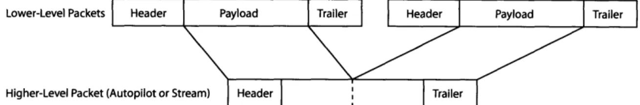
The Cloud Cap Piccolo sends and receives data using multiple bidirectional streams that are multiplexed onto the 900 MHz wireless channel. The communication protocol defines a number of stream types in Table 1 of Piccolo Communications [6], though the Onboard Planning Module will only need knowledge of the autopilot stream and payload stream. Data is sent between endpoints, which can be either Piccolo
Lower-Level Packets
Higher-Level Packet (
Figure 1-4: Layers of Piccolo Communication
autopilots or the Operator Interface. Two levels of packets exist to provide different functionality.
Lower-level packets serve as the transport layer. This layer simply moves data from one endpoint to another in small blocks. As it is only a transport mechanism for stream data, multiple lower-level packets may need to be combined to form a complete higher-level packet, as shown in Figure 1-4.
Higher-level packets transfer data for streams such as the autopilot stream and payload stream. For example, autopilot stream packets carry system commands from the Operator Interface to the autopilot and sensor telemetry information from the au-topilot to the Operator Interface. Although a single higher-level packet is well-formed and can be used directly, it can also be used to encapsulate additional communica-tion protocols. Seccommunica-tion 2.9 demonstrates using payload stream packets to support an additional protocol used by the Onboard Planning Module.
Error Handling
Error checking on stream data is handled using both exclusive or (XOR) checksums and Cyclic Redundancy Checks (CRCs). On the lower layer of communication, the transport layer, each stream packet header contains an 8-bit XOR checksum on bytes 0-12 (See Table 2 in Piccolo Communications [6]). This early check allows a receiv-ing machine to determine if the header is valid and enables rapid detection of bad synchronization (SYNC) characters.
In addition to XOR checksums, CRCs are also used to check for errors in data transmission. Both levels of packets contain a 16-bit CRC. The CRC16 algorithm used produces a 2 byte value for validation. At the lower level, the CRC applies to all
the data. The higher level, autopilot or payload stream, also uses a CRC that covers the entire packet length. This second CRC is necessary because data in one autopilot packet may be transported using multiple lower-level transport packets. Thus, this higher-level CRC ensures that the Piccolo Communications implementation correctly receives and reassembles the data.
If a packet's XOR checksum or CRC is invalid, the receiving machine discards the packet.
1.5
PC/104 Architecture
The PC/104 form factor allows boards of size 3.6" x 3.8" to be stacked vertically to form a compact and powerful computing solution onboard an unmanned aerial vehicle. PC/104 gets its name from the number of pins used to connect different boards together, which electrically uses the standard PC ISA (Industry Standard Architecture) bus. Different types of boards such as CPU, serial interface, graphics, and coprocessor boards can be stacked together to allow great flexibility in size and functionality.
1.5.1
Tiny886ULP
The Onboard Planning Module uses the Tiny886ULP PC/104 CPU board from Ad-vanced Micro Peripherals shown in Figure 1-5. The CPU board has a 1.0 GHz Cru-soe processor with 512 MB of RAM. A secondary board contains a CompactFlash connection, which allows a CompactFlash card to act as an IDE hard drive due to DiskOnChip technology. To aid in debugging, the Tiny886ULP has connectors for VGA, ethernet, keyboard, and mouse, though these peripherals will be disconnected when the Onboard Planning Module is deployed onboard the UAV.
Figure 1-5: PC/104 Embedded Computer System
1.6
Mixed-Integer Linear Programming
Mixed-Integer Linear Programming (MILP) is an optimization technique that allows for minimizing a piecewise-linear objective function subject to linear and logical con-straints. Such a formulation has recently been applied to path planning, where its piecewise linear nature enables fast convergence for real-time application, and its integer nature allows for expressing logical constraints useful for obstacle avoidance.
One example of a MILP problem used onboard an aircraft is target location se-lection. For example, an aircraft may have a number of target locations from which to pick and would like to select the optimal one based on some objective. A MILP optimization problem could be formulated to take the targets along with the aircraft's position and velocity and return a result indicating the best target to approach first. In this application, the aircraft's Onboard Planning Module will use telemetry data read from the Piccolo's program port as input to an optimization problem. ILOG CPLEX 9.0 will be used to solve MILP problems onboard the UAV. A user on the ground will be able to monitor and control MILP optimizations via the Mission
Chapter 2
Onboard Planning Module
In order to enable intelligent computation on a UAV, an Onboard Planning Mod-ule was designed and developed. This Onboard Planning ModMod-ule serves as a virtual ground station to control the flight path of the UAV based on the results of running task planning and assignment algorithms. However, unlike previous implementations that involve running computationally expensive algorithms on the ground and com-municating the results to the UAV, all computation is performed onboard the aircraft. Thus, the Onboard Planning Module must communicate the UAV's plan and status to the user on the ground.
During normal operation, the following programs run on the onboard embedded computer:
* ILOG CPLEX and License Manager Daemon(ilmd) (Section 2.4) * Piccolo Serial Communication Program (Section 2.7)
Based either on messages from the user-controlled GUI (Section 3) on the ground or on the state of the UAV in the air, the serial communication program may begin a CPLEX optimization. Once computation completes, the results are used by the on-board planning algorithm to change Piccolo waypoints, thus modifying the flight path of the UAV. The Onboard Planning Module continuously sends status information back to the GUI on the ground.
2.1
System Architecture
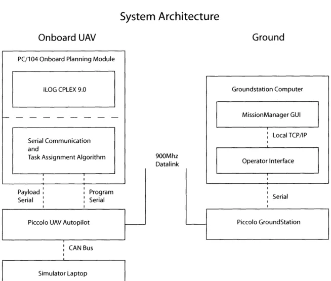
Figure 2-1 shows the architecture of both the UAV and ground systems necessary to enable onboard computation. Although the figure displays only a single UAV communicating with the ground station (over the 900 MHz wireless Piccolo link), this architecture scales to support multiple UAVs communicating with the same ground station.
2.1.1
UAV Architecture
The UAV system consists of a PC/104 embedded computer running Red Hat Linux 9.0. Key system software includes ILOG CPLEX 9.0, the serial communication pro-gram, and a user-defined task assignment algorithm. This embedded computer com-municates with the Piccolo UAV autopilot using the payload and program RS-232 serial ports described in Section 1.4.3. Figure 2-1 also illustrates the optional connec-tion to the simulator laptop which enables hardware-in-the-loop testing of the system on the ground. This method of testing is further described in Section 4.1.
2.1.2
Ground Architecture
The ground system consists of a Piccolo ground station connected to a laptop running Cloud Cap Technology's Operator Interface (Section 1.4.2) and Mission Manager GUI (Section 3). The Mission Manager connects to the Operator Interface in order to communicate with the Piccolos, as described in Section 3.2.1.
2.2
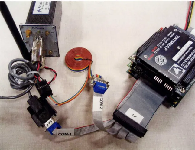
PC/104 Hardware
The Onboard Planning Module is built using a PC/104 embedded computer system with two serial ports to communicate with the Piccolo autopilot, as shown in Figure 2-2. An Advanced Micro Peripherals Tiny886ULP running Red Hat Linux 9.0 com-prises the base for the Onboard Planning Module. This embedded computer has a 1.0 GHz Crusoe processor, which is comparable in performance to an AMD Athlon
System Architecture
Onboard UAV
900Mhz DatalinkGround
Serial I CAN Bus Simulator LaptopFigure 2-1: System Architecture
PC/104 Onboard Planning Module
ILOG CPLEX 9.0
Serial Communication and
Figure 2-2: PC/104 Connected to the Piccolo Autopilot
or Intel Pentium-III, and 512MB of RAM. A Serial I/O board is installed in the PC/104 stack to provide the two RS-232 serial ports needed to communicate with the Piccolo's program and payload ports. A 1.0 GB CompactFlash disk serves as non-volatile storage and suffices to store Red Hat Linux 9.0, ILOG CPLEX 9.0, the serial communication program, and task assignment algorithm.
2.3
Linux on the PC/104
Although the PC/104 is compatible with all major operating systems including Win-dows, Red Hat Linux 9.0 was chosen due to its performance, reliability, flexibility, and relatively small size. The standard distribution of Red Hat Linux 9.0 contains the two system libraries required by ILOG CPLEX 9.0, glibc 2.3 and gccc 3.2.
at-tached to the PC/104 and a bootable Red Hat Linux 9.0 CD was used to install Linux. The PC/104's non-standard CompactFlash/IDE drive required manually specifying parameters for the IDE device's cylinders, heads, and sectors (C/H/S). The "Mini-mum" installation set of packages was chosen, consuming approximately 750 MB of the 1.0 GB CompactFlash disk.
2.4
CPLEX on the PC/104
ILOG CPLEX 9.0, Concert Technologies, and the ILOG License Manager were in-stalled in:
/usr/ilog/
Because the Onboard Planning Module is designed to continue operation even in the event of a network outage, a stand-alone, single-user ILOG license was installed. The PC/104 was registered with ILOG and the license file was placed in:
/usr/ilog/ilm/
The ILOG license manager daemon ilmd
runs on bootup and grants access to CPLEX requests from the local machine.
2.5
Remote PC/104 Access via SSH and FTP
To aid in development and debugging, the PC/104 was configured to allow remote SSH and SFTP sessions. The Tiny886ULP's built-in ethernet port was configured to obtain an IP address dynamically via DHCP. Additionally, the firewall that comes preinstalled with Red Hat 9.0 was modified to allow incoming SSH and SFTP con-nections.
2.6
Serial104 Board
The PC/104 must communicate with both the program and payload serial ports on the Piccolo autopilot. Although the PC/104 development kit provides two serial ports, the Seriall04 communication controller from Advanced Micro Peripherals was added to the PC/104 stack to provide eight RS-232/RS-422 serial ports to support future peripherals such as an onboard camera.
One of the challenges of getting the Seriall04 card to work in Linux was compiling and installing a kernel-level device driver. Because the PC/104 had limited hard drive space, a separate computer running Red Hat Linux 9.0 provided a more comprehensive development environment. In addition to having the same libraries installed on the PC/104, this computer had all the kernel development libraries to allow the Seriall04 driver to build and link. Once compiled, the driver file (s104.o) was copied to the PC/104 via SFTP.
The following command installs the Seriall04 device driver as a kernel module: insmod s104.o IntO=15 Base0=0x100
Jumpers on the Seriall04 configure its interrupt and base I/O address. Next, the following commands install special character devices in the /dev directory:
mknod /dev/ttyAMPO c 204 32 mknod /dev/ttyAMP1 c 204 33
204 is the major device ID and the numbers 32 and 33 are the minor device ID, which range from 32 to 39 for the eight port Seriall04 card.
The following command removes the device driver from memory: rmmod s104
2.7
Piccolo Communication Implementation
Cloud Cap Piccolo Communication [6] specifies the protocol between the Piccolo avionics and and Piccolo ground station. Cloud Cap provides binary libraries for
Windows only. Although Cloud Cap makes the source code available for compiling under Linux, ITAR restrictions precluded its use and required a reimplementation.
2.7.1
Serial Program Overview
The PC/104's serial communication program is written in C++ and runs on both Linux and Windows. On the Linux-based PC/104 the program begins after bootup and loops continuously, listening for new data and responding to requests. Upon each iteration of the loop, the serial program services both the program and payload port serial connections.
Autopilot stream data travels between the PC/104 and Piccolo autopilot via the program serial port. When the serial communication program is launched, it opens the program communication port
/dev/ttyAMPO
The data on the autopilot stream is identical to that received by the Operator Inter-face on the ground as the Piccolo operates in multi-homed mode. On each iteration, the program listens for telemetry updates and system diagnostic updates from the Piccolo and records this state in memory.
The payload port transfers the user-defined payload stream governed by the on-board planning protocol between the PC/104 and Piccolo. The serial communication program handles this stream in the same way as the autopilot stream but responds to onboard planning protocol packets to configure the Onboard Planning Module, start a MILP computation, and deliver inter-UAV and UAV-ground messages. Section 2.9 describes the design and implementation of the onboard planning protocol.
2.7.2
Cross-Platform Development
The Linux Piccolo Communication implementation was first developed on Windows using Microsoft Visual Studio. Debugging on embedded Linux systems can be chal-lenging, but using the visual debugging environment of Visual Studio greatly short-ened development time.
The C++ source code was written to be cross-platform compatible on both Win-dows and Linux. Both implementations differ in the initial step of reading data from the two serial ports. Platform-dependent code initializes the serial port and polls for data periodically, placing new data in global buffers. After this point, implementa-tions on both operating systems operate identically. The code base diverges again only when writing to the serial ports.
2.7.3
Endian
The Cloud Cap Piccolo autopilot runs on an MPC555 microcontroller which differs from the PC/104's x86 architecture in handling data as the endian is reversed. Thus, the serial communication program must translate the Piccolo's big-endian data to x86 little-endian format. The serial program handles this transformation using the macros ENDIAN8(), ENDIAN16(), and ENDIAN32(), which reverse the order of multibyte data types. Functions such as EncodeWaypointPacket() and DecodeWay-pointPacket() hide the transformation of the Piccolo data structures from the user.
2.7.4
Communication Buffers
The serial communication program running on the PC/104 has three data buffers: one for the serial input, one for the autopilot stream, and one for the payload stream. Each buffer has a capacity of 4096 bytes.
Cloud Cap recommends checking for data on the serial port every 10-20ms. How-ever, because the Red Hat Linux kernel internally caches serial input and output, even if the serial communication program does not service the serial port within that interval, it is very unlikely for the system to lose data.
2.7.5
CRC Calculation
A cyclic-redundancy-check (CRC) is performed over both the stream packet data and individual packet data such as autopilot packets and payload packets. This implementation uses the CRC16 algorithm to generate a 16-bit CRC which is stored
as two consecutive bytes in the trailer of both the stream packet header as well as the autopilot stream packet header. The Cloud Cap specification indicates that packets with invalid CRCs must be discarded.
2.8
CPLEX Integration
MILP optimizations must be set up and run from the serial communication program without blocking the system. Thus, a multithreaded module was developed to run CPLEX from within the serial communication program. This module consists of a single class called "MILPHandler" which handles setting up the MILP problem using ILOG Concert Technologies, running CPLEX, and returning the results of the calculation. The Linux pthreads library provides multithreading capabilities.
The MILPHandler module has an interface defined by:
* bool RunMILP(void);
* time_t GetElapsedTime(void);
* bool IsMILPRunning(void);
To run a CPLEX optimization from the serial communication program, the first step involves setting input global variables. As described in Section 4.3, the Onboard Planning Module test scenarios consist of sending a series of potential target locations to the UAV and having CPLEX determine an optimal target by selecting the target with the minimum time required to reach it. Inputs into the optimization problem include the UAV's current position and velocity as well as the list of targets.
After the input has been set, the serial communication program calls RunMILP() to create a thread to run the CPLEX optimization concurrently. The serial com-munication loop continues communicating with the Piccolo autopilot and processing payload input, checking the value of IsMILPRunning() at every iteration. When this method returns false, the serial communication program retrieves the output from global variables, updates the aircraft's flight path by modifying Piccolo autopilot
Sync
Size
Type
User
DestO
Destl
SourceO
Sourcel
Byte 0 1 2 3 4 5 6 7
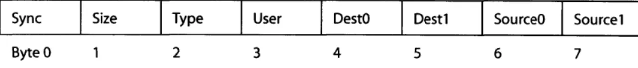
Figure 2-3: Payload Packet Header
waypoints, and sends a status message back to the Mission Manager GUI via the payload port.
2.8.1
Mercator Projection
The Piccolo autopilot represents position using latitude, longitude (both in degrees), and altitude (in meters). When creating MILP optimization problems, it is often con-venient to measure relative positions using meters, and thus a conversion routine [7] was implemented to handle transforming data in both directions.
2.9
Onboard Planning Protocol
The PC/104 communicates to the ground station computer via the Piccolo payload port which allows the transmission of arbitrarily formatted data. Thus, one of the challenges to enabling onboard computation is designing and implementing an efficient and flexible payload protocol.
The onboard planning protocol functions similarly to Cloud Cap's autopilot pro-tocol. Because all payload data is encapsulated and transferred by lower-level Piccolo packets that perform error checking, the system can safely assume that if a packet arrives at either end, no data corruption has occurred. Therefore, the protocol must be designed knowing that packets will either be delivered perfectly or dropped com-pletely.
An onboard planning protocol packet begins with an eight byte header as shown in Figure 2-3. A sync byte is used to ensure the packet is properly aligned. Next, the one-byte size field indicates the number of payload bytes in the packet, excluding the eight, bytes in the header. For example, a PAYLOAD_STATUS message carrying the string "OK" would have a length of two. Next, the type field specifies the function of
the packet as either a system-defined message such as PAYLOADSTATUS or as an application-specific message carried in PAYLOAD_UAV. Table 2.1 shows the possible values. A user byte allows application-specific messages to be exchanged. Source and destination fields specify the packet's endpoints.
The header contains a source and destination address to allow a UAV to send data to any UAV or the Mission Manager GUI. Similar to the Cloud Cap Communication address specification, this addressing scheme uses a two-byte value to specify the end points of the packet in the range of 0 to OxFFFF. A packet sent with a destination address of OxFFFF, the broadcast address, will arrive at all the UAVs. The address OxFFFE is reserved for the Mission Manager GUI.
Differing from Piccolo autopilot stream packets, onboard planning protocol pack-ets use little-endian format to keep the implementation simple. The Mission Manager and Onboard Planning Module both run on x86 hardware which natively supports little-endian, so transmitting data in the same format eliminates extra processing in the encode and decode parts of the payload protocol implementation.
2.9.1
System-Defined Packets
A number of onboard planning protocol packet types are defined to provide basic functionality such as modifying the state of the Onboard Planning Module, commu-nicating status messages to the Mission Manager GUI, and supporting user-defined inter-UAV and UAV-ground data exchange. Table 2.1 summarizes the types.
* PAYLOAD_OPM This packet allows a user on the ground to control the opera-tion of the Onboard Planning Module. From the ground, the Onboard Planning Module can be turned on or off. Additionally, settings such as the frequency of status messages sent to the ground can be changed.
* PAYLOAD_STATUS This packet sends a text status message from the Onboard Planning Module to the Mission Manager GUI. This packet begins with the header shown above and follows with a number of bytes, with the header size field indicating the number of characters in the status string. It should be noted
that this string is not null-terminated and the string length must be determined from the header.
* PAYLOADUAV This packet enables inter-UAV and UAV-ground communica-tion of arbitrary user-defined data. The header contains a single byte called "user" to allow application-specific message types. The flexibility of the PAY-LOAD_UAV packet allows it to serve as a transport layer to enable higher-level protocols to operate.
Currently the system requires all inter-UAV communication to travel through the ground station and Mission Manager, limiting scalability as the Cloud Cap ground station can only handle 115,200 baud, or around 11kb/sec. However, the lower-level Piccolo protocol is only used as a transport mechanism for the higher level PAYLOAD_UAV packets and thus can easily be switched to use a future technology to handle the transmission of PAYLOAD_UAV messages among UAVs in the air.
Table 2.1: Onboard Planning Protocol Packet Types
Packet Type ID Description Direction
PAYLOAD_OPM 0 Configure Onboard Planning Module Up PAYLOADSTATUS 1 Send text status message to Mission Manager Down
PAYLOAD_UAV 2 Inter-UAV Communication Both
2.9.2
User-Defined Packets
Combining the system-defined PAYLOAD_UAV packet with the header's user-defined byte allows great flexibility in customizing the types of messages sent between vehicles and the ground. The packets described in Section 4.2 demonstrate the simplicity of adding user-defined, application-specific types to support both single (Section 4.3) and distributed multi-UAV (Section 4.4) algorithms.
Chapter 3
Mission Manager
One of the challenges involved in designing an architecture for multi-UAV scenarios is developing a way to control and monitor the status of each UAV in a team. The ideal solution allows the operator on the ground much flexibility in managing missions and monitoring the status of the team.
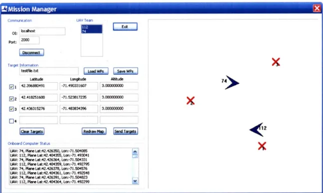
The Mission Manager Graphical User Interface (GUI) described in Section 3.1 and shown in Figure 3-1 allows a user on the ground to control and monitor single or distributed multi-UAV scenarios involving a task assignment algorithm. The scenario consists of one or more UAVs having the goal of arriving at a number of target locations. The Mission Manager GUI enables the user to graphically select target locations and broadcast them to the Onboard Planning Module onboard each UAV. Each UAV determines a list of optimal target locations and communicates these to the other UAVs with the help and coordination of the Mission Manager GUI. The user monitors and tracks the status of the UAVs from the ground.
The GUI was implemented using Microsoft Visual Studio .NET with C++ and MFC. The user interface is described next in Section 3.1 and the design and imple-mentation details are covered in Section 3.2.
Cornmunation UAV Team
01:• L:
2P000
Target Informatln
testfilebct
i
WPSLattude Langude Alttude
l1 42.396880491 -71.490331607 3.000000000
02 42.418251600 -71.523817235 3.00000000
P3 42.436315276 -71.483834396 3.000000000
n4
1<
Onboard Computer Status
UAV: 74, Plane Lat:42.426350, Lon:-71.504085
LUAV: 112, Plane Lat:42.404355, Lon:-71.493041 ULV: 74, Plane Lat:42.426364, Lon:-71.504331
UAV: 112, Plane Lat:42.404359, Lon:-71.492795
iUAV: 74, Plane Lat:42.426378, Lon:-71.504576 LUAV: 112, Plane Lat:42.404361, Lon:-71.492548 UIAV: 74, Plane Lat:42.426391, Lon:-71.504823
LiV: 112, Plne Lat:42.404364, Lan:-71.492299
Figure 3-1: Mission Manager GUI
3.1
User Interface
The GUI allows a user to configure Cloud Cap Piccolo communication, load and save target locations, designate a team of UAVs, begin the task assignment scenario, and monitor onboard status.
3.1.1
Communication Configuration
The GUI must establish communication with the Piccolo Ground Station in order to communicate with the team of UAVs. The user enters the hostname and port of the Operator Interface running on the computer connected to the ground station. When the Operator Interface runs on the same computer as the Mission Manager, the hostname of "localhost" is used. Pressing the "Connect" button contacts the Operator Interface and populates the list box of available UAVs.
3.1.2
UAV Team Designation
To support multi-UAV scenarios, the Mission Manager GUI allows a user to designate a team of UAVs to complete a task. The GUI displays a list of available UAVs, iden-tifying each one by its unique Piccolo autopilot number. Clicking the UAV number in the UAV list toggles its association with the current team. Team designation goes into effect at the start of the next mission.
3.1.3
Target Specification
The GUI displays an overview map of locations that are potential targets for a UAV team. Each target is indicated by a red X mark with an associated target identification number. Clicking a position on the map adds a new target location at that point.
To make testing easier and reproducible, the GUI can load and save target loca-tions from a file. When a user clicks the "Save Targets" button the GUI writes all checked waypoints to disk by saving the latitude, longitude, and altitude to a binary file with each element stored as a double. Clicking the "Load Targets" button reads the targets from disk and displays their positions on the map.
3.1.4
Mission Management
The Mission Manager GUI allows the user to begin and abort missions as well as monitor the status of the Onboard Planning Module during the mission.
To begin a mission the user presses the "Send Targets" button. This action reads the latitude, longitude, and altitude of all targets checked, inserts the data into a user-defined payload packet as defined in Section 4.2, and broadcasts this packet to each UAV in the team for processing by the Onboard Planning Module. Because the Mission Manager performs all communication periodically using a Windows timer as described in Section 3.2.2, clicking the "Send Targets" button simply sets a flag in the GUI's class to instruct the next invocation of the timer to read the data, form the payload target packet, and broadcast the packet to all UAVs selected as part of this mission.
During the mission, each UAV periodically reports its progress by sending status payload messages to the Mission Manager. The frequency of updates is controlled by one of the onboard planning protocol's system-defined messages described in Section 2.9. The GUI shows each message and associated UAV number in a status box. In addition to displaying information such as MILP computation times, the status box also shows errors and warnings from the onboard algorithms.
3.2
Design and Implementation
The Mission Manager GUI Dialog Box was developed using Microsoft Visual Studio .NET's Resource Editor. To communicate with Piccolo autopilots, the GUI uses a Windows binary release of Cloud Cap Technology's Communications library. A Windows timer polls the Communications library at a fixed interval to check for incoming data.
3.2.1
Connecting to the Operator Interface
The Operator Interface connects to the Piccolo ground station via RS-232 serial to communicate with a number of Piccolo autopilots. Additionally, the Operator Interface acts as a network server, listening for incoming TCP/IP connections on port 2000. When a TCP/IP client establishes a connection the Operator Interface acts as a bridge and transfers data in both directions between the Piccolo autopilots and the Piccolo ground station.
When a user presses the Connect button on the GUI the Mission Manager uses the Cloud Cap API to create a CCommManager object that connects to the Operator
Interface via TCP/IP at address localhost:2000.
3.2.2
Windows Timers
Cloud Cap Technology recommends polling the Piccolo ground station for data every 10-20 ms to ensure timely processing of incoming messages. Thus, upon connecting
to the Operator Interface the Dialog Box registers a timer callback function with Windows to run every 20 ms.
3.2.3
Processing the Autopilot Stream
To service an incoming request the timer first calls the CommSDK's RunNetwork() method to send and receive data. Next, the LookForAutopilotData() method checks for new Piccolo autopilot information, parses the information based on packet type, and updates global state information such as the position and velocity of a UAV. Although over 50 Piccolo autopilot packets are specified, the Mission Manager only needs the information in the following packets:
* TELEMETRY Provides the latitude, longitude, and altitude of the UAV * TRACK Indicates that the UAV is tracking a different waypoint
* WAYPOINT Moves the position of a waypoint to a new location
3.2.4
Processing the Payload Stream
Next, the OnTimer method processes payload stream data. This involves reading the packet format as defined in Section 2.9 and updating the GUI by adding status messages to the list box or updating the positions of the UAVs on the graphical map display.
Every invocation of the timer checks if the "send targets" flag has been set by the GUI. If it has, the timer first reads the target locations by querying the GUI's text fields using the GetWindowText() method of each list box. The latitude, longitude, and altitude of a particular target is only retrieved if its corresponding checkbox is enabled, which can be determined by calling GetCheck().
After the targets have been read from the Windows GUI controls, they are packed into a PAYLOADTARGETS packet as defined in Section 4.2. Once formed, the timer calls the Cloud Cap Communication API's SendBlock() method to send the packet to the set of UAVs in the team.
3.2.5
Reentrant Timers
After the program registers a timer callback, Windows runs the OnTimer() method every 20ms. Because calls to send and receive network data may block, in order to ensure correctness, a thread of execution locks a CRITICALSECTION upon entering the timer method. This locking procedure ensures that only one invocation of the timer runs at a time and prevents data corruption of global variables. If a newly invoked thread discovers that another thread already holds the lock, the newly invoked thread simply returns.
Chapter 4
Experiments and Results
To test the correctness of the system, both a single and multi-UAV scenario were developed. Both scenarios consist of UAVs selecting optimal targets from a list of target locations sent from the Mission Manager GUI and assigning each UAV to a target. The Hardware-in-the-Loop Simulation (Section 4.1) allowed testing of the On-board Planning Module and Mission Manager GUI from the ground on the following scenarios:
* Single UAV, Multiple Targets (Section 4.3) * Multiple UAVs, Multiple Targets (Section 4.4)
Both scenarios demonstrate the ease of adding user-defined payload packet types. Section 4.2 describes two packets that:
* Send a list of target locations from the Mission Manager to the UAVs
* Broadcast UAV results to other UAVs to reach a consensus on task assignment To quantify characteristics of the Onboard Planning Module, power consumption for the PC/104 embedded computer was measured under different states of operation in Section 4.5, and PC/104 CPLEX computation times were compared to other systems in Section 4.6.
4.1
Hardware-in-the-Loop Simulation Testbed
The Aerospace Controls Laboratory at MIT uses a hardware-in-the-loop simulation to test cooperative control algorithms on the ground. This setup greatly shortens development time and reduces the risk of flying untested software and hardware on real airplanes.
The simulation testbed consists of a number of Sony Vaio laptop computers run-ning simulation software from Cloud Cap Technology. These laptops communicate with the Piccolo autopilots over the CAN bus and simulation real-world flight param-eters such as aircraft position, aircraft velocity, and wind velocity. The simulation software can load state information from files to allow a scenario to easily be run multiple times.
During simulation, the Piccolo autopilots continuously broadcast state informa-tion on the 900 MHz channel. The Piccolo ground stainforma-tion communicates with multiple autopilots and allows the Operator Interface to connect and retrieve data. Thus, the status of multiple aircraft can be tracked simultaneously on a single ground station computer running Cloud Cap's Operator Interface software.
Previous work performed in the Aerospace Controls Laboratory focused on per-forming computation on the ground and sending the resulting plans to the autopi-lots [10]. Each Piccolo was assigned a Dell laptop where CPLEX optimizations would be performed. A program called CommunicationSDK ran on each of these laptops to communicate the results of MILP optimizations to MATLAB which eventually got sent to the autopilots.
4.2
User-Defined Payload Packets
In the single UAV scenario described in Section 4.3, the Mission Manager GUI must send a list of participating UAVs and a list of target locations to the Onboard Planning Module. Thus, the user-defined PAYLOADTARGETS packet described below sends this information.
In the multi-UAV scenario described in Section 4.4, in addition to receiving a list of potential target locations, multiple UAVs must coordinate their target selection. This process requires each UAV to broadcast the result of its onboard computation with all other UAVs. The task assignment algorithm sends an ordered listing of the time it would take to reach each available target to all other UAVs. Thus, an additional user-defined packet called PAYLOAD_UAVRESULT is used to exchange results.
* PAYLOADTARGETS This packet sends a list of UAVs and a list of waypoints from the Mission Manager GUI on the ground station computer to the PC/104 and begins a CPLEX optimization. The payload program sends each waypoint by taking the latitude, longitude, and altitude and writing the values into the data area of the payload packet. The latitude and longitude are each of type double (8 bytes) and the altitude is a float (4 bytes).
* PAYLOAD_UAVRESULT Once a UAV completes a series of MILP optimiza-tions, the task assignment algorithm packages the results into a new packet called PAYLOAD_UAVRESULT and broadcasts it to all other UAVs.
New payload packet types can easily be introduced to provide further functionality. However, for most purposes these packets provide the foundation needed to develop onboard distributed multi-UAV algorithms.
4.3
Single UAV Scenario
A single UAV scenario was developed to test the Onboard Planning Module's ability to receive information from the Mission Manager on the ground, perform a MILP optimization problem onboard, and update the UAV's flight path.
4.3.1
Scenario Overview
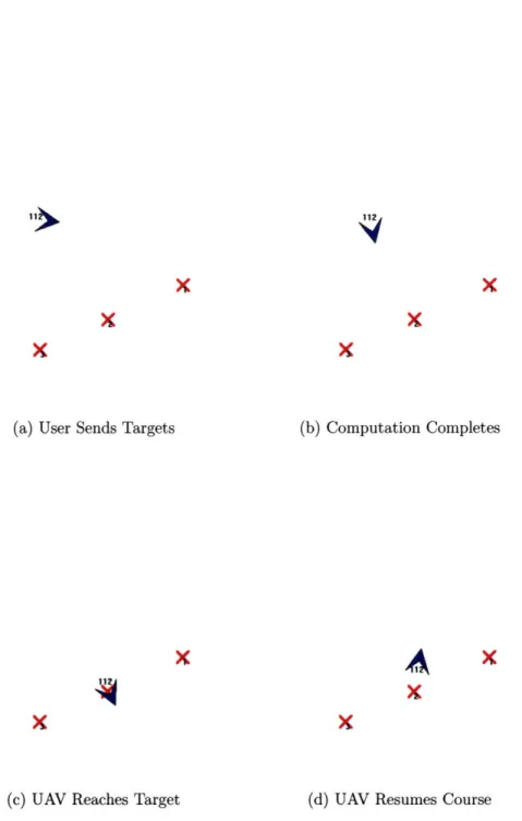
The single UAV scenario involves a UAV selecting an optimal target from a list based on the UAV's heading and velocity. As shown in Figure 4-1, the UAV begins at
the left side of the map heading east. After specifying three target locations using the Mission Manager GUI, the user clicks "Send Targets" to inform the UAV of the task. The list of target locations is sent to the Onboard Planning Module using the PAYLOAD_TARGETS user-defined packet. CPLEX then calculates the amount of time it would take to reach each of the targets and selects the locally-optimal taret as its goal. Finally, the Onboard Planning Module sends an updated flight plan to the Piccolo autopilot to approach the optimal target.
The single UAV scenario consists of the following steps:
1. The Mission Manager sends a list of target locations to the single UAV using the PAYLOAD_TARGETS packet. The number of targets is variable, though to keep the computation viable to perform in real-time most testing has limited it to four or fewer.
2. The Onboard Planning Module runs a CPLEX optimization to determine flight time to each target.
3. Once the optimization finishs, the Onboard Planning Module selects the target that can be reached in the shortest amount of time and instructs the Onboard Planning Module to approach that location. The Onboard Planning Module sends a Waypoint packet over the autopilot stream to update the UAV's flight path.
4.3.2
Results
Figure 4-1 shows the progression of the single UAV scenario over time. UAV 112 begins as shown in Figure 4-3(a), flying due east. At this time the user on the ground selects three targets and clicks the "Send Targets" button. The Mission Manager creates a PAYLOAD_TARGETS packet and sends it to UAV 112. The Onboard Planning Module begins calculating the amount of time it will take to approach each of the three targets.
Figure 4-1(b) shows the point at which the Onboard Planning Module selects target location 2 and reorients towards it. This maneuver is the result of the Onboard
I1
112b
(a) User Sends Targets (b) Computation Completes
A
(c) UAV Reaches Target (d) UAV Resumes Course
Figure 4-1: Single UAV Scenario Progression Over Time
Planning Module sending a waypoint packet to the Piccolo autopilot via the program port. When the UAV reaches the target and achieves its goal (Figure 4-1(c)), it resumes its original course as shown in Figure 4-1(d).
4.4
Distributed Multi-UAV Scenario
After the basic functionality of the Onboard Planning Module was tested with the sin-gle UAV scenario, a distributed multi-UAV scenario was developed to test the ability of the Onboard Planning Module and onboard planning protocol to support inter-UAV communication. Two inter-UAVs running in the Hardware-in-the-Loop simulator are used for testing distributed multi-UAV capabilities.
4.4.1
Scenario Overview
Similar to the single-UAV scenario, the multi-UAV scenario involves each UAV se-lecting its closest waypoint based on that UAV's heading and velocity. Two UAVs begin their mission as shown in Figure 4-3(a) and fly straight towards each other. The user sends targets to the UAV team and the same optimization problem as the single UAV scenario runs for each target. However, instead of simply picking the UAV's locally-optimal choice, each UAV communicates its results to all the UAVs on the same team before making a selection. A distributed target selection algorithm then assigns each UAV to a target and the autopilot is notified of the flight path change.
The distributed multi-UAV scenario consists of the following steps:
1. The Mission Manager sends a PAYLOADTARGETS packet to each UAV on the team. This packet contains a list of participating UAVs as well as a list of target locations.
2. The Onboard Planning Module runs a CPLEX optimization for each target to calculate a metric that indicates its desirability based on proximity.
3. Each UAV forms a PAYLOADUAVRESULT packet from its results and sends this packet to the Mission Manager GUI for routing.
Figure 4-2: PC/104 and Laptop Simulation Setup
4. The Mission Manager receives the PAYLOAD_UAVRESULT packet and broad-casts it to all other UAVs on the same team.
5. After a UAV receives all of its teammates' results, a target selection algorithm is run to assign each UAV to a target. This calculation is performed in parallel on each UAV. Because all UAVs have the same input, the resulting UAV/target pairings will be consistent across the entire team. The target selection algorithm is described in further detail in Section 4.4.3.
4.4.2
Onboard Hardware Requirements
The Aerospace Controls Lab currently only has a single PC/104 to operate as the Onboard Planning Module. To simulate a multi-UAV scenario, an identical version of Red Hat Linux 9.0, ILOG CPLEX, and the serial communication program were installed on a laptop. A Quatech serial interface PCMCIA card was added after com-piling drivers for Red Hat Linux 9.0 to provide the two RS-232 serial ports required to communicate with the Piccolo autopilot. The two Onboard Planning Modules connected to their respective Piccolo autopilots with optional simulation laptops are shown in Figure 4-2.
4.4.3
Target Selection Algorithm
The target selection algorithm used in the distributed, multi-UAV scenario aims to globally assign UAV/target pairings to approach targets as quickly as possible. Each UAV receives a unique target, thus maximizing target coverage.
Although more robust task assignment algorithms have been developed[9, 11, 12, 13], this simple algorithm successfully achieves its goal and serves as an example of running CPLEX optimizations onboard a UAV in real-time. The algorithm assumes that data transmission is lossless and all UAVs remain within communication range.
The distributed task assignment algorithm:
1. Receives all [approach time metrics, target ID, UAV ID] results. 2. Sorts results in increasing order of approach time to each target.
3. Selects the result with the shortest approach time metric and assigns that UAV ID to that target ID.
4. Removes all other results containing that UAV ID or target ID.
5. Repeats steps 3-4 until each UAV has a target, at which time the result list is empty.
In order for the distributed target selection algorithm to produce consistent results on different UAVs, the sorting in step 2 must perform in a systematic and determin-istic way. Results are first sorted by approach time. If approach times are equal, priority is given to the lowest Piccolo ID.
4.4.4
Results
Figure 4-3 shows the progression of the distributed, multi-UAV scenario over time. Two UAVs, 74 and 112, begin as shown in Figure 4-3(a), flying straight towards each other in steady level flight. At this time the user on the ground designates a team, selects three targets, and clicks the "Send Targets" button. The Mission Manager creates a PAYLOADTARGETS packet and broadcasts it to all the UAVs on the team. The Onboard Planning Module on each UAV begins calculating the amount of time it will take to approach the three specific targets.
7
<2
(a) User Sends Targets
X
(c) UAVs Change Course
(e) Goals Achieved
(b) Computation Completes
X
(d) UAVs Approach Targets
(f) UAVs Resumes Course Figure 4-3: Multiple UAV Scenario Progression Over Time

![Figure 1-2: Cloud Cap Technology's Piccolo Plus Autopilot [5]](https://thumb-eu.123doks.com/thumbv2/123doknet/14751668.580483/13.918.317.608.136.411/figure-cloud-cap-technology-s-piccolo-plus-autopilot.webp)