I
A )igrital Autopilot for the Space Shuttle Vehicle
t)by
Greg L. Zacharias
B.S., M.I.T.
(1967)
SUBMITTED IN PARTIAL FULFILLMENT OF THE REQUIREMENTS FOR THE
DEGREE OF MASTER OF SCIENCE
at the
MASSACHUSETTS INSTITUTE OF TECHNOLOGY February, 1974
Signature of Author
Department of Aeronautics
and Astronautics, February 1974 Certified by Certified by Accepted by Thesis Supervisor Thesis Supervisor ./ , t _ I _ _ I -- - - -Chairman, Departmental Graduate Committee Archives
\ .
A DIGITAL AUTOPILOT FOR THE SPACE SHUTTLE VEHICLE
by
GREG L. ZACHARIAS
Submitted to the Department of Aeronautics and Astronautics,
Massachusetts Institute of Technology, on January 15, 1974, in partial
fulfillment of the requirements for the degree of Master of Science.
ABSTRACT
A digital autopilot is designed for the Space Shuttle Vehicle (SSV),
for operation during atmospheric entry following deorbit, and system
performance is evaluated by flight simulation. A combination of design synthesis techniques is used to meet the performance specifications over the large entry flight envelope, and to ensure satisfaction of design
constraints imposed by control effector characteristics and uncertainties
in vehicle design. Autopilot design is based on a rigid-body, quasi-static, stability-axis linear model of the vehicle dynamics, which is derived from the general non-linear equations of motion. The simpli-city of this dynamic model provides for insight into design trades
re-garding control effector utilization and modes of stability-axis attitude
control. The control laws governing operation of the Attitude Control Propulsion System (ACPS) are based on this simplified model, and con-sist of several phase-plane switching logics which reflect the inertial characteristics of the vehicle during the early portion of the entry. The
control laws governing operation of the Aerodynamic Control Surface System (ACSS) are also based on the simplified vehicle model, and are
essentially linear networks whose gains are chosen by an analytic closed-loop pole allocation method. A novel feature of this linear logic is the deliberate use of turn miscoordination to effect banking maneuvers, a feature which substantially reduces ACPS fuel expenditures when
compared with conventional body-axis control techniques. A non-linear blending logic incorporated in the autopilot design ensures compatible operation between the ACPS and ACSS, and provides for a gradual
transition from exoatmospheric flight to flight characterized by conven-tional aerodynamic forces and torques. Extensive simulation through-out the flight envelope is used to validate the autopilot design, both for nominal operation and for operation in the face of vehicle and environ-mental uncertainties. The results show that the autopilot meets its
design goals, and suggest further avenues of analysis and design effort
needed prior to flight software implementation.
Thesis Supervisors:
John J. Deyst, Jr.
Associate Professor of Aeronautics
and Astronautics
Donald C. Fraser
Lecturer, Department of Aeronautics
and Astronautics
Director, Control and Flight
Dynamics Division, Charles Stark
ACKNOWLEDGEMENTS
I wish to express my gratitude to my thesis supervisors,
Professor John J. Deyst, Jr., and Dr. Donald C. Fraser, for their guidance, criticisms, and suggestions through the course of this design effort, and especially for their tactful hints regarding the completion
of the manuscript.
Engineering work on a project of this magnitude is never done in
a vacuum, and I am indebted to many co-workers at the Charles Stark Draper Laboratory (CSDL), the National Aeronautics and Space
Admin-istration Johnson Space Center (NASA/JSC), and the Houston Aerospace Systems Division of the Lockheed Electronics Company (LEC/HASD). In particular, at CSDL I thank Mr. Peter Weissman for his unfailing assistance with the digital implementation of the autopilot design, and Mr. Craig Work for both his patience in diagnosing system software problems I encountered and his continued support of the simulator soft-ware. In addition, at CSDL, thanks are due to Mr. Fred J. Marcus for his help in interfacing a guidance system with the autopilot, and to Mr.
J. Edwin Jones for a similar effort involving integration of a state estimator. The results presented here have early roots in my work at NASA/JSC, and I am indebted to Dr. Kenneth J. Cox and Mr. William
Peters for their guidance and support during the preliminary design
phases. Also at NASA/JSC, I thank Mr. Emory E. Smith for help with the many details which are involved in a project of this sort, and Mr. Jerrold H. Suddath for both his suggestions for design improvement
and his especially helpful comments on vehicle controllability. Finally, much of the early programming effort involved in digital implementation
of the autopilot was conducted by Mr. F. Eugene Volentine of LEC/HASD,
and I am grateful for his assistance.
This thesis would not have gone beyond the manuscript stage had
it not been for the excellent technical services provided by the CSDL personnel, in particular by Mr. William D. Eng and the Technical
Publications Group who rendered in final form the many figures
pre-sented here, and especially by Mrs. Karen Thomas Bergmann, Mrs. Margaret Conley, and Ms. Margaret Erickson, whose manuscript typing and editing abilities made the publication of this thesis a
TABLE OF CONTENTS
Chapter Page
INTRODUCTION . . . 10
2 DESIGN REQUIREMENTS . . ... . 16
2. 1 Vehicle and Flight Envelope ... . 17
2. 2 Sources of Control Authority . . . 25
2.2.1 ACPS
...
.
25
2.2.2 ACSS
...
.
26
2. 3 Performance Requirements . . . 35 2. 4 Off-Nominal Considerations . . . 38 2. 4. 1 Model Accuracy . . . 39 2. 4. 2 Subsystem Errors . . . 422. 5 Implications for Control System Design . . . 44
3 DESIGN SYNTHESIS OVERVIEW ... 49
4 VEHICLE MODEL . . . 5
4. 1 Linearized Equations of Motion .. . . 54
4. 1. 1 Non-Linear Equations of Motion . . . 54
4. 1. 2 Equilibrium Flight Equations . .. 58
4. 1. 3 Symmetric Flight Equations . . . 60
4. 1. 4 Aerodynamic Perturbations . . . 61
4. 1. 5 Linearized Dynamics (body-axis frame) ... 63
4.2 Stability- Axis Variables . . . .
4.3 Stability- Axis I otational )ynarn) ics . . .
4. 3. 1 ongittudintal Short-Period Dynamics
4.3.2 Lateral Short-Period Dynamics . .
4. 4 Simplified Model Summary . . . .
4. 4. 1 Longitudinal Dynamics . . . . .
4. 4.2 Lateral Dynamics . . . .
4. 4.3 Simplified Model Block Diagrams .
4. 4.4 Implications for Lateral Control .
CONTROL SYSTEM SYNTHESIS ....
5.1 Longitudinal Control . . . . ..
5. 1. 1 Pitch ACPS Control . .
5.1.2 Elevator Control . . .
5.2 Lateral Control . . . .
5.2. 1 Lateral ACPS Control .
5.2.2 Lateral ACSS
Control . .
5.3 Blending Logic . . . .
5. 3. 1 Longitudinal Blending Logic
5.3.2 Lateral Blending Logic .
5.4 Input/Output Processing . . . .
5.4. 1 Inputs . . . .
5. 4.2 Outputs . . . .
5. 5 Gain and Parameter Selection .
5. 5. 1 Fixed Parameters . ..
5.5.2 Scheduled Gains .
..
SUMMARY DESIGN DESCRIPTION . .
6. 1 Overview ...
6.2 Control System Description . . .
6.2. 1 Longitudinal Control
6. 2.2 Lateral Control . . . .
6. 3 Gain and Parameter Specification
6.4 Digital Implementation . . . .
...
.105
...
.109
...
110
...
115
... .. 123...
.124
...
.133
...
.173
...
.174
...
180
... .. 183...
.183
...
.193
...
.200
... .20 1 ... 2 14... 218
... 2 18...
.220
... .. . 22 1 ... .. 228... 238
...
.246
66 70 70 74 83 84 89 95 97 5 67 PERFORMANCE EVALUATION ... 247 7. 1 Simulator Description ... ... . 249
7.2 Performance in a Nominal Environment . . . 253
7.2.1 Transient Response ... 256
7. 2. 2 Operational Flight Envelope . ... 340
7.2.3 Systems
Integration
.
. . . . ... 353
7. 2. 4 Summary of Performance in a
Nominal Environment ... . 365 7.3 Performance in an Off-Nominal
Environment . . . ... 367
7.3. 1 Center-of- Gravity Displacements . . 369
7. 3 2 Variations in Aerodynamic
Coefficient Values . . . 3 85
7. 3. 3 Actuator Rate Limits . . . 398
7. 3. 4 Trajectory Parameter Estimation
Errors ...
.
..
...
402
7. 3. 5 Vehicle Attitude Estimation Errors. . 406
7. 3.6 Summary of Performance in an
Off-Nominal Environment . . . 408
8 SUMMARY AND RECOMMENDATIONS ... 410
Append ix
A STABILITY AND CONTROL DERIVATIVES . . . . 413
B NUMERICAL APPROXIMATIONS FOR A
SIMPLIFIED VEHICLE MODEL .... .... 418
C TRAJECTORY PARAMETER HISTORIES FOR
TYPICAL ENTRY MISSION . . . .. 470
D SAMPLED-DATA FORMULATION OF
EQUATIONS OF MOTION . . . ... 476
E FUEL-TIME OPTIMAL CONTROL OF A
DOUBLE-INTEGRATOR PLANT ... . 489
(; IA1 Ilt A1, (I IINII11- ()'I' - * 1XVITY 31
G fA 'l'Ili' V l OV I i'
(O)1i"'S 1 ,'!. . . . . . . .". 531
Ei ELEVATOlR/AILElON Al,l ,()CATION LOGIC . . 539
I LATERAL CLOSED- LOOP TRANSFER
F UNCTIONS . . . 546
j CONTROL SYSTEM FLOW CHARTS . ... 549
K AERODYNAMIC COEFFICIENT VARIATIONS
AND LATERAL CONTROLLABILITY . ... 560
LIST OF REFERENCES . . . 565
1. ntroduction
The objective of this study is to design and evaluate an automatic attitude control system for the Space Shuttle Vehicle
(SSV) for use during atmospheric entry after deorbit. It should be recognized that due to the magnitude of the SSV program, several engineering groups are actively involved in the autopilot design effort: The Johnson Spacecraft Center of the National Aeronautics and Space Administration (NASA-JSC), the Space Division of
Rockwell International (RI), the Aerospace Division of Honeywell
Incorporated (HI), and the C. S. Draper Laboratory (CSDL). This
thesis documents a portion of the CSDL effort in the SSV autopilot design area, and it should be noted that both complementary and parallel studies are being conducted by the other groups; in fact, an alternative approach to the entry control problem, developed by
RI and HI, is the present baseline design for eventual incorporation into the SSV flight software. The eventual decision to fly this
baseline design will, of course, depend on the system's performance in the face of the anticipated changes in vehicle configuration and mission requirements, between this point in time and the time of
the first launch (presently scheduled for early 1979). It should also be recognized that all of the groups mentioned above are
conducting on-going design efforts; in keeping with this dynamic situation the design discussed here will undoubtedly change to meet new requirements and/or improve performance. However, it is
felt that the design is of sufficient maturity to merit the documenta-tion this thesis provides, and that such a snapshot" view will give the reader a fair insight into the entry control design problem.
The entry flight phase is fairly loosely defined; here it is taken to be initiated when the vehicle's altitude drops below
400, 000 ft (at velocities in excess of 26, 000 ft/sec) and terminated at an altitude of approximately 75, 000 ft (with a velocity of
for SSV operation, they are all characterized by an eventual return from orbit to a conventional (dead-stick) airstrip landing, so as to reduce recovery and refurbishment costs. Compared with an
Apollo-type ocean recovery, the targeting requirements are
relatively stringent; to compensate, the delta-wing vehicle has a higher lift-to-drag ratio than the Apollo command module, so that the SSV may be viewed as more like an airplane than a typical blunt-body entry vehicle. With specific regard to the dynamic properties of the vehicle then, the entry portion of the mission can be viewed as a transition phase from exo-atmospheric operation in which the vehicle's mass properties dominate the dynamic response characteristics, to an atmospheric regime in which the aerodynamic
effects become considerably more significant. This factor, combined
with the objective of maintaining active attitude control throughout
the entry, is perhaps the driving influence in control systems
design, and the one which distinguishes this design problem from
those encountered in past projects (e. g., passive stabilization of
blunt-body rotational dynamics).
The altitude/velocity "corridor" flown by the SSV during
entry is basically similar to those flown by other entry vehicles. The similarity stops here though, because of the larger variable
lift-to-drag ratio allowing for considerable modulation of the vehicle's flight path. This capability is somewhat similar to X-15 operation, although the latter's flight envelope is significantly smaller due to the lower altitudes and velocities encountered at
entry interface. SSV operation differs from X-15 flight in another important aspect: high angle-of-attack operation. This feature is required to provide the necessary drag deceleration; the
implica-tions for aerodynamic control of the vehicle are significant,
simply because of the lack of flight experience with design-specified
The performance requirements placed on the attitude control system stem primarily from guidance specifications, while the design constraints can be traced to the vehicle, sensor, and control effector hardware specifications. In the former case, the guidance
system attempts to meet its targeting objectives, while satisfying
its design constraints, by modulation of the vehicle's angle-of-attack and bank angle throughout the entry. Thus, the control logic must be capable of commanding the appropriate control effectors, which consist of attitude control thrusters and aerodynamic control
surfaces, so as to maneuver the vehicle in a sufficiently responsive
manner to satisfy the guidance requests. Naturally, a subsidiary
control objective is to maintain or augment vehicle stability through-out the entry envelope. This capability is of course dependent on the actuators available to the control logic (e.g., ACPS thrust
levels, auxiliary control surfaces, etc. ), and, to a large extent,
on the aerodynamic characteristics of the vehicle.
The design philosophy guiding the development of the controller is fairly straightforward: after gaining a strong insight into the fundamental dynamics and constraints involved, break the problem down into easily identifiable design subtasks, and then, for each subtask, use any available design technique which shows promise in providing a solution. This problem-oriented approach naturally leads to an amalgamation of different design characteristics, and it is appropriate here to note some features of the control system design eventually arrived at. The control logic is digital, and is presently implemented in FORTRAN. The design utilizes both non-linear phase-plane switching logics (for control of the attitude jets) and gain-scheduled linear logics (for control of the aerodynamic control surfaces), with a "blending" logic to provide appropriate phasing between the two control effector subsystems. Mode
switching and non-linear filtering are used as appropriate, primarily
flight envelope (the magnitude o the flight envelope (can be
appreciated by tet rring to lhe i mission histories i llstral ing
Appendix C). Naturally, many of these features will change as the design continues to evolve in response to vehicle/mission/hardware changes; thus, the design presented here is a "snapshot" of the
entry control system in one stage of its development.
This study is organized into eight chapters. Chapter 2 provides a more formal definition of the design problem at hand, by
summa-rizing the important vehicle characteristics, flight-envelope
parameters, and performance requirements appropriate to control
system design definition. Aside from providing a quantitative
introduction to the problem, this information serves as a base for a discussion of some of the engineering trades involved in controller design; it also serves as a convenient reference source of data
relevant to the analysis and synthesis efforts of later chapters.
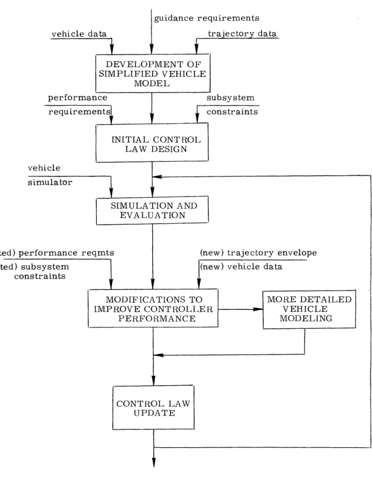
Chapter 3 then provides a brief overview of the design synthesis effort itself, in an attempt to provide a meaningful introduction to the quantitative material of the next three chapters. This chapter
stresses the iterative nature of the design process, with the
fundamental feedback provided by a realistic simulator, used in the
verification or revision of proposed design techniques.
To gain the necessary understanding of the dynamics involved in the attitude control problem, Chapter 4 derives and discusses a simplified model of the vehicle's rigid-body rotational dynamics.
Identified here is the fundamental importance of the stability-axis
frame of reference, a frame considerably more appropriate to the
design problem than the conventionally utilized body-axis coordinate system. The quasi-static linear model not only provides the insight
necessary for intelligent design trades, but also serves as an
equation base for the synthesis effort of the next chapter.
With such a quantative picture of the vehicle dynamics, Chapter 5 then proceeds with a derivation of the entry control logic. By making maximum use of the simplified vehicle model, an analytic formulation of the logic is presented which allows a considerable degree of configuration independence, and minimizes the amount of trial-and-error testing typical of such design studies. As noted earlier, the design effort makes use of several control synthesis techniques, and does not attempt to "bend" one technique to serve in situations where it is clearly not appropriate. The output of the chapter is a set of related block diagrams and control
equations covering all phases of the entry mission, defined as
functions of yet to be specified design parameters. The chapter
provides a qualitative discussion on parameter selection, which
is then utilized in the summary description given in Chapter 6.
Here, the control system "sub-units" of Chapter 5 are integrated
into comprehensive block diagrams which provide the formal definition of the control logic and illustrate the overall structure. Also specified here are the design parameter values appropriate to
this particular vehicle and set of mission requirements.
Chapter 7 then provides some insight into performance of the
closed-loop vehicle/controller system, by describing simulation
results obtained at various flight conditions throughout the entry, and under various off-nominal conditions. Since the simulator
used is a very realistic six degree-of-freedom non-linear model
of the vehicle and its entry environment, the results presented here serve both to validate the accuracy of the simplified model derived in Chapter 4 and to justify some of the design choices made
in Chapter 5. In addition to showing a generally successful
satisfaction of the design objectives, some of the simulation results indicate areas for future work, both in better definition of the design environment and in possible compensatory modifications to the control logic. Chapter 8 concludes the study with a brief
summary of the major findings o' this effort, and suggests
additional areas of design wor'k necessary to the eventual imple-mentation of this control logic into the SSV flight control software.
2. Design Requirements
rhis chapter provides a. formal definition of the attitude control dIsign lprolflem by smmarizing the inportarnt vehic le characteristic s,
flight envelope parameters, and performance requirements particularly relevant to the synthesis effort. Three basic objectives motivate this
type of presentation. First, by a quantitative description of the vehicle and its flight envelope, a better understanding is gained of the unique-ness of the entry control problem: the vehicle may be the identical vehicle which "'cruises at 20, 000 feet, but the entry flight conditions
so transform the vehicle so that very few dynamic characteristics can be directly correlated with those associated with a more conventional flight regime. Thus, although the equations of motion may be familiar,
it is essential that the numerical properties be intimately involved in any description of the vehicle. A second objective of this description,
closely tied with the numerically determined fundamental vehicle
charac-teristics, is to provide a quantitative base for the discussion of the basic trades involved in controller design. Thus, before entering into a detailed design synthesis, it is imperative to determine some of the more obvious implications of the vehicle characteristics on the choice of a particular technique of attitude control. At that, such a discussion is difficult, and misses some of the more important subtleties which strongly determine vehicle performance; however, some obvious con-clusions can be drawn from the raw" vehicle data. A final objective of this chapter is to provide a quantitative base appropriate to discus-sions in the later chapters covering vehicle modelling, controller syn-thesis, and performance evaluation. Clearly, a complete data base requires hundreds of pages (see, for example, the aerodynamic data presented in Reference 2); only the more essential features are
presented here.
This chapter is organized into five sections. Section 2.1 gives a simplified summary description of the vehicle and its operational en-velope, while Section 2.2 concentrates on the two sources of torque authority available for attitude control: the Attitude Control Propulsion System (ACPS) and the Aerodynamic Control Surface System (ACSS). Section 2.3 then defines the operational objectives of the control system
requirements of the closed-loop controlled vehicle. To recognize the
practical nature of the design problem, from the start of the design effort, Section 2.4 discusses off-nominal considerations which must influence any realistic design choices. Finally, Section 2.5 qualitative-ly discusses some of the more obvious trades of control system design which can be based on the material already presented in this chapter. This discussion should provide some basis for understanding the motives of the design choices made in later chapters.
2.1 Vehicle and Flight Envelope
This section gives a brief description of the vehicle in terms of
its geometric, mass, and aerodynamic properties, and of the entry
flight envelope in terms of the basic trajectory parameters. It should be recognized that at the time of this writing the vehicle design is under-going constant refinement, and thus most of the parameter values pre-sented below will be subject to some change as the design matures.
The double-delta wing orbiter configuration described in Reference 2, and referred to as the 89B vehicle (from the drawing number is
designed to provide the required lift-to-drag ratio necessary for high
cross-range, low heat load trajectories, and to provide the capability of trimmed flight over a wide range of angles-of-attack. Table 2-1 gives the vehicle's geometric properties of particular interest to the
control system design problem. The empty vehicle weight is
approxi-mately 1 50, 000 pounds, with a payload capacity of 25, 000 pounds; Table
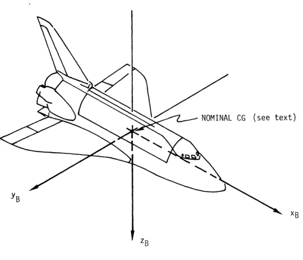
2-2 gives the vehicle mass properties during entry, appropriate to these two payload conditions. It should be noted that these data are referred to the "fabrication" frame definedby Figure 2-1; also illustrated is the
conventional "body-axis" frame used in dynamics analysis, so as to avoid the confusion which inevitably results in a discussion of mass
properties. The two frames are simply related by a translation from
the datum point of the fabrication frame to the vehicle center-of-gravity,
0o
and a 180 rotation about the y-axis.
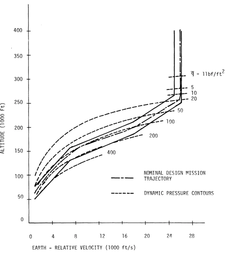
The entry flight envelope, a "corridor" in the altitude-velocity plane, is shownin Figure 2-2, along with a nominal design mission trajectory. The extremely large range of nominal dynamic pressures
Fundamental Geometric Properties
Property
Overall length Reference length Reference area WingspanMean aerodynamic chord
Table 2-2: Mass Properties
Property
Symbol No Payload 25K Payload(nominal) Dimension Weight CG location Moment of Inertia Product of Inertia Note: m CG YCG ZCG I xx I YY I zz I xy I Ixz Iyz 156, 617 1106.4 o.o2 373. 0 0. 779 5. 474 5.695 o.03 0.160 O. 001 1 81, 61 7 1083.5 0.02 376.7 0.805 5.849 6.067 0.1 40 0.001 pounds inches 'I 1 06 slug-ft 2 It I! TT II
1. Referred to fabrication frame of figure 2-1 2. Nominal value; tolerance m 2.0 inches
3. Nominal value; tolerance 1 3 x 1 03 slug-ft 2
Symbol S b c Value 125 ft 110.7 ft 2690 ft2 78.1 ft 39.6 ft Table 2-1:
H
>C- I-r) IA
0 a: mI >-cr--1zr LUJ H -I! I I~- >-4 :: +
z
C--J V3 X L >c uj < : I CC >- coO2 a; E -oE a) U-m C) 0 co C-E co a) 4Ja) a) a) S-., C-, -0 UL-/ / - /0 / I a) 5-0) .-Ll \ \\C0\
zi o__ --41, 4-1 I0 1. 4 = 11bf/ft 2 5 10 20 ISSION CONTOURS I I I I 4 8 1 6 20 24 28
EARTH - RELATIVE VELOCITY (1000 ft/s)
Figure 2-2. Entry Flight Envelope.
400 350 300 4i U- I- c-C) t-- _,-n:1 250 200 150 100 0 0 J 1 I !
(- q) encountered during the entry is indicated by the contours shown on the figure, and serves to emp)hasize the necessity for flexibility in any control system oierating ill this regime.
In order to attain the type of vehicle performance indicated by this envelope, a set of ground rules was developed for the aerodynamic
specifications; these are given in Table 2-3, repeated from Reference 2. Three points should be noted. First, the angle-of-attack range is un-specified for the transonic to high supersonic regime, although the
pitch trim limits described below place effective operational limits on
the angle-of-attack envelope in this regime. Second, as noted above, the longitudinal displacement of the center-of-gravity can range up to 2% of the reference length; the implications of this become quite clear when it is recognized that Reference 2 is, in essence, two aerodynamic data books, one associated with each center-of-gravity extreme. Finally, as will become evident by the discussion given in Chapter 4, the specifi-cation on the lateral hypersonic value for the coefficient Cn implies
that the uncontrolled airframe may be laterally unstable: i.e.,
diver-gent instead of simply undamped. Fortunately, in this case, the design
specifications are exceeded with sufficient margin to ensure basic stability (see Section 4.4.2).
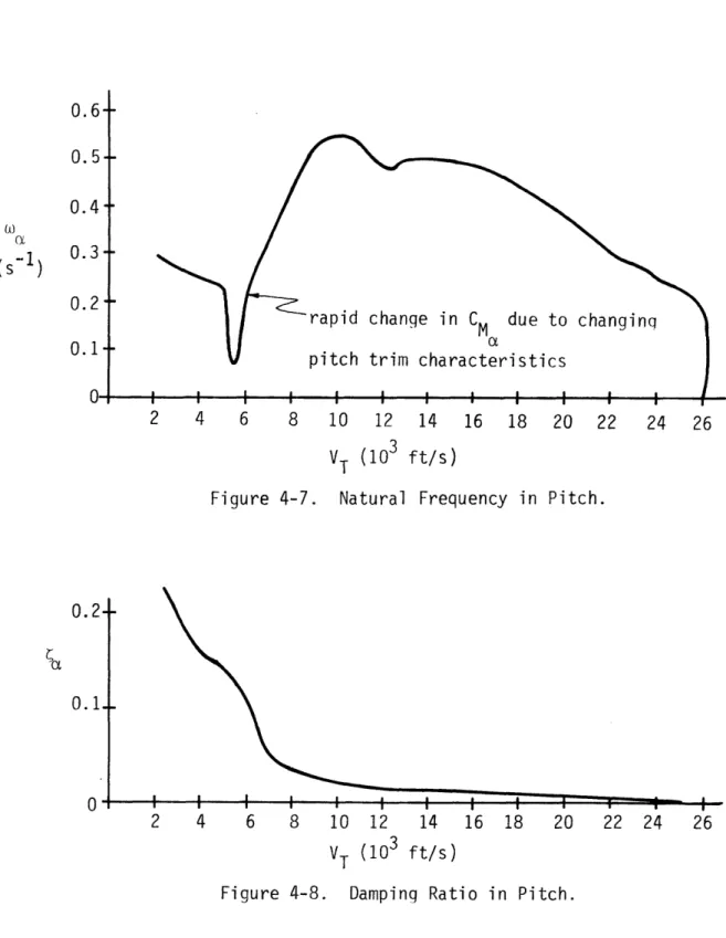
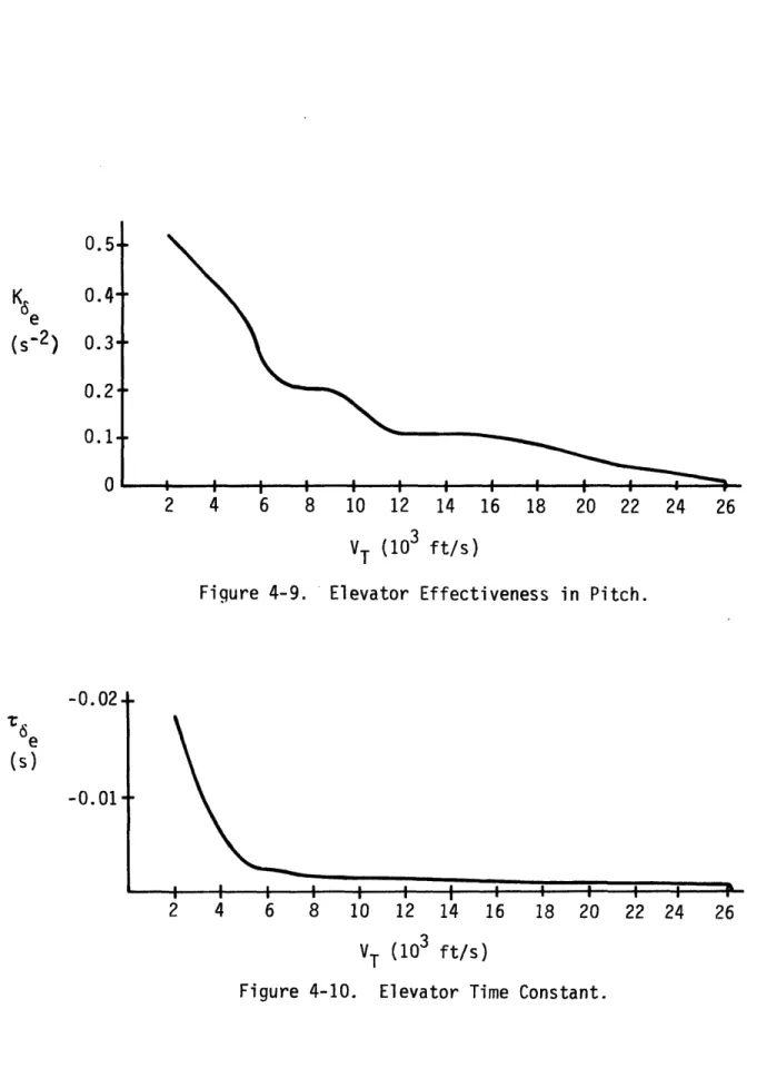
To gain some idea of the operational constraints in entry trajectory design, Figure 2-3 shows the longitudinal trim control "power" limits of the vehicle, due to fixed elevon deflection limits (see below), center-of-gravity displacement, and changing aerodynamics due to Mach number
and angle-of-attack variations. Considerably more constraints are im-posed by guidance considerations (e.g., targeting, heating, g-loads, etc.)
so that the "velocity/alpha" envelope rapidly narrows. Figure 2-4 shows an operational envelope, repeated from Reference 18, which provides an adequate margin about the nominal entry profile shown to ensure suf-ficient maneuverability in response to off-nominal guidance commands. Although this type of envelope is appropriate to the specification of con-trol design dependence on the vehicle's aerodynamic properties, a more pertinent flight envelope is used extensively in later chapters: the
"Mach number/alpha" envelope. Although this latter envelope is similar
Table 2-3: Design Ground Rules, 1 50K Lightweight Orbiter
Parameter
Value Angle of Attack Hypersonic Transonic Subsonic 25 deg to 40 deg 0 deg to 15 deg -5 deg to 20 degCenter of Gravity Range
Maximum Travel
Design Range Landing Performance
Payload
Landing Weight (with payload)
Minimum Design Touchdown Speed, VD
Longitudinal Stability
Minimum Hypersonic Static Margin Minimum Subsonic Static Margin
(AFT Center of Gravity)
2 percent body length
0.66 B- 0.68 B 25, 000 pounds 1 79, 000 pounds 1 65 knots Positive -2 percent B Lateral -Directional Hypersonic a = 34 deg Stability Directional Lateral Dynamic Subsonic a = 13 deg Directional Lateral -Cnp C, C''n Cn C 0D~ > -0. 001 > -0. 001 2 -0.002 > 0.001
-0 .001
I- 0 CM 0 CD 1~~-1 co (/) ra 0O L" E m-' I-Z U -r - ,-4 C c) -)ro CM o~~ · S.--'O~~ c3 0c
6~~
CC o, a CN 1 Cul :C F F 2 I IC LU 1 X ' 0 x-j
C)0 C-D CD LLJ LL OLfI.
w Cf O- * - NOMINAL DESIGN MISSION TRAJECTORY I I I I __ L I I I I I I I II I I I I 4 8 I l 12 I I I I I I -20 16 24 EARTH-RELATIVE VELOCITY Figure 2-4. (1000 ft/s) Angle-of-Attack Envelope. 40 co a) -! :cc - I-L_ C) In w -: 30-20 10 0 0 28 _ _· · Io
Du1-earth-relative velocity allows for a more complete specification of the
vehicle's aerodynamic prroperties, since Mlach n1umbe(r and
mangle-of-attack (leterrmine all of the trim aerodynamic characteristics of Ihe
vehicle.
No attempt will be made here to discuss the detailed characteristics of the bare airframe aerodynamic coefficients, since it is shown
inChap-ter 4 that a considerably more appropriate coefficient set exists which
better defines the vehicle dynamics. In fact, it is shown there how mis-leading a conventional interpretation of coefficient values can be; thus,
a discussion of these parameters is delayed until a proper background is prepared.
2.2 Sources of Control Authority
This section describes the basic characteristics of the two sources of torque authority available for attitude control during entry: the
reac-tion jet ACPS (Attitude Control Propulsion System) and the somewhat conventional surface controls, or the ACSS (Aerodynamic Control Surface System).
2.2.1 ACPS
The ACPS consists of 40 appropriately clustered bipropellant
thrusters*, each with a thrust of approximately 1000 lbf and a specific
impulse of 230 seconds, implying a mass flow rate of approximately
4.34 lbm/sec. At present, the usable minimum impulse time is
esti-mated to be 20 milliseconds, but as will be seen in Chapter 5, this figure will prove to be a small fraction of the total jet "on-time'" for a typical thrust pulse commanded by the control logic; this minimum impulse thus
has little impact on the controller design. Sixteen of the thrusters are located behind protective doors near the nose of the vehicle, and, be-cause of heating considerations, are unavailable during the entry. The remaining 24 jets are located in two symmetric tail pods, with no re-strictions on operation (see below for a possible exception). All 40 jets can be grouped into 16 "clusters" of co-linearly firing jets; the cluster
* Additional low thrust ( 25 lbf) "vernier't jets are available for on-orbit
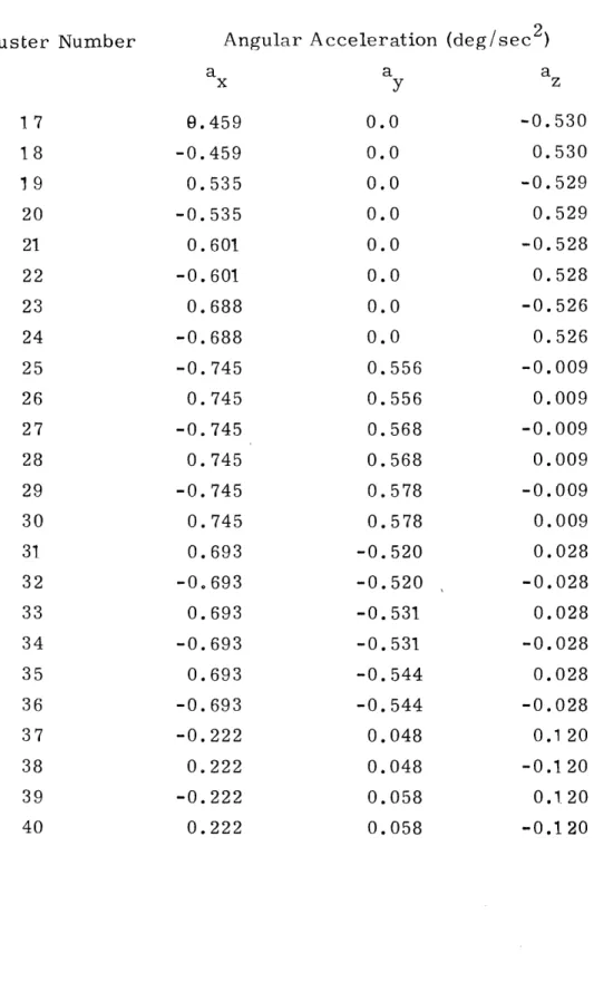
locations are shown in Figure 2-5, and the thruster identification num-ber assigned with each cluster numnum-ber is given in Table 2-4. Because of the significant displacement of the thrusters from the vehicle center-of-gravity, and because of the non-colinearity of thrust vectors with body-axes, there is a considerable amount of cross-coupling of torques produced by the jets. Shown in Table 2-5 are the angular accelerations (i.e., torque divided by appropriate moment of inertia) associated with
the firing of each jet in the tail pods, for the "forward" center-of-gravity
configuration. It should be clear from the data that there exists no thruster whose torque can be said to be essentially about a single body axis, so that it is somewhat misleading to refer to a jet as a pitch, roll, or yaw jet. However, when taken in particular combinations which mini-mize cross-coupling, it is often appropriate and convenient to use such nomenclature; this will be done occasionally in later chapters, to con-vey the sense of the basic torque being applied.
Control-axis coupling is not the only objectionable feature of the
ACPS; recent studies (see, for example, Reference 22) indicate strong
and unexpected coupling due to plume interference with the vehicle's flow patterns, noticeable at sufficiently high dynamic pressures. The net result (dependent, of course, on the particular thruster being con-sidered) is a flight-condition dependent deviation in vehicle response from what is encountered in exo-atmospheric operation. Thus, although it is convenient to view the ACPS as capable of providing idealized
torques essentially independent of the flight condition, some caution must be used in a generalization covering the entire entry. In fact, this
interference effect may very well preclude jet operation during certain
portions of the flight envelope. 2.2.2 ACSS
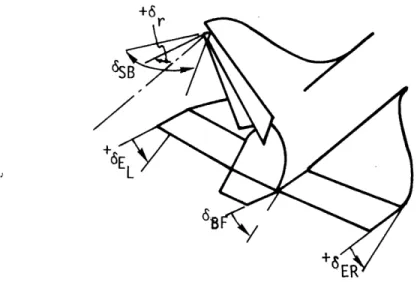
The set of control surfaces comprising the ACSS consists of left and right elevons, a conventional rudder, a programmed speedbrake, and a trim set body flap. These are illustrated in Figure 2-6 along with a table showing the effects of positive" deflections of these surfaces. The "derived" deflections of elevator and aileron are based on the fact that the elevons can be operated in tandem to emulate an elevator in its
r-X .2 ' E ._ E >- _ - m M L l a, --- *CU1 3. Q) ._ ., · 0O+- (1) a,. ._ ( * Ur Cm 0 - S.-a) (n :3 CD, r)O s-CMa) (.-I . c-LO r--4I a) ._
! a
= CL ! IIX
1= ._ C O-4 .'A X = f", 4- 0 C',,i cr, -- 4 1Table 2-4: Thruster Cluster Allocations Cluster Location 1 2*:-, 3 , 4* 56 * 6t 7 8 9 10 1l 12 1 3* 1 4* 15 16 Number of 2 2 2 2 2 2 4 4 3 3 3 3 2 2 2 2
Thrusters
Thruster Number10, 12 14, 16 13, 15 9, 1.1 6, 8 5, 7 17, 19, 21, 23 18, 20, 22, 24 32, 34, 36 26, 28, 30 25, 27, 29 31, 33, 35 2, 4 1, 3 38, 40 37, 39
Table 2-5: Angular Accelerations o Tail Pod Thrusters
(about body rame axes)
Thruster Number a 17 18 19 20 21 22 23 24 25 26 27 28 29 30 31 32 33 34 35 36 37 38 39 40 9 . -0. O. -0. . -0. O. -0. -0. O. -0. O. -0. O. O. -0. O. -0. O. -0. -0. 0. -0. O. Angular Acceleration a 459 459 535 535 601 601 688 688 745 745 745 745 745 745 693 693 693 693 693 693 222 222 222 222 y 0.0 0.0 0.0 0.0 0.0 0.0 0.0 0.0 0.556 0.556 0.568 0.568 0.578 0.578 -0. 520 -0.520 -0. 531 -0. 531 -0. 544 -0. 544 0.048 0.048 0.058 0.058 (deg/sec 2 ) a z -0.530 0.530 -0.529 0.529 -0.528 0.528 -0.526 0.526 -0.009 0.009 -0.009 0.009 -0.009 0.009 0.028 -0.028 0.028 -0.028 0.028 -0.028 0.120 -0.120 0.120 -0.120 29 x
+6
Figure 2-6. Control Surface Conventions.
*Note: Fictitious surfaces defined by: de - ½(6EL + ER)
da - (6EL - 6ER)
**Note: Unfamiliar symbols are defined in chapter 4. PRIMARY
SURFACE POSITIVE VEHICLE PRIMARY FORCES NAME DEFLECTION OF RESPONSE** AND MOMENTS**
Left Elevon 6EL+ +C
EL Right Elevon 6ER -- Cq Rudder r +C, -n Speedbrake 6SB Vx +CD Body Flap 6BF - -CM Elevator* 6e -0 -a -CM Aileron* 6a + +C
pitch torque capability, and operated differentially to emulate ailerons in roll torque capability. The rudder is actually incorporated with the speedbrake, but independent operation of the two is provided for.
Both the speedbrake and the body flap are surfaces auxiliary to the essential control functions of the ACSS. Specifically, the
speed-brake, a vertical controllable flare surface of the dorsal fin, has a
pre-programmed deflection schedule through the entry (see Figure 2-7; taken from Reference 2), so as to enhance lateral stability. With slow deflection rates, it may thus be viewed as a weak augmenter of the un-controlled airframe dynamics, as opposed to a control surface available
for transient torque applications. Similarly, the body flap, a ventral
horizontal trim surface, is set to a fixed deflection depending on the
fore-aft displacement of the center of gravity from its nominal forward
location (see Figure 2-7). In this manner, the body flap generates a pitch trim torque, so that the trim elevator deflection in the presence of
an "aft'" center of gravity approximates the trim setting for the nominal
forward location (see Reference 2). The point to be recognized is that, as with the speedbrake, the body flap is constrained to low deflection rates and is thus not available for transient attitude control. Thus, both surfaces may be neglected for dynamics analysis by incorporating their
static effectiveness into the bare airframe characteristics; this is done
in the analysis of the following chapters.
The deflection and deflection rate limits of the elevons and rudder are given in Table 2-5. The mechanical arrangement of the hardware (actuators and surfaces) provides the primary specification on the deflec-tion limits, although, as noted in the table, undesirable heating charac-teristics may impose further restrictions in range. It should be noted
Table 2-5: Surface Deflection and Rate Limits... . . ..
Effectnr Deflection Limits Deflection Rate Limits
(deg) (deg /sec)
8M~EL ~-40, +15(+10*) +15 E L 8HER -40, +15(+10*) ±15 8r + 28 ±15 de -40, +1 5 -6a +±15
-
I
I
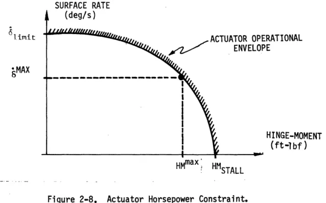
'l l l -Q( t 0l I I I as 'a a) V)(/3U, ro LLTo a) V CM a; ,-LL.-n3 0 C33 :3 _L-(\J. 0X t C) Od 00 CM ,_ I I 1-0) I U- a) co0 -Co. -3 Ii CDthat constraints due to heating are still poorly defined, so that the specification of deflection limits is an open issue. Determination of maximum rate limits is more difficult, and perhaps even misleading due to the nature of the limit. Shown in Figure 2-8 is an idealized plot
of surface rate versus hinge-moment, the latter variable being the
torque applied about the surface hinge due to aerodynamic forces acting on the deflected surface. The curve itself is determined by actuator
torque and horsepower sizing, so that zero rate capability is associated
with a stall hinge-moment, while the no-load condition is associated with
a large rate limit. This would be sufficiently complicated as it stands;
however, the hinge moment itself is a function of dynamic pressure, Mach number, trim angle-of-attack, and surface deflection magnitude.
SURFACE RATE -RATIONAL )E HINGE-MOMENT (ft-lbf) HMmax HMSTALL
Figure 2-8. Actuator Horsepower Constraint.
The conventional solution to this problem is to estimate a maximum anticipated hinge-moment in the regime of interest, and then find the
associated maximum rate from the appropriate actuator data. Because
of the lack of readily available actuator data, this approach was not taken in specifying the values given in the table; they are, instead, conservative values agreed upon by several workers in the field to be fairly accurate first estimates which will suffice until better actuator modelling becomes
limit
available. Whatever the values, however, it must be remembered that
they are, in actuality, not fixed, but instead, variable rate limits de-pendent on several factors.
Also listed in the table are the "elevator" and "aileron" deflection
limits, used for control system design and evaluation. It should be clear from the values given in the table and the transformation equations given
in Figure 2-6, that the elevator and aileron limits are inconsistent with
the elevon limits. For example, an elevator deflection of + 5 degrees (down) implies that both left and right elevons must be at their 1 5-degree limits, in turn implying no capability for differential deflections which will maintain the desired elevator deflection. Thus, a 1 5-degree elevator
deflection limit is incompatible with any non-zero aileron limit. This
discussion is continued in more detail in Section 5.4.2.I,; covering
con-trol system output processing; for now, however, the inconsistent limit set provides a useful approximation to the actual situation. The rate limit situation is similar; however, in later chapters it will be seen unnecessary to the synthesis effort to specify elevator and aileron rate
limits, so that no values are given in the table.
The complete specification of the aerodynamic surface coefficients,
used in determining control torques generated by surface deflections,
is given in Reference 2; no attempt is made here to repeat this volumin-ous data. It is, however, appropriate to condense some of this informa-tion in a format which helps to better visualize the approximate surface control authority which can be expected during a "nominal" entry. A first approximation to surface effectiveness in producing body-axis
torques is obtained by assuming that the elevator is exclusively responsible for pitch torques, the aileron for roll, and the rudder
for yaw. That this is not true is seen by the non-zero cross-control effectiveness coefficients of Reference 2; however, for this discussion, a simplified view is adequate, so that the control accelerations about the body axes are given as follows:
a
qSb Ct6 Ha; ay=qSc =qSb
a = qa c a -C 8 (2-1)
x t, 8 .8 y m e z n8 r
where the mass and geometric properties have been introduced above, and where the aerodynamic surface control coefficients are specified functions of Mach number and trim angle-of-attack. If the trajectory parameters are defined by Figures 2-2 and 2-4, then the ACSS control acceleration effectiveness may be plotted versus velocity by use of (2-1), as shown in Figure 2-9. It should be noted that the normalization used
2
implies, for example, a roll acceleration capability of axdeg/sec
per degree deflection of the aileron.
The obvious influence of low dynamic pressure at the beginning of entry is apparent from the figure. Some of the later modulation in effectiveness is due to dynamic pressure changes; the remainder is due to changes in the aerodynamic coefficients due, in turn, to Mach
number and angle-of-attack changes. Perhaps most striking is the very late effectiveness of the rudder; this is due to the "shadow" effect
at the relatively high angles-of-attack maintained throughout most of
the entry. The implications for control design are discussed in a later
section. To gain some appreciation of the acceleration magnitudes, it is instructive to compare the histories of Figure 2-9 with the ACPS
acceleration levels of Table 2-5. For example, a positive pitch
accelera-tion of approximately 1.1 deg/sec2 can be obtained by firing thrusters
25 and 26; in the middle of the entry, a few degrees of elevator can
completely cancel this. A similar situation exists for ACPS and aileron
induced roll accelerations. Yaw, of course, is not controllable by the rudder until late into the entry, so that a single "yaw" ACPS thruster (e.g., number 1 7) provides a much higher acceleration level than the
rudder, for the majority of the entry. Further discussions comparing
ACPS to ACSS control are found in Section 2.5.
2.3 Performance Requirements
As noted earlier, the basic objective of the entry control system is to provide direct control over angle-of-attack and bank angle, in response to guidance system attitude commands, utilizing the ACPS and ACSS within their design constraints. Attitude hold accuracy and
5 10 15 20 25 30
5 10 15 20
RELATIVE VELOCITY
25 30
(103ft/s)
SINGLE YAW JET ACCELERATION LEVELs0.5 deg/s2 (Jets 17 through 24) 5 10 15 20 RELATIVE VELOCITY (103ft/s) 2.5 2.0 1.5 1.0 ax 6a (S-2 ) 0.5 -0.5 a 6 e (s-2) -0.4 -0.3 -0.2 -0.1 -0.25 -0.20 az Sr (s-2 ) -0.15 -0.1 0 -0.05
system requirements, but all other performance specifications not directly associated with subsystem constraints are of secondary
im-portance. In particular, attempting to apply to this problem conven-tional handling quality specifications (such as those found in References
12 and 18) may lead to the imposition of design constraints superfluous to the mission, whose satisfaction may require increased demands on the controller subsystems and/or degradation of the primary functions
of the control system. This is not to suggest that no attempt should be
made to satisfy secondary performance requirements; on the contrary,
when they can be satisfied in the normal course of the controller design effort it is clearly advantageous to broaden the scope of the system's
performance objectives.
The primary performance requirements should specify attitude
hold and maneuver characteristics necessary for successful operation
with the guidance system. Unfortunately, few guidance studies have
con-centrated on specifying the required control system performance, and
the data that is available is of an informal nature with the expected num-ber of qualifying conditions. From a general consensus, it would appear that a steady-state attitude hold accuracy of approximately 1 degree in
angle-of-attack and 3 degrees in bank will satisfy the guidance require-ments. Maneuver rates are even less specific, but the indications of Reference 13 imply a bank rate capability in excess of 5 deg/sec in response to a bank reversal occurring at high dynamic pressures. No specific minimum values for angle-of-attack rate have been found in the literature; discussions with workers in the field suggest very low levels, below those which naturally occur in the process of control loop stabiliza-tion of the longitudinal dynamics. In this discussion of vehicle attitude specifications, it is appropriate to note that there is, at present, some
concern over sideslip induced heating rates, so that an airframe opera-tional constraint may limit sideslip excursions to less than some
maximum value. Present indications set this value at 5 degrees; again, it will be seen that maintenance of vehicle stability (in the lateral axes)
results in sideslip excursions considerably smaller than this specifica-tion. This rather informal discussion is summarized in Table 2-6; the
Table 2-6: Attitude Control Performance Requirements
Steady-State Error Maneuver Rate
The performance requirements imposed by the effector subsystem constraints follow fairly directly from the ACPS and ACSS operational characteristics described in the previous section. Specifically, it is clear that an implicit performance requirement on the controller is low
ACPS fuel expenditure so as to stay within an allocated entry budget, presently 700 pounds. Additionally, two other ACPS subsystem oriented requirements may be noted. First, because of the undesirability of high thruster pulse rates, the ACPS torque commands, issued by the control
logic, should be at a low frequency, specifically ruling out any attempt at pulse rate modulation. Second, because of the present concern with thruster firings at high dynamic pressures (see Reference 22) an implied
requirement on the controller is the minimization of ACPS use in those flight regimes. In a similar fashion, the actuator horsepower and torque characteristics, combined with skin heat rates, limit surface deflections and rates. Thus, the ACSS imposed constraints imply small deflections at low rates. These performance requirements imposed by both ACPS
and ACSS constraints and desired operational modes are necessarily
qualitative, due to a lack of available data; they must be recognized, however, in any design effort.
2.4 Off-Nominal Considerations
Early attention in a design effort to off-nominal situations is a
prerequisite for successful control system operation in a realistic en-vironment. To this end, this section discusses some of the more
ob-vious considerations which are arbitrarily labelled "off-nominal", to distinguish them from the somewhat idealized "nominal" vehicle and
trajectory characteristics commonly used for design synthesis. It
should be noted that the definition of the "nominal" parameters defining the control problem (e.g., vehicle aerodynamic coefficients, guided altitude/velocity profile, etc.) is a difficult enough task, let alone the specification of deviations from nominal. Thus, many of the
considera-tions here are qualitative, pending further study and assignment of numerical values specifying ranges of variations on parameter values.
The type of considerations directly affecting control system design can be grouped into two categories: those to do with modelling accuracy and vehicle parameter definition, and those associated with subsystem
"errors." Both categories are discussed below. A third area which
could be considered is associated with the large entry flight envelope; thus, a trajectory within the envelope which is not the "nominal"
traj-ectory (see Figures 2-2 and 2-4) could be considered "off-nominal". Recognizing the fact that the envelope itself is "nominal", the discussion becomes one of more semantics than engineering. The approach taken here is to simply delay this flight envelope discussion to the next section,
and discuss its implications there.
2.4.1 Model Accuracy
As will be seen in Chapters 4 and 5, control law synthesis is dependent on the definition of a simplified vehicle model to account for the more fundamental inertial and aerodynamic properties of the
vehicle. A dependence on the knowledge of both the aerodynamic
co-efficients and the mass properties is implicit in this modelling effort, and in fact, in any practical control design effort.
As noted earlier, the "nominal" aerodynamic coefficient values are given in Reference 2; given in Reference 1 is a table describing tolerances and variations of the coefficients appropriate to a slightly different vehicle from the design base vehicle of Reference 2.
Assuming that these values are an appropriate indication of the spread to be anticipated in the coefficient values for the vehicle described above, the data from Reference 1 may be summarized as shown in Table 2-7. As may be noted, the table only gives values at two Mach number/
Table 2-7: Possible Aerodynamic Coefficient Variations
Coefficient Lift Coefficient, CL
Pitching Moment Coefficient, CM
Pitching Moment Slope, M
aCN
Drag Coefficient, CD
Lift-to-Drag Ratio, L
D
Side Force Slope, Cy,
Yawing Moment Slope, Cn
Rolling Moment Slope, Ct
Yaw Moment due to Aileron, Cn
Mach No. Angle acf Tolerance Attack Variation
2 15° 10 30° 2 15° 10 30° 2 15° 10 30° 2 1 5° 10 30° 2 15° 10 30° 2 1 5° 10 30° 2 15° 10 30° 2 15° 10 30° 2 1 5° 10 300 % Increment 3% 8 +±0.04 13 ±0.08 10% 25 +0.012 25 +0.002 3% 7 +0. 003 3 +0.001 3% 1 7 +0.04 10 ±0.04 6% 6 +0.13 6 +0.07 10% 20 ±0.003 20 ±0.001 1 0% 25 +0.0004 25 +0.0006 10% 50 +0.0006 17 ±0.0003 10% 30 ±0.0001 !'0 ±0.0001 Aileron Effectiveness, C ,
Rudder Side Force, Cy 8
r 2 150 10% 20 ±+0.0002 10 30° 20 +0.0002 2 15° 5% 10 +0.0001 10 30° * * Rudder Effectiveness, Cn
Roll Moment due to Rudder, Ct
2 1 5 10 30° 2 1 5° 6r 1 0 30° 5% 10 +0.00006 5% 1 0 +0. 00004 * *
angle-of-attack pairs, so that it is a fairly sparse data set. The last column, which gives the variation, indicates the anticipated
maxi-rl U) dile renc(e i)btween the p (rese(rt (lata book values ad the data 1)ook
values associated with the final froze(n configuration; this type of varia-tion is due to design changes and/or Improved wind tunnel data. It should
be noted that both a percentage variation and an accuracy band is given;
this latter is given in units of per degree where appropriate, in contrast
to the per radian usage later in the text. The column describing the tolerance is associated with the uncertainty in knowledge of the
coeffi-cient; as such, it is a tolerance about the value obtained after the
varia-tion of the last column is taken into account.
Two points should be made regarding the data of this table. First, several workers in the field hold that these data are optimistic and that the actual variations encountered may considerably exceed the values
given. Unfortunately, placing an uncertainty level on the coefficient variation levels appears to be beyond the scope of present aerodynamic design techniques. The second point is that, even in the face of these "optimistic" values, some of the variations are quite large. As will be
seen in Chapter 4, the basic airframe dynamics are specified by CMo ,
Cn , and Ct , which are particularly subject to large variations, as
shown in the table. It is also appropriate to note the relatively large possible variation in the adverse aileron coefficient Cna,, a point which has caused considerable confusion in the entry control design area. The
details of this discussion are delayed until Chapter 7, after the control
system has been described, so as to better explain the source of this confusion in terms of vehicle dynamics and control loop characteristics.
The other aspect of vehicle modelling accuracy is conerned with
the specification of the vehicle's mass and inertia characteristics. As seen in Table 2-2, there are two basic sets of mass properties,
depend-ent on the weight of the payload. The major effect of such a mass varia-tion is to change the center-of-gravity locavaria-tion in the axial direcvaria-tion (i.e., along XB), which, as may be inferred from the data of Reference
2, changes the trim attitude of the vehicle for a given elevator trim setting. As discussed earlier, the body flap may be used to compensate
for these payload induced trim variations, simply by following an open loop deflection schedule which allows the appropriate trim moment to be applied. Thus, as will be seen in the development to follow, it is convenient to label the 25, 000 pound payload/forward CG situation as "nominal", with the no payload/aft CG situation as an off-nominal, small deviation case, with the basic correction being provided for by the body flap.
Of perhaps more importance to the control problem are lateral
displacements of the center-of-gravity, which, as shown in Table 2-2, destroy the vehicle's longitudinal plane of symmetry. The two-inch y-axis tolerance shown in the table can be considered as an unknown variation from the nominal geometric plane of symmetry. The effect of such a displacement, as discussed in Section 5. 2. 2, is to produce a disturbance torque primarily about the body roll axis, which, if uncom-pensated for, will lead to a divergent bank attitude. As discussed in
this section, this imposes a requirement for a lateral trim logic to
main-tain attitude in the presence of disturbance torques whose values cannot
be precisely predicted.
2.4.2 Subsystem Errors
The subsystems which directly affect control system performance
are the input subsystems, which provide vehicle state information, and the output subsystems, which translate control system commands into
attitude controlling torques.
The vehicle state information can be categorized into two groups:
attitude information and trajectory parameter information. At present,
the techniques for providing either type are not well-defined, and thus,
it is a difficult task to estimate the performance level of the sensor/ estimator subsystems which will eventually be required. Furthermore,
control system design work has not matured sufficiently to place well-founded specifications on the accuracy of the input variables, although this is an area of current design effort. Some work has been done,
Chapter 4 for a complete definition) from processed inertially derived
information, and is reported on in References 14 and 24. The former
describes estimates of angle-of-attack and sideslip and describes error
growth down the trajectory, implying a requirement for additional sensor information during the latter portion of the entry. The latter
reference describes angle-of-attack and sideslip estimation, along with
bank attitude estimation. Wind and no wind cases are considered; in
addition, the incorporation of a lateral accelerometer measurement in
the sideslip estimate is described. The findings show that -sigma
errors on the order of a few tenths of a degree can be expected
(specif-ically, a O.2 deg, R ' 0.2 deg, and < 0.4 deg, for no
un-modelled winds). The presence of unknown winds will naturally degrade
the accuracy of the inertially derived information, and is discussed further in the reference. As noted above, current effort is directed
towards a better definition of both practical estimator performance and
anticipated control system requirements.
The second category of state information is trajectory oriented;
i.e., Mach number, dynamic pressure, etc. Very little work has been
done in this area, and accuracy estimates are very difficult to obtain. Needless to say, trajectory state estimation will require a concerted
effort over the next few months of the design period. Similarly, control
system accuracy requirements have not been determined, al:hough some indications of vehicle sensitivity have been determined from simulator
studies. These are reported on in Section 7.3.4.
Output subsystem errors can be categorized into those associated
with the ACPS and those associated with the ACSS. With the former
subsystem, the basic uncertainties involved are those of thruster
loca-tion, thrust level, and pulse timing. As is seen in Chapters 4 and 5,
the control law developed here is effectively insulated from these
un-certainties by the use of a jet selection logic, to translate control sys-tem commands into individual thruster firings. Thus, most of the errors peculiar to the ACPS should have little effect on controller performance, assuming the jet selection logic provides adequate compensation to deal with off-nominal situations. It should be recognized, however, that the
oft-discussed design specification of near nominal operation with two jets failed (off) can be a severe constraint, depending on the particular jets failed. For example, it may be seen from Tables 2-4 and 2-5 that a two-jet failure in cluster 7 implies a maximum yaw acceleration
capability of less than 1 .1 /sec2; clearly, a demand by the control law
for a larger acceleration level will be unsatisfiable by the jet select
logic.
With the ACSS, the basic uncertainties involved are those of
deflection attitude accuracies. Low frequency errors (e.g., static
off-sets) will show up as mistrim torques, so that closed-loop control sys-tem operation will provide the proper compensation for this type of error. High frequency errors have not been investigated, and their effect on control system operation has, to date, not been examined. Clearly, this is an area for additional work and subsequent subsystem
performance specification.
2.5 Implications for Control System Design
Even with the cursory vehicle description and performance
re-quirement specifications given above, certain basic control system
design issues can be readily identified; it is the purpose of this section to briefly describe some of these issues by way of commenting on the
descriptive material just presented.
Perhaps the most unique characteristic of this design problem is the large range of vehicle/environment parameters encountered during the entry, due to both the large nominal flight envelope (as illustrated in
Figures 2-2 and 2-4) and the large number of possible off-nominal situa-tions which can be encountered. This range in the problem "parameter
space" must, of necessity, strongly influence the design effort. One of the questions which must be answered concerns the appropriate utilization
of both the ACPS and the ACSS in the face of order-of-magnitude changes
in dynamic pressure. Clearly, the ACPS must be used early in the
entry. From the surface effectiveness histories of Figure 2-9, full
entry. The area of concern, of course, is in between these extremes.
The type of design trade involved is somewhat more obvious if the
longitudinal and lateral aspects o the attitude control problem are
treated separately, as is done more formally in Chapters 4 and 5. Thus,
from the elevator effectiveness history of Figure 2-9, it appears feasible
to use the elevator relatively early, and maintain its use down the entry, since a few degrees of elevator deflection provide a control acceleration level comparable to a "pitch" jet firing (e.g., thrusters 25 and 26 shown in Table 2-5). Also supporting early elevator utilization is the desire to minimize ACPS fuel expenditures, the possible unpredictability of thrust-er effectiveness at high dynamic pressures, and the difficulty of ACPS control law design synthesis at "significant" dynamic pressure levels (see below). On the other hand, early (and, in fact, during any part of the entry) utilization of the elevator may be constrained by actuator
hinge-moment/horsepower requirements, skin surface heating rates, and
uncertainty in control authority due to both the large Mach/alpha envelope and the significant possible variations in the surface effectiveness
co-efficient. Clearly, any finalized pitch ACPS/elevator control law must
functionally express the design compromise which satisfies both the ACPS and ACSS constraints and the performance specifications placed on the controller.
The lateral control problem involves the same trades, but is com-plicated by the lack of rudder effectiveness through the majority of the
entry. Delaying the use of the aileron until conventional control (i.e.,
aileron controls roll, rudder controls yaw) is possible is one approach; this of course implies that the aileron authority throughout most of the
entry (see Figure 2-9) is not taken advantage of, and, in turn, implies
greater ACPS activity with its concommitant possible problems. A more reasonable alternative is to use the aileron during early entry for body-axis roll control, eliminating the requirement for the ACPS to provide roll torques, "yaw" ACPS firings still being required for ZB
-axis control. This has the distinct advantage of emulating conventional
operation, where the rudder authority is replaced by yaw jet firings;