Drive Train Improvements and Performance Evaluation of a Robotically
Steered Needle
by
Carmen Marten-Ellis Graves
SUBMITTED TO THE DEPARTMENT OF MECHANICAL ENGINEERING IN
PARTIAL FULFILLMENT OF THE REQUIREMENTS FOR THE DEGREE OF
BACHELOR OF SCIENCE
AT THE
MASSACHUSETTS INSTITUTE OF TECHNOLOGY
JUNE 2011
02011 Carmen Marten-Ellis Graves. All rights reserved.
The author hereby grants to MIT permission to reproduce and to distribute publicly paper and electronic copies of this thesis document in whole or in
part in any medium now known or hereafter created.
ARCHIVES
MASSACHUSETTS INSTITUTE OF TECHNOLOGYOCT
A2011
~L3AR IES
Signature of Author:Department of Mechanical EngineedQ May 13,2011
Certified by:
Conor J. Walsh Instructor in Radiology, Harvard Medical School - r) Thesis Supervisor
Certified by:
Alexander H. Slocum Professor of Mechanical Engineering Faculty Supervisor Accepted by:
John H. Lienhard V essor of Mechanical Engineering Chairman, Undergraduate Thesis Committee
Drive Train Improvements and Performance Evaluation of a Robotically
Steered Needle
by
Carmen Marten-Ellis Graves
Submitted to the Department of Mechanical Engineering on May 13, 2011 in partial fulfillment of the Requirements for the Degree of Bachelor of Science in
Mechanical Engineering
Abstract
The focus of this thesis is on the design and evaluation of a robust drive mechanism intended to robotically steer a thermal ablation electrode. The device is intended to enable more efficient kidney tumor ablation therapy guided by CT scanning. The steering mechanism is based on the concept of substantially straightening a pre-curved Nitinol stylet by retracting it into a concentric outer cannula, and re-deploying it at a different position. A drive mechanism was previously designed to actuate the cannula and stylet motions. While successfully demonstrating the concept, the previous prototype used a screw-spline mechanism that had a key and groove that were difficult to manufacture, assemble and align. To address the issue of the key being misaligned with the spline nut, an alternative, more robust means was considered for
constraining the screw-spline from rotating. This was achieved through the design of a new profiled threaded shaft and nut that reduced the part count and simplified manufacturing and assembly. To determine the optimal parameters for the profile shape, an analytical expression was derived that related the tolerance between the nut and shaft to the angular backlash, which was validated using SolidWorks.
A deterministic design process was then followed to size the actuators and transmissions
for such drive mechanisms given a set of specifications for cannula/stylet force and speed. Specifically, the gear train was designed to ensure sufficient force for deploying a pre-curved needle from a cannula and into a gelatinous solid based on previously collected experimental data. Using this process, Faulhaber AM1524 micro-stepper motors with 15A planetary
gearheads were selected that could provide 10 N and 20N of force to both the cannula and stylet (in line with the screws) at a speed of 7 mm/s. Accuracy and repeatability of the drive
mechanism were measured in a bench-top experiment using calipers and a protractor and yielded sub-mm values for translation and approximately two degrees of play for rotation. Targeting experiments were also performed in ballistics gelatin and ex-vivo tissue samples where the distal tip of the stylet was recorded with a camera and CT scanner and demonstrated that the device is ready for testing with an integrated thermal ablation system.
Thesis Supervisor: Alexander H Slocum Title: Professor of Mechanical Engineering
Acknowledgements
I would like to thank Conor Walsh for all of his support throughout this project. This thesis
project has been an invaluable experience. Thanks to Jan Jouke Harms for all his help during the testing phase of the project. I would also like to thank Professor Slocum for providing the
opportunity for this experience, and Dr. Rajiv Gupta for his time, insight, and help using the CT scanner at MGH.
Special thanks to my parents, my brother Christopher, and Delmy for supporting me throughout my life in all of my endeavors. And thanks to Joshua Ramos for sticking by me through my time as an MIT undergraduate.
Table of Contents
Abstract ... 3 Acknowledgem ents... 5 Table of Contents...7 List of Figures ... 8 List of Tables ... 11 1 Introduction ... 132 Screw-spline Design and M odeling... 16
2.1 Initial Design Embodim ent ... 16
2.2 Screw-spline design... 18
2.3 M odeling ... 20
2.4 Detailed M echanism Design ... 22
3 Transm ission and Actuation Sizing ... 24
4 Prototype Construction and Control... 30
4.1 M anufacturing... 30
4.2 W iring and Control... 32
5 Bench-Top Evaluation... 34
5.1 Translational Accuracy and Repeatability ... 34
5.2 Angular Accuracy and Repeatability ... 38
6 Evaluation of Needle Steering in Ballistics Gellatin and Ex-vivo Tissue... 41
7 Conclusions and Future W ork ... 47
References ... 49
List of Figures
Figure 1.1 Percutaneous needle appropriately positioned in a tumor cell for RF ablation therapy. The needle provides a source of RF energy that heats and kills the cancer cells of the tu m o r... 14
Figure 2.1 Previous gear-train design (a) and spline and key interaction (b)... ... . . 16
Figure 2.2 With two motors meshed with the screw nut and the spline nut, cannula movement can be controlled to translate and rotate... 17
Figure 2.3 The drive system for the screw-spline. Two different cross-sections are shown in (a) an d (b )... 17
Figure 2.4 Cross-section of sample profiles for constraining shaft rotation (mating female "nut" not shown). The profile on the left is a tri-lobe shape and is typically used for high torque applications as it results in the minimum local stress concentrations. However, it requires high machining precision. The profile on the right is ideal for sliding applications, and can easily be m ade for m ass production. ... 18
Figure 2.5 Profiled rods and the root diameter of threads needed in order to reach the unthreaded center of the screw . ... 19
Figure 2.6 Male (blue) and female (red) profiles used for the screw (a) and the screw-spline (b).
... 19
Figure 2.7 The profiled screw (blue) and gear (red) shown aligned (left) and rotated (right)... 20 Figure 2.8 Maximum backlash between profiled nut and shaft as a function of contact length and different tolerance gaps calculated using a geometric model and SolidWorks. ... 21 Figure 2.9 New nut profile design (red) to ensure very little angular play with screw (blue). The
contact length is about 6.5 m m . ... 22 Figure 2.10 New gear-train design (a) and profile interaction (b)... 23
Figure 3.1 Power required to move the cannula as a function of velocity for varying desired force. Desired operating range is squared off in red... 25
Figure 3.2 Torque-speed curve and power-speed for Faulhaber AM1524 micro-stepper motor. The maximum power of the motor is about 1.6 W... 26
Figure 3.3 Torque-speed curve and power-speed for Faulhaber AM1524 micro-stepper motor and straight line approximations. At a speed of 8000 rpm and above, the torque speed curve can be approximated as the purple dashed line, while bellow 8000 rpm it can be approximated by the orange dashed line... 28
Figure 4.1 The fabricated parts: (a) screw-spline; (b) profiled top; (c) screw; (d) profiled nut; and (e) threaded screw -spline nut. ... 31
Figure 4.2 Fully assem bled prototype... 31
Figure 4.3 Control box consisting of USB stepper motor controller, power supply, and four stepper m otor drivers. ... 32
Figure 4.4 Motor connection to D-sub connector to control box. ... 33
Figure 5.1 The amount that the cannula translated when commanded was determined by
measuring the distance between the upper and lower supports of the robot with calipers as show n in the im age. ... 34
Figure 5.2 Measured axial translation of the cannula compared to the commanded values. The desired relationship is shown as the red line and has a slope of 1. The line of best fit, black, has a slope of 1.0018 ... 35
Figure 5.3 The amount that the stylet translated when commanded was determined by measuring the distance between the gear and the top of the screw with calipers as shown in the im ag e ... 3 6
Figure 5.4 Measured axial translation of the stylet compared to the commanded values. The desired relationship is shown as the red line and has a slope of 1. The line of best fit, black, has a slope of 1.0003... 37
Figure 5.5 Picture taken after a given command. The ruler is a stationary straight edge used as a reference to calculate the angle that the robot is at. A line parallel to the straight edge is drawn (red lines) at the center point of the protractor (yellow X), and the angle at which the robot's at with respect to the straight edge can be read from the image (blue square).
... 3 8
Figure 5.6 Measured angular displacement of the robot compared to the commanded values. The desired relationship is shown as the red line and has a slope of 1. The line of best fit, black, has a slope of 0.9962... 39
Figure 6.1 The robot is suspended by a rig allowing the needle to be inserted into various
Figure 6.2 Stylet of diameter 0.838 mm and bend of 10 mm radius deployed from cannula
perpendicular to view ing field ... 42
Figure 6.3 The image from Figure 6.2 with circle of diameter of 380 pixels and the conversion factor of 169 pixels in 10 mm. Therefore, the radius of curvature of the stylet is about 11
m m . ... 4 3
Figure 6.4 CT scanning test setup used to view stylet within the ex vivo tissue sample. ... 44 Figure 6.5 Slice of compilation of DICOM images showing the cross-section of the robot and
needle in which the radius of curvature of the needle is visible... 45 Figure 6.6 A circle drawn on the cross-sectional image of the stylet matching the radius of
List of Tables
Table 3.1 Parameters changed between first and second prototype. ... 29
Table 5.1 Averages and standard deviations for the measurements compared to the command values for cannula translation. ... 35
Table 5.2 Averages and standard deviations for the measurements compared to the command values for stylet translation ... 37
Table 5.3 Averages and standard deviations for the measurements compared to the command values for angular displacement... 39
Table 6.1 Radii of curvature of stylets tested. 0... ... .. .. ... . . 41
Table 6.2 Results of stylet radii in gel. ... 43
Table 6.3 Results of stylet radii of curvature in liver. ... 46
Table Al Axial cannula positioning data...58
Table A2 Axial styet positioning data... 59
1 Introduction
An increasing number of minimally invasive surgeries and procedures have begun to replace traditionally open surgeries and procedures since the last quarter of the 2 0th century. Not only
does minimally invasive surgery reduce the trauma to the patient by decreasing pain, risk of infection, and scarring, but it also greatly reduces the cost of the procedure for the hospital due to shorter hospital stays.
Similarly, robotics has begun to take a greater role in surgical applications. For example, the da Vinci Surgical System is being used in increasingly more prostatectomies, cardiac valve repair and gynelogical surgical procedures' and the MAKO System is being used for more knee-replacement surgeries.2 Using robotic systems as opposed to traditional methods provides
improvements such as reduced vibrations and better repeatability. Robotic systems can also perform tasks in small, constricted places that even the most skilled surgeons cannot and thus the use of robotics is facilitating the growth of minimally invasive surgeries.3
The use of medical imaging technologies has also increased in surgical procedures. Ultrasound, Magnetic Resonance Imaging (MRI), fluoroscopy, and Computed Tomography (CT) imaging are all used to image within the body during surgical procedures.4 Imaging during surgeries allows
for improved accuracy because the surgeon is able to see the position of their instruments with respect to the organs and tissues in the area of the surgery. Medical imaging is critical during percutaneous procedures, procedures that involve the insertion of needles through a single puncture of the skin. In these procedures, such as kidney biopsies and ablations, the radiologist inserts the needle and uses imaging to adjust the position or angle of the needle.5 New devices
that are designed to assist with these procedures must be designed to be compatible with these medical imaging technologies as certain components (e.g. metal) would create artifacts in the image that decrease the accuracy.
Ablation therapy is an example of a minimally invasive percutaneous procedure that is gaining popularity. Thermal or chemical-based ablation therapies can induce cancer cell death within a tumor with an appropriately placed needle. Thermal ablation involves heating or cooling tumor cells in order to destroy them, while ethanol and acetic acid are used as ablative substances in
chemical ablation. 6 The most common thermal ablation technique is radio-frequency ablation.
RF ablation uses RF energy to heat and kill the tumor cells, as shown in Figure 1.1.
RFA probe Cancerous tumor Radlofrequency heat
Figure 1.1 Percutaneous needle appropriately positioned in a tumor cell for RF ablation therapy. The needle provides a source of RF energy that heats and kills the cancer cells of the tumor.
Minimally invasive thermal ablation procedures are inexpensive and do not cause much trauma to the patient. However, the tissue surrounding the needle tip is ablated consistently around a radius of the needle. The focal zone of the ablated tissue may not completely encompass tumors, or kill a significant amount of healthy tissue, especially in the cases of oddly shaped tumors.
Previous work to extend the use of thermal ablation proposed using a robotically steerable thermal ablation probe that could reposition the tip of the electrode to multiple adjacent points throughout the tumor.5 The device is intended to enable more efficient kidney tumor ablation therapy guided by CT scanning. The device was designed with limitations of the CT scanner in mind. In order to get clear images, while the device is in the scanner, the majority of the metal components are outside of the scan plane. For this reason, the device is comprised of plastic and ceramic parts, with the exception of the needle, cannula, and motors. The steering mechanism was based on the concept of substantially straightening a pre-curved Nitinol stylet by retracting it into a concentric outer cannula, and re-deploying it at different axial and rotational positions. The proximal end of the cannula is attached to the distal end of a screw-spline that enables it to be translated and rotated with respect to the casing. Translation of the stylet relative to the
cannula is achieved with a second concentric, nested smaller diameter screw that is constrained to rotate with the cannula.
This thesis focuses on the development of analytical and experimental tools for the design and characterization of such drive mechanisms and evaluates the positioning capability of such a steerable probe in soft tissue. Specifically, Chapter 2 describes the design of a new embodiment of a screw-spline machine element and an analytical model that predicts its performance when subject to manufacturing tolerances. Chapter 3 outlines a step by step approach to
deterministically sizing the motors and transmission ration given a set of specifications derived from experimental data for the forces required to move the cannula and stylet. Chapter 4 describes the construction and control of a modified version of the prototype based on the analysis in Chapter 2 and Chapter 3. The translation and rotational accuracy of the screw and screw spline were measured and discussed in Chapter 5. Chapter 6 describes an experimental testing protocol that was used to evaluate the prototype system in a set of clinically realistic stylet positioning experiments in ballistics gelatin and ex-vivo animal tissue. Finally, Chapter 7 summarizes the conclusions from the thesis and describes the future work that is planned.
2 Screw-spline Design and Modeling
2.1 Initial Design Embodiment
The previous drive mechanism (shown in Figure 2.1 .a) of the robot included two torlon ACME threaded lead screws with grooves/splines cut into them and running along their length. The screw-spline was hollow to allow a nested screw to fit within it. For the screw-spline (cyan) a nut with a key (blue) is used to rotationally engage the screw-spline shaft while a threaded nut
engages the threads. Similarly, a spline on the screw is matched with another key (blue) on the top of the screw-spline that constrains the screw from rotating while allowing for translation via another threaded nut (Figure 2.1 .b).
(a)
Screw (b)Threaded Nut
Screw-Spline
Keyed Nut
Independent control of these two "nuts" can be actuated in combination rotation, and helical motion as described in Figure 2.2 below.
II
Mode Screw Nut
0
Figure 2.2 With two motors meshed with the screw translate and rotate.5
for vertical translation,
nut and the spline nut, cannula movement can be controlled to
Two different section views for the screw-spline drive mechanism are shown in Figure 2.3. The bearings constrain the nuts, allowing them to rotate freely, and the key and spline constrain the screw-spline to vertical motion with respect to the spline nut.
Nuts==-"
II
Er'
y
Figure 2.3 The drive system for the screw-spline. Two different cross-sections are shown in (a) and (b).
In practice, the spline-key interface was prone to jamming as well as manufacturing and assembly issues. The reason for this was that it was challenging to assemble the bearings and plastic parts such that the axis of the key was precisely aligned with the spline. In Figure 2. lb
nput Cannula Movement Spline Nut Translation Rotation
0 v=(j 0
27t
(02 0 0 (02 V=(021 (02 21t 'and Figure 2.3a it can be noted that if the key is not perfectly aligned with the nut or if the bearings are not perfectly aligned then, the key/spline would be over-constrained and resulting jamming. Figure 2.3.b also illustrates that if the spacers do not sit flat on the plastic casing or that if they are not all the same height, the two nuts would also become non-concentric, inducing jamming. The constraints of the screw attached to the stylet are similar.
2.2 Screw-spline design
To address the issue of the key being misaligned with the spline nut, an alternative, more robust means was considered for constraining the screw-spline from rotating. The major design goal was to eliminate the need for a spline/key combination for constraining the screw-spline to rotate with the spline nut. The functional requirements for the system were
1. Enable torque to be applied to the shaft
2. Enable free translation of the shaft
3. Capable of mating with a threaded nut for power transmission
4. Enable parts to be inexpensively prototyped
5. Have sufficient strength when manufactured from plastic components
Given these fundamental requirements, a review of other means for constraining rotation and transmitting torque were investigated. Two common geometric profiles shown below (Figure 2.4) were found to be commonly used for this type of application and have been designed to minimize the stress concentrations in the nuts and rods.
Figure 2.4 Cross-section of sample profiles for constraining shaft rotation (mating female "nut" not shown). The profile on the left is a tri-lobe shape and is typically used for high torque applications as it results in the minimum local stress concentrations. However, it requires high machining precision. The profile on the right is ideal for sliding applications, and can easily be made for mass production.
However, when applied to threaded rods, both of these profiles eliminated much of the threads to create a flat surface by reaching the unthreaded center of the screws (Figure 2.5), and had
complicated curves that would require precise computer controlled machining at a small scale.
Root Diameter of Screw
Figure 2.5 Profiled rods and the root diameter of threads needed in order to reach the unthreaded center of the screw.
Inspired by the tri-lobe shape above, the final screw-spline profiles are shown in Figure 2.6 along with the two initial mating female "nuts". As is shown, three flats would be machined onto a threaded rod that would then be threaded. The flats are just deep enough into the screws to reach the unthreaded portion of the screws, and leave sufficient thread to still engage the tapped nuts.
(a) (b)
Stylet Screw
" Nuts /
Cannula Screw
Thread root diameter 3 flats to engage with tri-lobal female mating part to prevent rotation of the screw
Initially, the mating female nut for the screw-spline (Figure 2.6.b) was prototyped. Each flat on the threaded rod was in contact with a flat on the nut. This profile was chosen to be relatively easy to machine on a mill with common metric endmills. An intersecting bolt circle makes up the three lobes, and minimal machining prepares the corners between the hole centers to match up with the flats on the screws. This design ensured minimal constraint and keeps pressure off the remaining threads, while being robust to misalignment and jamming. However, testing of the parts yielded significant (15-20*) angular play between the screw and nut due to manufacturing tolerances of the plastic screw-spline and nut.
2.3 Modeling
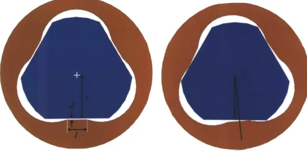
Investigation led to the realization that both the small tolerance gap and the length of the contact portion have an effect on how much the nut is able to rotate. The profiled screw (blue) and profiled nut (red) are shown in Figure 2.7. The gap and contact length are labeled as d and I respectively. The effective radius is labeled as r. The right picture illustrates the gear rotated by
50
Figure 2.7 The profiled screw (blue) and gear (red) shown aligned (left) and rotated (right).
Based on this geometry, a simple model was derived to predict the amount of rotation for a given gap (due to manufacturing tolerances), contact length and effective radius. The resulting
r+ sin E COS E = 2
r+d Equation 2.1
where e is the angle of rotation from the neutral position. The total angle of play is twice this angle of rotation. Using MATLAB's Symbolic tool box, this expression was solved for 8 for a range of contact length and gap values and the results are plotted in Figure 2.8. To validate the model, seven versions of the gear with varying contact lengths and tolerance gaps were modeled using SolidWorks. In an assembly, the profiled screw was fixed and the gears were rotated in
0.5 degree increments until a collision was detected using SolidWorks' Move Component and Collision Detection features and the angle of rotation was recorded. These angles are also included in Figure 2.8 as discrete data points.
10 6 4 2 0 I (mm)
Figure 2.8 Maximum backlash between profiled nut and shaft as a function of contact length and different tolerance
gaps calculated using a geometric model and SolidWorks.
The observations from the study in SolidWorks were consistently a little greater than the
mathematically projected results, but within half a degree, consistent with the increment used in the rotations. The results indicate that the model used is an acceptable method for predicating the angle of rotation based on the contact length and tolerance gap.
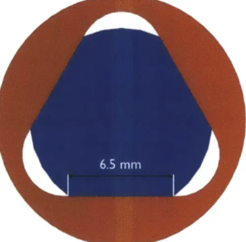
After modeling the behavior of the nuts as contact length and tolerance gaps, a final geometry with a contact length of approximately 6.5 mm was decided upon, as shown in Figure 2.9. Using this geometry, the analytical model predicted that the angular play between the screw and the nut would be about 2 degrees which was deemed acceptable for the target application.
Figure 2.9 New nut profile design (red) to ensure very little angular play with screw (blue). The contact length is about 6.5 mm.
2.4 Detailed Mechanism Design
The new transmission can be seen in Figure 2.10a. It is similar to the transmission shown in Figure 2.1 a. In the new design, the two screws are profiled as described in Section 2.2 (and seen in Figure 2.1Gb) and have threads of standard Metric M6 and Ml 1 rather than ACME threads (explained in Chapter 4). The profile of the profiled nut is the profile shown in Figure 2.9. Due to the geometry of the piece, the top of the spline, which previously was part of the screw-spline, was machined as a separate piece and attached to the screw-spline via a set screw. The profile on the top is the profile illustrated in Figure 2.6a. Different motors and pinion gears were used, as described in Chapter 3. The prototyping of the screw-spline based on this new design is described in detail in Chapter 4.
(a)
/
Threaded Nut Profiled --'ScrewK
Profiled Top
Profiled 0 Screw-Spline o Profiled NutFigure 2.10 New gear-train design (a) and profile interaction (b).
As can be seen from the figures, the overall number of parts and assembly operations is reduced due to the elimination of the key. Thus, if such a mechanism was to be used as part of a
commercial product, it could now be manufactured and assembled at a reduced cost.
3 Transmission and Actuation Sizing
The motions of the cannula and the stylet are actuated with micro-stepper motors. The design utilizes spur gears attached to the gearheads of the stepper motors that mate with the spur gear nuts that control the rotation and translation of the screw-spline and screw and therefore the cannula and stylet. In order to puncture human tissue, the cannula must pierce with a force of about ION. A reasonable speed for the cannula to travel at was determined to be about 7 mm/s from conversations with physicians. In order for the cannula to transmit a desired force at a desired velocity, the stepper motors, gearheads, and spur gear ratios must be carefully chosen. The method used to select the motors and gear ratios for the cannula follows.
The desired torque, Td , to raise a load, F , along a lead screw is
Td = Ff# 1 +2rdmsec a) Equation 3.1
where d,, is the pitch diameter, / is the lead, and a is the thread angle of the lead screw, and p is the coefficient of friction between the threads and the nut. Equation 3.1 takes into account any inefficiency due to sliding between the screw and nut. As can be seen from the equation, for a given material it will vary with the lead and diameter of the screw. The efficiency of the planetary gear head and the spur gears in the transmission also need to be taken into account when calculating the required
amount of torque, T,:
Td = lpglsg Tr, Equation 3.2
where rP. is the efficiency of the planetary gearbox and 1, is the efficiency of the spur gears.
In order to calculate the power required to create the required torque at a desired linear speed, the angular speed of the lead screw is needed. The angular speed, W),, is found with the simple calculation:
2irv
& =
-,
Equation 3.3where v is the desired linear velocity. Once the angular velocity is calculated, it is used to calculate power, Pr :
Equation 3.4
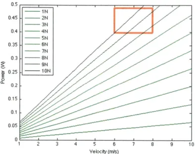
The required power is a linear function of the desired force and desired velocity, as shown in Equation 3.4. The change in required power as a function of velocity for different desired forces is shown below in Figure 3.1.
Velocity (mis)
Figure 3.1 Power required to move the cannula as a function of velocity for varying desired force. operating range is squared off in red.
Desired
For the purposes of moving the cannula with a force of ION at a speed of 7 mm/s, a power requirement of about 0.93W is required. The motor selected must therefore have a maximum power output greater than this power requirement. The motor chosen for the purpose of actuating the cannula was the Faulhaber AM1524 micro-stepper motor. The motor has a
maximum power of about 1.6 W, as shown on the torque-speed and power-speed curve in Figure
3.2.
Torque Power
(mNm) (W)
AM 1524-A-0,25-12,5-ee --- 4 2-phase ON, 0.25A, 12V
1,5
0 A
0 5000 10000 15000 20000 Speed (rpm)
2000 4000 6000 8000 (Stepis)
Figure 3.2 Torque-speed curve and power-speed for Faulhaber AM1524 micro-stepper motor. The maximum power of the motor is about 1.6 W.9
In order to calculate the required gear ratio, the output torque and output speed of the motor running at the desired power is required. For this analysis, the above torque-speed curve was
assumed to represent a brushed DC motor and the torque constant, K, and the speed constant,
K, , were estimated. This assumes that a DC motor and stepper motor of the same size would have approximately the same performance characteristics. The torque constant is calculated by using the relationship
TO = , Equation 3.5
where To is the stall torque, V is the operating voltage, and R is the terminal resistance. The
speed constant is calculated with the relationship
V
O( = -, Equation 3.6
where w0 is the no-load speed of the motor. The stall torque and no-load speed were read off of
the torque-speed curve of the motor (Figure 3.2).
The output torque of a motor, T, running at an angular velocity, 0,m, is
Tm = - Wm+ . Equation 3.7
In order to calculate the torque and angular velocity of a motor running at a power P,, Equation
3.7 is multiplied by j,. as shown in Equation 3.8.
PM= - W> + >m Equation 3.8
Solving the quadratic equation for o,, yields the motor running speed. The slower of the two
solutions was used, inputting this value back into Equation 3.7 yielding the motor running torque.
As was mentioned earlier, Equations 3.7 and 3.8 were intended for use with DC motors, where the torque-speed curves are straight lines and the maximum power is
Pmax - , Equation 3.9
which is not the case for stepper motors. In order to take into account the non-linear nature of the torque-speed curve, the curve was simplified into two linear sections of different slopes, as shown in Figure 3.3. When the motor speed calculated in Equation 3.8 is greater than 8000 rpm, the torque-speed curve is approximated as the purple dashed line. In this case, a stall torque of
2.7 mNm and a no-load speed of 22500 rpm are used to calculate the motor output torque. When
the motor speed is less than 8000 rpm, the orange dashed line approximates the torque-speed curve. In this case, a stall torque of 3.8 mNm and a no-load speed of 14500 rpm are used to calculate the motor output torque.
Torque Power
(mNm) (W)
38* AM 1524-A-0,25-12,5-ee - }-2-phase ON, 0.25A, 12V
31, 2.7k 2 0 0 18(0 145) 2250 0 5000 10000 15000 20000 Speed (rpm) 2000 4000 6000 8000 (Step/s)
Figure 3.3 Torque-speed curve and power-speed for Faulhaber AM1524 micro-stepper motor and straight line approximations. At a speed of 8000 rpm and above, the torque speed curve can be approximated as the purple dashed line, while bellow 8000 rpm it can be approximated by the orange dashed line.
Calculating the required gear ratio, r, involves finding the ratio between the required torque that was previously calculated to be 31.7 mNm using Equations 3.1 and 3.2 and the motor torque:
r = TmTr Equation 3.10
The resulting gear ratio is 8.1:1. This can be achieved by incorporating the 15A planetary gearhead from Faulhaber with a gear ratio of 14.4:1 to the motor and using a spur gear ratio of 1.4:1.
The transmission for the stylet was designed in the same manner as the transmission for the cannula. Keeping in mind the force required to retract the stylet and the force required to move
in tissue, the design specifications included a desired linear force of about 20 N, and a linear velocity of about 7 mm/s. 1.5 W of power is required for those design specifications. Using the same technique used above for the cannula, it was determined that the same motor (Faulhaber AM1524 micro-stepper motor), a 15A planetary gearhead with a gear ratio of 14.4:1, and a spur gear ratio of 1.875:1 will provide enough torque for the desired application.
Table 3.1 Parameters changed between first and second prototype.
14 Prototype 2"d Prototype
Motor AM_1020 AM_1524
Motor Steps / Revolution 20 24
Motor Holding Torque 1.6 mNm 6 mNm
Motor: Threaded Screw Nut Gear Ratio 480:1 27:1
Motor : Threaded Screw-Spline Nut Gear Ratio 32:1 20.3:1
Motor : Profiled Screw-Spline Nut Gear Ratio 32:1 20.3:1
Screw-Spline Lead 1.5875 mm 1.5 mm
4 Prototype Construction and Control
4.1 Manufacturing
The previous screw-spline and screw for the needle steering mechanism both utilized an ACME thread for power transmission. When consulting with outside machine shops for prototyping the newly designed parts (Chapter 2), they highlighted the significant cost and time that would be associated with creating an ACME thread on such small diameter rods, in particular the 6 mm diameter rod. In order to create the threads on the 6 mm rod, a custom tool would need to be made and the threads would be machined using a lathe. Thus, to avoid this, a more cost effective solution was explored. Instead of utilizing an ACME thread, the threads on the screw (6 mm diameter) and screw-spline (11 mm diameter) were designed to be M6 and M1 1. Using standard metric threads allowed the threads to be applied on to the profiled 6 and 11 mm diameter rods using a die. The pitch of the metric threads is smaller than the ACME threads (1 mm and 1.5 mm for M6 and M 11 respectively, as opposed to 1.59 mm for the ACME threads on the previous mechanism embodiment).
The new design also required that the profiled opening to the screw-spline be smaller than the cavity within the screw spline. For this reason, it was not possible to machine the screw-spline as one piece. The screw-spline was split into two pieces, the screw-spline and the top, that are attached via a set screw.
The new motors chosen for this prototype have a diameter of 15 mm, as opposed to the 10 mm diameter of the previous prototype's motors. The supports had to be adjusted to hold the new motors. The top support was modified by making the slot for the motor a 7.5 mm radius with the same center as before. If the same centers were used for the bottom supports, the slots would interfere with the bearings used in the model. Therefore, the bottom supports were modified by shifting the center of the slots and increasing the radii to 7.5 mm.
The drawings from which the parts were made from are listed in the Appendix. The
Figure 4.1 The fabricated parts: (a) screw-spline; (b) profiled top; (c) screw; (d) profiled nut; and (e) threaded screw-spline nut.
4.2 Wiring and Control
A control box that was assembled for a previous project in the Precision Engineering Research
Group was used to control the three stepper motors for the robot (Figure 4.3). This was plugged into a standard 120 V wall outlet and connected via a USB cable to a laptop computer. Inside the box are off-the-shelf components; a USB stepper motor controller, power supply and four stepper motor drivers.
Figure 4.3 Control box consisting of USB stepper motor controller, power supply, and four stepper motor drivers.
The device is controlled with a custom software interface written in Visual Basic 6. Within the code, inputs for the robot's positions are converted to motor commands taking into account the gear ratios and the screw leads. Working from a reference position with the cannula and stylet in the fully retracted positions, their positions can be controlled using a GUI. The purpose of this preliminary software interface w a s t o serve the purposes of mechanical testing and validation that are described in the chapters that follow.
The AM 1524 micro-stepper motors were purchased from Micromo and were required to be wired up to mate with the existing control box. The stepper motor data sheets (which can be viewed in the Appendix) were consulted to determine the correct wiring and a 15-pin D-sub connector was used so that a single connector could be used to easily connect and disconnect the robot from the control box. The wiring can be seen in Figure 4.4.
5 Bench-Top Evaluation
5.1 Translational Accuracy and Repeatability Axial Cannula Positioning
In order to test the accuracy of the cannula position, a series of commands, were given to the motor that meshed with the tapped nut on the cannula while the other nut was locked in place. After each command, the distance between the upper and lower supports of the robot was measured using calipers as shown in Figure 5.1. Each position was repeated three times during this test. The average value measured at each commanded position and the standard deviation of the measurements is listed in Table 5.1.
Figure 5.1 The amount that the cannula translated when commanded was determined by measuring the distance between the upper and lower supports of the robot with calipers as shown in the image.
The results are shown in Figure 5.2, where the measured distances, y, are plotted against the commanded distances, x. The line for commanded and measured distances being equal (x = y) is
Figure 5.2 Measured axial translation of the cannula compared to the commanded values. The desired relationship is shown as the red line and has a slope of 1. The line of best fit, black, has a slope of 1.0018.
The measured distances are linear, and is a very close match to the desired x = y line. The equation of the line is y = 1.0018x + 0.0209.
Table 5.1 Averages and standard deviations for the measurements compared to the command values for cannula translation.
Average Standard Deviation Measurement of Measurement Command (mm) (mm) (mm) 0 0.02 0.015 1 1.03 0.000 5 5.02 0.017 10 10.01 0.049 15 15.02 0.017 20 20.05 0.022 25 25.04 0.050 30 30.06 0.033 35 35.04 0.031 40 40.09 0.053 35 30 E 25 1 20 15 10 5 0 A 0 5 10 15 20 25 30 35 40 Command (mm)
Axial Stylet Positioning
The positioning of the stylet was tested similarly to the way the cannula was tested. A series of commands were given to the motor meshed with the tapped gear on the screw attached to the
stylet. After each command, the distance between the gear and the top of the screw was measured using calipers as shown in Figure 5.3. Each position was repeated four times during this test. The average value measured at each commanded position and the standard deviation of the measurements is listed in Table 5.2.
Figure 5.3 The amount that the stylet translated when commanded was determined by measuring the distance between the gear and the top of the screw with calipers as shown in the image.
The results are shown in Figure 5.4. The complete record of the results is included in the Appendix.
45 40 -35 E30 E GIOI S25 215 0 0 5 10 15 20 25 30 35 40 45 Command (mm)
Figure 5.4 Measured axial translation of the stylet compared to the commanded values. The desired relationship is shown as the red line and has a slope of 1. The line of best fit, black, has a slope of 1.0003.
The relationship between the measured values and the command values for the axial positioning of the stylet was similar close to the desired y = x line with an equation of y = 1.0002x + 0.0401.
Table 5.2 Averages and standard deviations for the measurements compared to the command values for stylet
translation.
Average Standard Deviation
Measurement of Measurement Command (mm) (mm) (mm) 0 0.03 0.017 1 1.00 0.024 5 5.02 0.028 10 10.07 0.009 15 15.03 0.022 20 20.04 0.016 25 25.04 0.030 30 30.06 0.016 35 35.05 0.015 40 40.05 0.022 45 45.04 0.024
Summary
The positioning of the stylet and the cannula was accurate and repeatable to the sub-mm scale
during bench-top evaluation. However, this does not correlate with the position of the tip of the stylet, which can vary due to deflection. This variability is characterized in Chapter 6.
5.2 Angular Accuracy and Repeatability Angular Position
The angular position of the robot is controlled by sending the same command to the two motors that mesh with the threaded and profiled nuts that sit on the screw-spline that is attached to the cannula. In order to determine the accuracy of the angular positioning, a protractor was taped on to the robot, and pictures after each command were taken to compare the angle of the robot to a stationary line. The setup is shown in Figure 5.5.
Figure 5.5 Picture taken after a given command. The ruler is a stationary straight edge used as a reference to calculate the angle that the robot is at. A line parallel to the straight edge is drawn (red lines) at the center point of the protractor (yellow X), and the angle at which the robot's at with respect to the straight edge can be read from the image (blue square).
A ruler was used as a constant straight edge that lined up with an angle of 0 degrees on the robot.
From the images, the angle of the robot with respect to the straight edge could be determined. The results are displayed in Figure 5.6 and more completely in the Appendix.
A rn
Figure 5.6 Measured angular displacement of the robot compared to the commanded values. The desired relationship is shown as the red line and has a slope of 1. The line of best fit, black, has a slope of 0.9962.
The relationship between the measured values and the commanded values for the angular positioning was similarly close to the desired y = x line with an equation of y = 0.9962x +
0.1875. Each position was repeated twice during this test. The average value measured at each
commanded position and the standard deviation of the measurements is listed in Table 5.3.
Table 5.3 Averages and standard deviations for the measurements compared to the command values for angular displacement.
Average Standard Deviation
Command Measurement of Measurement
(degrees) (degrees) (degrees)
-90 -89.5 0.71 0 -0.9 1.75 45 46.0 0.00 90 90.5 0.58 135 135.0 1.41 180 179.6 1.60 225 224.5 2.12 270 269.1 1.65 315 313.3 0.35 360 359.0 1.73 480-270 360 1 90 180 Command (degrees) 11% 0- f% 450
The angle of backlash was observed when the command angle of rotation changed direction. The backlash was calculated by comparing the difference in measured angle to the difference in command angle. The average angle of backlash was observed to be 2.25 degrees with a standard deviation of 1.2 degrees.
Summary
The angular positioning of the system is relatively accurate and repeatable. If not taken into account, the backlash of 2.25 degrees will shift the positioning of the robot.
6 Evaluation of Needle Steering in Ballistics Gellatin and Ex-vivo Tissue
Initial testing of the system was done in ballistics gel. Stylets of diameter 0.635 mm and 0.838 mm and curves with radii listed in Table 6.1 were deployed by the robot in gel for through a 1.2 mm internal diameter cannula. In order to do the tests, the robot was set up on a rig suspending the robot so that the needle could be inserted into gel and other mediums. The setup is illustrated in Figure 6.1.
Table 6.1 Radii of curvature of stylets tested.10
Figure 6.1 The robot is suspended by a rig allowing the needle to be inserted into various samples. 41
The stylets were deployed in gel perpendicular to the viewing field within the rig as shown in Figure 6.2.
Figure 6.2 Stylet of diameter 0.838 mm and bend of 10 mm radius deployed from cannula perpendicular to viewing field.
Images of the needle were taken, and the radii of curvature of the needles were compared to quantify the deflection of the needle in gel. The radii of curvature were measured by drawing a circle matching the radius of curvature on the image, noting the radius of the needle in pixels, and converting the radius value in pixels to mm by a conversion factor based off of a known distance in the image. The distance between two stripes on the cannula is 10 mm and the outer diameter of the cannula is 1.65 mm, so the number of pixels between the stripes or the number of pixels that make up the width of the cannula can be used as conversion factors. An example image for the 0.838 mm stylet of 10 mm radius in air is shown in Figure 6.3.
P9 9-"' Z: min
:17 29
V P! 6"
2"i Ar. MA I
rx id w ;'Pi ii. 4% W A W 4 1: " W.L' x X
Sao mass& INSDNERNNNNNN
NUNES rbREEMOMMMML9 IMMONNOMMOMME IMMEMOMMONNUM loommuminito Room& musummENUMNAMMUNNOMME NWAN a names U a anness go me a me 0:111 :109 lemons mv;' Qlww -&*us man Us
Figure 6.3 The image from Figure 6.2 with circle of diameter of 380 pixels and the conversion factor of 169 pixels in 10 mm. Therefore, the radius of curvature of the stylet is about 11 mm.
By multiplying the radius of the drawn circle (190 pixels) by the conversion factor (10 mm / 169
pixels), it can be deduced that the radius of the stylet is about 11 mm, consistent with the known radius as listed in Table 6.1. The results compiled from all of the needles in gel are displayed in Table 6.2.
Table 6.2 Results of stylet radii in gel.
Stylet Diameter Radius of Curvature Amount Stylet Radius of Curvature
(mm) (mm) Deployed (mm) in Gel (mm) 0.635 13.1 10 13.4 0.635 21.5 20 23.9 0.635 30.6 30 35.8 0.635 42.2 N/A N/A 0.838 11.2 10 11.6 0.838 21.4 20 21.1 0.838 31.1 30 32.5 0.838 40.3 40 42.0 10 mm = 169 pixels Circle D = 380 pixels
The trends illustrated in the results in Table 6.2 show that the thinner stylet deflects more than the thicker stylet, and the stylets with larger radii of curvature and are deployed further deflect more than stylets of smaller radii of curvature that are deployed less.
In order to gain information pertaining to how the needle deflects in tissue, testing was done by inserting the needles into samples of liver. A CT scanner at the Massachusetts General Hospital was used to view the position of the needles within the tissue. The rig suspending the robot was placed on the CT scanner bed above the liver sample as shown in Figure 6.4.
Figure 6.4 CT scanning test setup used to view stylet within the ex vivo tissue sample.
Before each test, after the stylets were replaced, a level was used to ensure that the rig was horizontal with respect to the scanner, and the stylet was oriented perpendicular to the scan planes. The cannula was inserted into the tissue and the stylet was deployed before the rig was moved into the scan area and the scans were performed.
Due to time constraints, four tests were done using 0.635 mm and 0.838 mm diameter stylets with radii of curvatures of 10 mm and 40 mm. The images taken by the CT scanner were saved as DICOM files. Using the software OsiriX, the DICOM files were read and manipulated. The collections of images were sliced as to view the cross-sections of the needles in which the radii of curvature were visible, as in Figure 6.5.
Figure 6.5 Slice of compilation of DICOM images showing the cross-section of the robot and needle in which the radius of curvature of the needle is visible.
Within the OsiriX software, circles with size matching the radii of curvatures of the stylets deployed in the tissue sample were drawn on the cross-sectional image, as displayed by Figure
Figure 6.6 A circle drawn on the cross-sectional image of the stylet matching the radius of curvature of the needle.
The area of the circle is displayed.
From the area of the circle depicted by the software, the radii of curvature of the needles can be calculated. The resulting radii are listed in Table 6.3.
Table 6.3 Results of stylet radii of curvature in liver.
Stylet Diameter Radius of Curvature Amount Stylet Radius of Curvature
(mm) (mm) Deployed (mm) in Liver Sample (mm)
0.635 13.1 10 14.7
0.635 42.2 40 44.3
0.838 11.2 10 12.6
0.838 40.3 40 41.3
The results from the experiment using the CT scanner to image the curved stylet within liver are listed in Table 6.2. Only one test for each stylet was managed in the allotted time with the CT scanner. More tests would allow for a validated result and to quantify the variability in the experimental measurement technique. With more testing and data, the position of the tip of the stylet can be predicted for the different mediums. Therefore, the position of the tip of the stylet can be more accurately positioned during clinical procedures.
7 Conclusions and Future Work
The goal of this thesis was to create a robust functioning prototype that performs more reliably than a previous model, as well as develop design tools that allow the design to be scaled for
different applications.
A new screw-spline mechanism was created using a profiled shaft and matching nut rather than
spline and key. This mechanism can be easily and cheaply constructed from plastic components, and can be manufactured at a larger scale by injection molding. A model based on the geometry of the screw and nut was developed to characterize the performance of the profile mechanism. This model was validated using SolidWorks and the prototyped screw-spline and nut had an angular play of approximately 2.25 degrees that was matched well with the value of 2 degrees predicted by the mathematical model.
A deterministic method for selecting appropriate stepper motors was developed in order to
replace the AM1020 stepper motors used in the first prototype. The stepper motors selected were Faulhaber AM1524 stepper motors with the 15A planetary gearhead attachment. The use of these motors increased the torque and power of the system, ensuring the device did not stall, and operated at a faster pace.
The device was tested for accuracy and repeatability for axial translation of the stylet and
cannula, and angular displacement. Results of the tests show that the robot has sub-mm accuracy and repeatability. Evaluation of the mechanism demonstrated that it could be used to perform needle steering in both ballistics gelatin and ex-vivo liver tissue. In both gelatin and ex vivo liver tissue, the thinner stylets consistently deflected more than the thicker stylets as would be expected. The amount of deflection based on the curvature of radius and distance deployed of the stylet also behaved as expected: the stylets with larger radii of curvature were deployed further and deflected more than the stylets with smaller radii. More testing is required to validate the experimental protocols to ensure that measurement accuracy and variability are known. The major result of this thesis is a robustly functioning drive mechanism for a robotically steered needle that can now be integrated with a thermal ablation probe. Before this happens, further testing of different stylets in gel and ex-vivo tissue would allow for a more accurate
characterization of the targeting accuracy of such a system. Being able to predict the position of the end of the stylet would be important for targeting small tumors or accurately targeting multiple adjacent points in a volume. Another potential application for the mechanism is for needle steering with a pre-curved needle so that physicians could correct for targeting errors as a curved needle is being deployed.
References
1 Singer, Emily. "The Slow Rise of the Robot Surgeon." Technology Review. 24 March 2010.
http://www.technologyreview.com/biomedicine/24850/.
2 Bourzac, Katherine. "Robotic Guidance for Knee Surery." Technology Review. 27 March
2008. http://www.technologyreview.com/biomedicine/20475/.
3 Camarillo DB, Krummel TM, Salisbury JK. Robotic technology in surgery: Past, present, and
future. American journal of surgery 2004; 188:2-15.
4 Goldberg SN, Grassi CJ, Cardella JF, et al. Image-guided Tumor Ablation: Standardization of Terminology and Reporting Criteria. Radiology 2005; 235:728-739.
5 C.J. Walsh. "Image-Guided Robots for Dot-Matrix Tumor Ablation." Diss. Massachusetts
Institute of Technology, Cambridge, 2010.
6 Ahmed, M., Brace, C., Lee, F., Goldberg, S.. "Principles of and Advances in Percutaneous
Ablation." Radiology, Vol 258: No 2. February 2011, 351-69.
7 "Polygon Profiles." General Polygon. 2009. 17 March, 2011.
http://generalpolygon.com/profiles.htm.
8 Shigley, Joseph and Charles Mischke. Mechanical Engineering Design. 6th ed. Boston: McGraw Hill, 2001.
9 "2-Phase Stepper Motors." Micromo: Micro Motion Solutions. 2011. 4 April, 2011.
http://catalog.micromo.com/db/service?domain=micromo&command=locate&category= 2_phase-stepper-motors.
1 Walsh, C., Franklin, J., Slocum, A., Gupta, R. Characterization of Pre-curved Needles for Use in Distal Tip Manipulation Mechanisms (paper, poster and oral presentation), ASME Design of Medical Devices Conference, April 13-15, 2010.
-0.03
-0.0807
54 8-0.05
00.75 0.00 ID B B M4 Tapped Hole M] l 1.5 Thread 4.50 0.00 0.05 SECTION B-B Cf APE i mmAt. .WLAP: MACt.t O.S deg
PR-MME MCCNEM04K ?itf'GPiAAtCO%. AN7E1i0 N
r. IY PEPCOCTO. "1. PA7 0.
A: A W-CLE WU'MC Wt -E7
PQC"tEiR.
SolidWorks Student License
Academic Use Only
?efrr
MIT
-
Steedle
orrn~r G~.'~: ECcfen-$o| ne :Crew~I0~
023-0.05
2.30 0.000
03.5 Bolt
,Note: .1ill sharp
corners between bolt
circle holes flot
4-40 Tapped Hole
Cite s~t 1U AREI I y ToiEQArICE:
X~xt 0 35s
ArLULA: A&C-t 0-1 deg
PiR COUAO CAN ED MME
DZA41iX Ir GCL.E 94Pf;'PEF
MTi. Ar7 i EMOCDCT0h fl PAr O
A. A UM l WU ,E D
PERMS1OtI Of r~ C
PQCtMblr.
2.5
SolidWorks Student License
SECTION A-A SCALE 2: 1
j
01 toppe ta 2.30 A dSolidWorks Student License
Academic Use Only
I
A.:M N E - X l PA1iO AZ A V0,CLE WTMCW MfW;T j -Fillet corners so rot sharp -A6 x1 Thread 0 OLETAr.iCEZ A.XXtA 0CS At 4GULAQ: MA QCH~ 0.5 ceg I - : 'j- C, --- , . .
S0.1 A -M6 x 1 topped thread SECTION A-A SCALE 2: I P MI_:Ct ,, ARE: i MM T: At," E: X 0.1 ANALQ:MAt-t0.5deg
Mi
raP~~tcc JnoNT
DRCPM.E40W CONCETN O .'.A R#9DUCO. Ptr o; A A NCLE Wrs0V -B'W V W PESC" Cof M- G PRCHEUE.SolidWorks Student License
Academic Use Only
MIT -
steedle
M d
Fo A cet Ge r 617-_10-r m 0
Topped omm
core -,u gea?
f
12.0
A
1 x .5 threaded bore SECTION B-B SCALE 2 : 1 DM-AVC -- (4 AnE ti m *0.E;Ar CE3: x X 0.1 m i.A : M C0. aeg
Pil V1A M OMiA M ff@A0 COMAt ED ir ?HZ A: A MCLE W1MCT T Wif"*EI
Efpt:o or fr C
PRCH ErE.
SolidWorks Student License
Academic Use Only
5.50
Note: Stock oart to be modified
3x 120*
Diameter
R7.5
R2.5
Close slidirg fit with Profiled Screw (Provided) CWatCARE it I mv"
X t t .
X ,xx t Ol.05
AridLA:MCt-t 0,5deg
tMOmvAR, AN COMtNIOAL tj PC.ArCq CO Jt MD I I TN!
D;AMkrt - 4 :CtE PQCPET! Of ?r.: At . ?SQCOILCTjt.VPAr 0r
SolidWorks Student License
FAULHABER
C~tennar Mnttrc i; fl mMm
Two phase, 24 steps per revolution PRECtstep* Technology
I NM W vm s
2 P~Natfta 4uriowt pat pbhiu (bcth pkusc ONIJ
3 Pt.;* reastwstco (at 20,1 A Womductaec(1k14J
3 wak IM W npftrudo
6 4o1idwr t*Orqm (*t nomiral curront or~ be+h pI'.io "0"lin toeqwu ! (at twios Ow nhdvont111)
9 Ariguty wwostcy
10 Ra" trque
I1I Rotor Itrtiz
12 Roann. freq emrtat no ioac4
1) DoeMkal thn4 costan
14 Ariford tormfporature rargo
16 1omn oatrc tdn bo aif
17 thom. twn. Constont 18 Slsaft beenwgs 19 Shaft kie "WK.: - adWa Q mm ftcm borIg 20 $Aaft m _ =ir:l~,N -.waO0m 21 koltuonteatvaltge 22 Weigh 6.0 10 a 10 0.9 4S 120 130 3? 220
Wi mWred m das oom bmN bawm9gs
-fofa
(stan4wco rOptlmor" -0.S 6.0 O~s 2.0 is 12 iso -" wtt% b-"1w firtoA2 phase OK. baloacd phso aromb
C urwm ag.rod wh a l~row wla of t10 10 9kgm:
"TOM904 WAw at lasvor04 9ft In amon owtVlt visa dwmm eto atstjtrspook .mn v sauuwrga raw ~7~.~'tt 9.1
Hi
WbW"INW * 71A.o~~~% s iee it aer
wx 0a
Dtsw AD CMMIS
14t vmte a o10&~c4 dau 0d h461st-t P.4m...ant
'3w
.4w 11I ~ In
:1
4.1.1I
0
R RT PrALANE CWo C$g-~U~w
MJJI-o
*WPO tt
11WO431flubwI to" "m ai =0 4m 40 0O 0 110 A A mmm r"WOR INK %"W"-t!iillOl
I1
I.
I
£A
Oa~ Ill -ILL AltTable Al Axial cannula positioning data Command Measured (mm) (mm)