HAL Id: hal-01631535
https://hal.archives-ouvertes.fr/hal-01631535
Submitted on 9 Nov 2017
HAL is a multi-disciplinary open access
archive for the deposit and dissemination of
sci-entific research documents, whether they are
pub-lished or not. The documents may come from
teaching and research institutions in France or
abroad, or from public or private research centers.
L’archive ouverte pluridisciplinaire HAL, est
destinée au dépôt et à la diffusion de documents
scientifiques de niveau recherche, publiés ou non,
émanant des établissements d’enseignement et de
recherche français ou étrangers, des laboratoires
publics ou privés.
against horizontal forces
H Wadi, Sofiane Amziane, M Taazount
To cite this version:
H Wadi, Sofiane Amziane, M Taazount. Mechanical behaviour of unclassified timber walls against
horizontal forces. 35èmes Rencontres universitaires de génie civil de l’AUGC, May 2017, Nantes,
France. �hal-01631535�
Mechanical behaviour of unclassified timber walls against
horizontal forces
H. Wadi
1,2, S. Amziane
1,2, M. Taazount
1,21 Université Clermont Auvergne, Institut Pascal, BP 10448, F 63000 CLERMONT-FERRAND, FRANCE
2
CNRS, UMR 6602, IP, F-63178 Aubière, France.
husam.wadi@etudiant.univ-bpclermont.fr
sofiane.amziane@uca.fr
mustapha.taazount@uca.fr
RÉSUMÉ.
Cette étude concerne le comportement mécanique de murs en bois, réalisés avec des planches croisées en bois non classé, sous l’effet de forces horizontales de cisaillement. Chaque mur se compose de trois plis de planches maintenues par des pointes métalliques dans leurs plans de croisement (2 pointes par plan de croisement) : deux plis verticaux et un pli horizontal. Ce travail se consacre à l’étude expérimentale de la capacité de résistance au contreventement de modules de murs de dimension de 1,2m de largeur 2,5m de hauteur. Nous proposons une méthode de calcul numérique d’évaluation de la capacité portante du mur. Les résultats expérimentaux et numériques sont comparés à ceux obtenus pour des murs à panneaux d’OSB (Oriented Strand Board). Des analyses et commentaires ont été aboutis sur l’utilisation réelle de ces murs en bois dans les constructions de génie civil en capacité portante et en exploitation de service.
ABSTRACT.
This study concerns on the mechanical behavior of unclassified timber walls under horizontal forces. Each wall consists of three cross layers of wooden planks connected together by fasteners in their plane of intersection (2 fasteners per plane of crossing): two vertical layers and one horizontal. This work is related to an experimental study of timber walls in order to investigate the lateral load resistance of the wall with dimensions 1.2m width and 2.5m height. We proposed a numerical method for calculating the load carrying capacity of the wall. The experimental and numerical results are compared with OSB panels (Oriented Strand Board). Analyses and recommendations have been made for using these wooden walls in load carrying capacity in construction of civil engineering and service operation.
1. Introduction
Timber walls are the structural system in the buildings that designed for the purpose of resisting lateral loads and transmitting these forces to the foundations in a ductile behavior [1]. According to the European Standard EN 594, [2] the timber shear wall consists of timber frame and sheathing board connected together by fasteners. The sheathing board can be from different materials such as Gypsum, Plywood, Fibre board and OSB [3]. In this study, the methodology of cross planks wall has been investigated experimentally against the lateral load and an elastic analytical model has been created to describe the behavior of these walls and calculating the load carrying capacity.
2. Analytical modelling of cross planks wall unit
This wall consists of crossing vertical and horizontal planks, each plane forms a fold (horizontal or vertical). The total number N of folds is constituted by an odd number Nv of vertical planks and an even or odd number NH of
horizontal planks, as illustrated in figure 1. A fold is formed by a number of planks (Npx for vertical folds and Npy for horizontal folds) forming its total width or height. The planks are characterized by a width e (10 e 15 cm) and a thickness d (2d3cm), generally constant (ex = ey = e); as illustrated in figure 2:
1 / 2 1 / 2 V H N N N N (1)
1 1 1 2 m px py m m V px py N N N N N N N N N (2)
2 2 1 2 1 5 5 10 2 2 2 y x e e r r r d d e d (3)The height of the wall varies from 2 to 3 m, its width (a) varies also from 1 to 1.2m and its thickness (b) depends on the total number N of the folds. Each mesh plank intersection is assembled by two nails ensuring the connection, in each case, between a vertical fold and a horizontal one. The nails are anchored respecting the edge distances of 5d (EC5) and located at a distance r1 = r2 = r with respect to the geometrical center "o" of the mesh.
Figure 1: The formation of the cross plank wall unit. Figure 2: The internal resistance of one mesh
The formation of these walls is generally automated and the configuration of all meshes is almost homogeneous. The number Nm1 of meshes per shear plane and their total number Nm are given respectively by the previous formulas.
The fasteners are subjected to the resistance due to the internal forces and the relative movement between planks. The total number of fasteners is equal to (2) x (Nm) and each fastener is manifested by its ultimate force in single shear Fv,Rk:
The lateral load carrying capacity of a cross-plank wooden wall is ensured by the rotational resistances of the crossover planks which develop a moment in ultimate resistance given by the following equations:
, ,R 1 2 ,R 1 2 10 m x y N v Rk v k v k m e e e i i M F r r F N e d
(4)
While sliding, each nail anchor in the wood can be represented by a spring Kser, and the equilibrium of a crossing
mesh is ensured by a rotational stiffness K. By applying the energy conservation theorem, the rotational rigidity of each mesh of index "i" is obtained by:
2 2
2 1 2 10 i x y ser i ser i e e e K K r r K e d Consequently, the total rotational rigidity is obtained by summation over the set of cross planks.
2
2 1 1 10 10 m m i x y N N ser i ser m i i e e e K K K e d K N e d
(5)
Four hypotheses have been made for the distribution of the internal forces and the top displacement of the wall. The first hypothesis is based on the assumption that the distribution of the external force on the crossover meshes is proportional to the rotational rigidities. The second hypotheses is based on the static equilibrium of the wall by equality between external moments (taken from the base of the wall) and the interior. The third hypotheses is to calculate the top displacement of the wall according to application of the theorem of energy conservation between the work of the external force and those in the meshes. The fourth hypotheses is to calculate the ultimate force.
1 2 2 10 2 10 i i te i x y x y V d m K C e e e e e e M M e F F r r e d e d N (6)
, 2 10 x y V d V Rd m e e e h F F F N e d (7)
Proposition 1: Equilibrium of a cross-over mesh Proposition 2: Equilibrium of moments
2 2h F K (8)
, ,R 10 2 ex ey e U k m v k e d F N F h (9)
Proposition 3: The top displacement of the wall Proposition 4: Ultimate force
3. Experimental study
Nine samples of wood were tested for compressive strength to classify the type of wood and to determine the characteristics of wood material, five samples were tested in parallel to the grain of wood and four samples were tested in transverse to gain of wood. The average compressive strength parallel to grain of wood (fc,0,k) was 29.9 MPa
and the average compressive strength perpendicular to the gain of wood (fc,90,k) was 4.2 MPa. Taking in to account
the compressive strength and the mean density of the material (ρ = 463.4 Kg/m3) and comparing these three values with wood classification of Eurocode (5) NF EN 1194, the closest class of this wood material is C30. Three tests were examined to determine the load carrying capacity of fasteners, double shear timber-to-timber with three pieces connected using two nails per side. The nails used were rounded cross-section 2.5 mm of diameter and length 45 mm.
The mean value of the maximum load for fastener
Fv,R,meanwas 1.59 KN.
3.1 Racking tests of cross plank wall
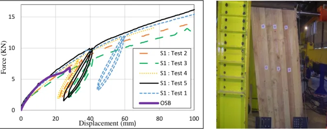
Five walls of large scale timber cross planks were used, each wall of cross planks consists of three layers and the connection of these layers is done using rounded nails of diameter 2.5 mm and 45 mm long. The walls were 250 cm in height, 120 cm in width and 7.5 cm in thick. A horizontal racking load was applied to the top of wall by a hydraulic jack as illustrated in figure 10. One timber frame with oriented strand board was used with height 300 cm, width 121cm and thickness 13.5 cm. The wall was fixed to the floor to avoid sliding, a horizontal load was applied to the top of the panel with the same previous techniques. The wall was consisting of three columns (studs) and OSB3 sheet.
Figure 3: Force-Displacement behaviour. Figure 4: Timber cross plank wall in test.
4. Calculations and discussion
The lateral load carrying capacity (Fv,Rk) for the nails used in cross plank wall has been calculated according to the
Eurocode 5 formulas and it was 616.66 N. The ultimate horizontal force at the top of the wall has calculated based on the proposition 4 and it was 11.16 KN with a top displacement 50.40 mm. considering the factor of safety equal to 1.3 then the design force of the wall will be 11.16/1.3 = 8.58 KN. The internal force on each nail as a proportional of the rotational rigidities and based on the first proposition was Fi = 74 N but considering to the second assumption of
moments equilibrium, the internal force at the nail was 616.66 N.
Proposition 1 Proposition 2 Proposition 3 Proposition 4
Fvd (N) 74 N 616.66 N ---- ----
∆ (mm) ---- ---- 50.40 mm
Fu,k (KN) ---- ---- ---- 11.16 KN
Due to the creation of internal rotational moments in each shear plane as illustrated in figure 2 the cross plank walls are able to resist a lateral forces and can be more rigidity in behavior than OSB panels.
5. Conclusion
The behavior of cross planks walls made from unclassified timber proved a greater resistance and more rigidity than OSB panel due to the huge numbers of internal rotational moments that created in each shear plane in the wall. An analytical model has been created to represent the internal forces on each fastener and calculating the ultimate force on the top of the wall. This wall has a good performance in construction of civil engineering to resist the lateral loads.
6. References
[1] Wei Y. Loo, Pierre Quenneville, Nawawi Chouw. A numerical study of the seismic behavior of timber shear walls with slips-friction connectors. Engineering Structures 34 (2012) 233-243.
[2] European Standard. Timber structures-test methods- racking strength and stiffness frame wall panels, European Committee for Standardization (2006).
0 5 10 15 0 20 40 60 80 100 Fo rce ( KN) Displacement (mm) S1 : Test 2 S1 : Test 3 S1 : Test 4 S1 : Test 5 S1 : Test 1 OSB
[3] Johan Vessby, Erik Serrano, Anders Olsson. Coupled and uncoupled nonlinear elastic finite element models for monotonically loaded sheathing-to-framing joints in timber based shear walls. Engineering Structures. 32 (2010) 3433-3442.