HAL Id: hal-00301492
https://hal.archives-ouvertes.fr/hal-00301492
Submitted on 4 Nov 2004HAL is a multi-disciplinary open access archive for the deposit and dissemination of sci-entific research documents, whether they are pub-lished or not. The documents may come from teaching and research institutions in France or abroad, or from public or private research centers.
L’archive ouverte pluridisciplinaire HAL, est destinée au dépôt et à la diffusion de documents scientifiques de niveau recherche, publiés ou non, émanant des établissements d’enseignement et de recherche français ou étrangers, des laboratoires publics ou privés.
Technical Note: The Modular Earth Submodel System
(MESSy) ? a new approach towards Earth System
Modeling
P. Jöckel, R. Sander, J. Lelieveld
To cite this version:
P. Jöckel, R. Sander, J. Lelieveld. Technical Note: The Modular Earth Submodel System (MESSy) ? a new approach towards Earth System Modeling. Atmospheric Chemistry and Physics Discussions, European Geosciences Union, 2004, 4 (6), pp.7139-7166. �hal-00301492�
ACPD
4, 7139–7166, 2004The Modular Earth Submodel System P. J ¨ockel et al. Title Page Abstract Introduction Conclusions References Tables Figures J I J I Back Close Full Screen / Esc
Print Version Interactive Discussion
© EGU 2004
Atmos. Chem. Phys. Discuss., 4, 7139–7166, 2004 www.atmos-chem-phys.org/acpd/4/7139/
SRef-ID: 1680-7375/acpd/2004-4-7139 © European Geosciences Union 2004
Atmospheric Chemistry and Physics Discussions
Technical Note: The Modular Earth
Submodel System (MESSy) – a new
approach towards Earth System Modeling
P. J ¨ockel, R. Sander, and J. Lelieveld
Max Planck Institute for Chemistry, P.O. Box 3060, 55020 Mainz, Germany
Received: 17 September 2004 – Accepted: 12 October 2004 – Published: 4 November 2004 Correspondence to: P. J ¨ockel ([email protected])
ACPD
4, 7139–7166, 2004The Modular Earth Submodel System P. J ¨ockel et al. Title Page Abstract Introduction Conclusions References Tables Figures J I J I Back Close Full Screen / Esc
Print Version Interactive Discussion
© EGU 2004 Abstract
Generally, the typical approach towards Earth System Modeling has been to couple existing models of different domains (land, ocean, atmosphere, . . . ) offline, using out-put files of one model to provide inout-put for the other. However, for a detailed study of the interactions and feedbacks between chemical, physical, and biological processes,
5
it is necessary to perform the coupling online. One strategy is to link the existing domain-specific models with a universal coupler. In many cases, however, a much simpler approach is more feasible. To achieve the online coupling, we have developed the Modular Earth Submodel System (MESSy). Data are exchanged between a base model and several submodels within one comprehensive model system. MESSy
in-10
cludes a generalized interface structure for the standardized control of the submodels and their interconnections. The internal complexity of the submodels is controllable in a transparent and user friendly way. This provides remarkable new possibilities to study feedback mechanisms (by two-way coupling), e.g., by applying MESSy to a general circulation model (GCM).
15
1. Introduction
A new approach in global environmental computer modeling is to pursue Earth System models. The aim is to capture feedback mechanisms between the traditional com-ponents as defined within the geosciences, i.e. the atmosphere, hydrosphere, litho-sphere, pedolitho-sphere, biolitho-sphere, and ultimately also the anthroposphere. In the past,
20
many component models used pre-calculated data sets (offline models) to circumvent computational constraints. Since the large data sets involved call for large storage ca-pacity, especially at high time resolution, a number of processes could only be updated occasionally. Data for intermediate periods were interpolated in time, and small-scale or rapidly proceeding processes were parameterized, leading to a loss of accuracy and
25
stor-ACPD
4, 7139–7166, 2004The Modular Earth Submodel System P. J ¨ockel et al. Title Page Abstract Introduction Conclusions References Tables Figures J I J I Back Close Full Screen / Esc
Print Version Interactive Discussion
© EGU 2004
age capacity to become a limiting factor. Furthermore, the time resolution required for one component may not match that of the other. The obvious solution is to interactively compute all processes at relatively high and flexible time resolution, which reduces the need to store data, and which allows capturing interactions and feedbacks previously suppressed by interpolation or parameterization. On the other hand, more
comprehen-5
sive and complex models are more difficult to handle and require increasingly powerful computers. Our philosophy to pursue an interactively coupled Earth System model ap-proach is partly based on the expectation that computational power will increase more rapidly than data storage and handling capacity. In this technical note we present the requirements, the outline and the implementation of our model structure.
10
Whereas in the early phase of the development most of the “historically grown” mod-els have been designed to address a few very specific scientific questions in a spe-cific geophysical domain, the codes have been continuously further developed over decades, with steadily increasing complexity. An increasing number of processes has been taken into consideration, so that the computability was usually close to the limits
15
of the available resources. These historically grown model codes are now in a state associated with several problems:
– The code has mostly been developed by scientists, who are not necessarily well-trained programmers. In principle every contribution follows its developers unique style of programming. Coding conventions (e.g.http://www.meto.gov.uk/research/ 20
nwp/numerical/fortran90/f90 standards.html) only help when strictly adhered and when code reviews are performed on a regular basis.
– The code has not been written to be easily extendable for and adaptable to new scientific tasks.
– There has been little motivation for writing “good” (i.e. readable and robust) code, 25
since the scientific aim (i.e. only the model output) had to be reached rapidly and uniquely. The only measure of code quality has been the question whether it is
ACPD
4, 7139–7166, 2004The Modular Earth Submodel System P. J ¨ockel et al. Title Page Abstract Introduction Conclusions References Tables Figures J I J I Back Close Full Screen / Esc
Print Version Interactive Discussion
© EGU 2004
running (good) or not (bad). Well structured, readable code has usually received little priority.
– Documentation lines within the code are often rare or absent.
– The code has been developed to run in a few specific configurations only, e.g. in a particular vertical and horizontal resolution, parameterizations are resolution
5
dependent, etc.
– The code contains “hard-coded” statements (e.g. parameters implemented ex-plicitely as numerical values), which require recompilation after changes, e.g. for sensitivity studies.
– In many cases code developers (e.g. PhD students) are no longer available for 10
support and advice. If insurmountable obstacles occur, the code has to be rewrit-ten completely.
– Outdated computer languages (mostly Fortran77 or older) limit the full exploitation of available hardware capacities. Therefore, the codes have been “optimized” for specific hardware architectures, using non-standard, vendor-specific language
15
extensions. As a consequence, these codes are not portable to other platforms without major changes.
– Compilers have been highly specific and error tolerant, e.g. some even allowed divisions by zero. Although this may seem an advantage, it must be stressed that potentially serious code flaws are masked, which makes error tracing extremely
20
difficult.
The result is often a highly importable, unreadable, undocumented “spaghetti-code”, which inhibits an efficient further development. The same problems have to be solved time and again. The use of submodels/routines in a different environment requires in many cases incommensurate efforts. Even worse than this development aspect is
ACPD
4, 7139–7166, 2004The Modular Earth Submodel System P. J ¨ockel et al. Title Page Abstract Introduction Conclusions References Tables Figures J I J I Back Close Full Screen / Esc
Print Version Interactive Discussion
© EGU 2004
the fact that those complex, non-transparent computer programs elude more and more understanding, apart from a small, indispensable group involved from the beginning.
These problems might call into question the feasibility of the next step, the transition from domain specific models of the Earth’s Environment towards comprehensive Earth System Models (ESMs). One popular approach is to couple the existing domain
spe-5
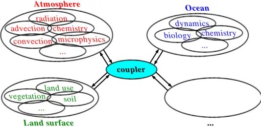
cific models as they are via an external “coupler”, which handles the communication (data-exchange) between the domain models (Fig.1).
This approach is followed for instance by the PRogram for Integrated earth System Modeling (PRISM,http://prism.enes.org/) and the Earth System Modeling Framework (ESMF,http://www.esmf.ucar.edu/).
10
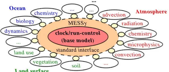
However, this concept might not be sufficient for the development of an understand-able, traceunderstand-able, complex ESM. Increasing complexity requires an equally increasing degree of transparency in the models. One single user, focusing on a specific scientific question, is unable to grasp the whole model setup. Still, she/he must be able to control it. For this also the domain specific models need some re-configuration (“cleanup”), as
15
outlined in Fig.2.
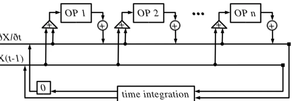
The base idea is to modularize the different specific processes, i.e. to implement them as submodels and separate them from the remaining base model. This is the consistent application of the operator splitting (Fig.3), which is implemented in such models anyway. In offline models operator splitting is a problem because the time
res-20
olution of some process calculations is low. In relatively high resolution online models this problem systematically decreases.
It must be stressed that both the domain-oriented approach, and the process-oriented approach are not exclusive. Both approaches can be combined. For example, the domain specific models may be implemented following the process-oriented
ap-25
proach and then coupled by following the domain-oriented approach using an external coupler. This combination allows a flexible, efficient, problem-oriented development of ESMs based on existing codes.
ACPD
4, 7139–7166, 2004The Modular Earth Submodel System P. J ¨ockel et al. Title Page Abstract Introduction Conclusions References Tables Figures J I J I Back Close Full Screen / Esc
Print Version Interactive Discussion
© EGU 2004
In Sect.2the needs for a successful Earth System Model are set out in more detail, and suggestions on how to meet these requirements are elaborated. The implementa-tion of these ideas as the “Modular Earth Submodel System” (MESSy) is presented in Sect.3. Finally, Sect.4suggests possible applications.
2. Objectives 5
In order to achieve a highly consistent, physically correct, flexible, extendable Earth System Model, the following requirements must be met:
– Flexibility: Several alternative implementations for the same process can coexist in the same model system, e.g. different parameterizations for sensitivity studies, different approaches for process studies, “frozen” and developer versions can be
10
directly compared.
– Plug & play: The implemented processes can be easily exchanged between dif-ferent model systems.
– Test facility: The implemented processes can be tested without running the entire model system, i.e. for instance coupled to a simple box model (see Sect.4.1).
15
– Security: Parameterizations can introduce large errors if they are used outside their valid range. Such unwanted or uncontrolled extrapolations should be avoided by terminating the model system if a parameterization gets out of range.
– Coupled system: Feedback mechanisms can be easily implemented, controlled, and quantified.
20
– Multi-purpose: The model system can be applied to a wide range of scientific questions, especially with respect to spatial and temporal scales, the processes involved, and the domains covered.
ACPD
4, 7139–7166, 2004The Modular Earth Submodel System P. J ¨ockel et al. Title Page Abstract Introduction Conclusions References Tables Figures J I J I Back Close Full Screen / Esc
Print Version Interactive Discussion
© EGU 2004 – Portability: The model system is highly portable and runs on various different
computer architectures.
– Expandability: The model system structure allows the straightforward adaption of additional processes and is prepared for future contributions.
– Multi-developer: The model system can be further developed by more than one 5
person at the same time without interference.
– Consistency: The model system is highly consistent, all implemented processes share the same fundamental data sources.
– Efficiency: The model system code is highly efficient regarding usage of computer (processor) time.
10
– Reproducibility: Re-compilation of the code is avoided whenever possible, at least within one model simulation including sensitivity studies. Especially the choice of process specific parameters, the coupling of different processes, and the choice of available alternatives should not require a code recompilation. Note: In cou-pled complex (non-linear) systems, re-compilation bears the risk of loosing
repro-15
ducibility due to uncontrollable compiler issues.
– Variable complexity: The internal complexity of each process can be changed according to its relevance in different applications.
– Synergy: Implementations relevant for different processes are shared.
– User friendly: The model system comprehends a unified, transparent user inter-20
face for the control of the model system.
All these aims can be reached simultaneously, if at least the following prerequisites are accounted for:
ACPD
4, 7139–7166, 2004The Modular Earth Submodel System P. J ¨ockel et al. Title Page Abstract Introduction Conclusions References Tables Figures J I J I Back Close Full Screen / Esc
Print Version Interactive Discussion
© EGU 2004 – Modularity: Each specific process is coded as a separate, independent entity, i.e.
as a submodel, which can be switched on/off individually.
– Standard interface: A so-called base model provides the framework to which all submodels are connected. At the final state of the development the base model should not contain more than a central clock for the time control (time integration
5
loop) and a flow control of the involved processes (=submodels). This ultimate aim can be reached step by step. For instance one could start from an existing GCM (as in our example) and connect new processes via the standard interface. At the same time, it is possible to modularize processes which are already part of the GCM, and reconnect them via the standard interface. In many cases this
10
requires only a slightly modified reimplementation based on the existing code. – Self-consistency: Each submodel is completely self-consistent, the submodel
out-put is completely defined by its numerical inout-put.
– Resolution independent: The submodel code is completely independent of the spatial (grid) and temporal resolution (time step) of the base model. If
applica-15
ble and possible, the submodels are also independent of the dimensionality (0-D (box), 1-D (column), 2-D, 3-D) and the horizontal (regional, global) and vertical domain of the base model. Each process is coded for the smallest applicable entity (box, column, column-vector, . . . ).
– Data flow: Exchange of data between the submodels and also between a sub-20
model and the base model is standardized.
– Soft-coding: The model code does not contain any “hard-coded” specifications which require a change of the code and recompilation after the model domain or the temporal or spatial resolution is changed. A prominent example is to use height or pressure for parameterizations of vertical profiles, instead of level
in-25
dices, as the latter have to be changed if the vertical resolution of the base model is adjusted.
ACPD
4, 7139–7166, 2004The Modular Earth Submodel System P. J ¨ockel et al. Title Page Abstract Introduction Conclusions References Tables Figures J I J I Back Close Full Screen / Esc
Print Version Interactive Discussion
© EGU 2004 – Portability: All submodels are coded according to the language standard of
For-tran95 (ISO/IEC-1539-1). The submodel code is free of hardware vendor specific language extensions. In the rare cases where hardware specific code is unavoid-able (e.g. to circumvent compiler deficiencies), it is encapsulated in preprocessor directives.
5
3. Implementation
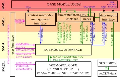
In order to meet the objectives described above, we have developed the Modular Earth Submodel System (MESSy). The MESSy interface connects the submodels to the base model via a standard interface. As a result, the complete model setup is organized in four layers, as shown in Fig.4:
10
1. The Base Model Layer (BML): At the final development state, this layer com-prises only a central time integration management and a run control facility for the processes involved. In the transition state (at present) the BML is the domain specific model with all modularized parts removed. For instance, in case of an atmospheric model it is usually a GCM.
15
2. The Base Model Interface Layer (BMIL), which comprises basically three func-tionalities:
– The central submodel management interface allows the base model to con-trol (i.e. to switch and call) the submodels.
– The data transfer/export interface organizes the data transfer between the 20
submodels and the base model and between different submodels. It is fur-thermore responsible for the output of results (export). Based on the require-ments of the model setup, the data can be classified according to their use, e.g. as physical constants, as time varying physical fields, and as tracers (i.e. chemical compounds).
ACPD
4, 7139–7166, 2004The Modular Earth Submodel System P. J ¨ockel et al. Title Page Abstract Introduction Conclusions References Tables Figures J I J I Back Close Full Screen / Esc
Print Version Interactive Discussion
© EGU 2004 – The data import interface is used for flexible (i.e. grid independent) import of
gridded initial and time dependent boundary conditions.
The BMIL therefore comprises the whole MESSy infrastructure which is organized in so called generic submodels (see Appendix A).
3. The Submodel Interface Layer (SMIL): This layer is a submodel-specific interface,
5
which collects all relevant information/data from the BMIL, transfers them via pa-rameter lists to the Submodel Core Layer (SMCL, see below), calls the SMCL routines, and distributes the calculated results from the parameter lists back to the BMIL. Since this layer performs the data exchange for the submodel, also the coupling/feedback between different submodels is managed within this layer.
10
4. The Submodel Core Layer (SMCL): This layer comprises the self-consistent core routines of a submodel (e.g., chemical integrations, physics, parameterizations, diagnostic calculations, etc.), which are completely independent of the implemen-tation of the base model. Information exchange is solely performed via parameter lists of the subroutines. The output is completely determined by the input.
15
The user interface is implemented by using the Fortran95 namelist constructs, and is connected to the three layers BMIL, SMIL, and SMCL (see Appendix B).
The global switch to turn the submodel on/off is used in the BMIL. These switches for all submodels are set by the run script (see Appendix B).
Submodel-specific data initialization (e.g. initialization of chemical species (
=trac-20
ers)), and import of data within the time integration (e.g. temporally changing boundary conditions) using the data import interface are handled by the SMIL. Within the SMIL, also the coupling options from the user interface are evaluated and applied, which control the coupling of the submodel to the base model and to other submodels. For instance, the user has the choice to select the submodel input from alternative sources,
25
ACPD
4, 7139–7166, 2004The Modular Earth Submodel System P. J ¨ockel et al. Title Page Abstract Introduction Conclusions References Tables Figures J I J I Back Close Full Screen / Esc
Print Version Interactive Discussion
© EGU 2004
Therefore, this interface allows a straightforward implementation and management of feedback mechanisms between various processes.
The control interface is located within the SMCL and manages the internal complexity (and with this also the output) of the submodel. It comprises, for instance, changeable parameters for the calculations, switches for the choice of different parameterizations,
5
etc.
A directory structure for managing MESSy in a comprehensive model setup is sug-gested in Appendix C. The basic rules for coding a MESSy-conform submodel are listed in Appendix D.
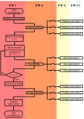
A model simulation of a typical base model/MESSy setup can be subdivided into
10
three phases (initialization phase, time integration phase, finalizing phase), as shown by a simplified flow chart in Fig.5.
The main control (time integration and run control) is hosted by the base model, and therefore the base model is also responsible for the flow of the three phases. After the initialization of the base model, the MESSy infrastructure (i.e. the generic
15
submodels) is initialized. At this stage the decision is made which submodels are switched on/off. Next, the active MESSy submodels are initialized sequentially. This initialization is split into two parts (not explicitely shown in Fig. 5). First, the internal setup of all active submodels is initialized, and second the potential coupling between all active submodels is performed (see Appendix B). After the initialization phase the
20
time integration (time loop) starts, which is controlled by the base model. All MESSy submodels are integrated sequentially according to the operator splitting concept (see Fig. 3). At the end of the time integration, the MESSy submodels and the MESSy infrastructure are finalized before the base model terminates.
The four layer MESSy-interface structure as presented here can be applied to a
vari-25
ety of different model types with respect to the dimension (e.g.. 0-D=box, 1-D=column, 2-D, 3-D), the domain (e.g. global, regional, ocean, atmosphere, land), and then allows the straightforward exchange of processes (i.e. of the submodels in the SMCL). This is shown next.
ACPD
4, 7139–7166, 2004The Modular Earth Submodel System P. J ¨ockel et al. Title Page Abstract Introduction Conclusions References Tables Figures J I J I Back Close Full Screen / Esc
Print Version Interactive Discussion
© EGU 2004 4. Application
4.1. Box models as the base model
Although most submodels are mainly written for the eventual inclusion into larger re-gional and global models (e.g. GCMs), the MESSy structure supports and also en-courages their connection to a box model, whereby “box model” is defined here as
5
the smallest meaningful entity for a certain process which is running independently of the comprehensive ESM. We have applied the MESSy structure to miscellaneous box models of which two examples are presented.
As a first example, Fig. 6 shows how an atmospheric chemistry submodel can be connected to either a simple box model (here a 0-D model in the classical sense), or
10
to a complex GCM. It is important to note that exactly the same files of the chemistry submodel are used in both cases. Therefore, box models are an ideal environment for debugging and validating a submodel. While developing the submodel, it can be tested in fast box model runs without the need for expensive global model simulations. Once the submodel performs well, it can directly be included into the GCM without any
15
further changes. A detailed description of the MESSy submodel MECCA (Module for Efficiently Calculating the Chemistry of the Atmosphere) can be found in the companion article Sander et al. (2004).
A second useful example for a box-model is the re-discretization tool NCREGRID. NCREGRID allows the transformation of 2D and 3D gridded geo-data between
arbi-20
trary resolutions. A more detailed description of NCREGRID will be published else-where (J ¨ockel, 2004, manuscript in preparation). The same code which is used for the box-model (i.e. the “offline” re-discretization tool NCREGRID) is used in the GCM/ESM as data import interface (which is coded as a generic submodel, see Appendix A) for the import of initial and boundary conditions in arbitrary resolutions.
ACPD
4, 7139–7166, 2004The Modular Earth Submodel System P. J ¨ockel et al. Title Page Abstract Introduction Conclusions References Tables Figures J I J I Back Close Full Screen / Esc
Print Version Interactive Discussion
© EGU 2004
4.2. GCM as the base model
The MESSy interface has also been successfully implemented into the general circu-lation model ECHAM5 (Roeckner et al., The atmospheric general circucircu-lation model ECHAM 5. PART I: Model description, MPI-Report, 349, 2003 (http://www.mpimet.
mpg.de/en/extra/models/echam/mpi report 349.pdf)), thus extending it into a fully
cou-5
pled chemistry-climate model. In the electronic supplement (http://www.copernicus.
org/EGU/acp/acpd/4/7139/acpd-4-7139-sp.zip) details about the specific implementa-tion can be found. This provides exciting new possibilities to study feedback mech-anisms. Examples include stratosphere-troposphere coupling, atmosphere-biosphere interactions, multi-component aerosol processes, and chemistry-climate interactions.
10
MESSy also provides an important tool for model inter-comparisons and process studies. As an example, aerosol-climate interactions could be investigated in two model runs in which two different aerosol submodels are switched on. For processes without feedbacks to the base model, it is even possible to run several submodels for the same process simultaneously. For example, the results of two photolysis schemes could be
15
compared while ensuring that they both receive exactly the same meteorological and physical input from the GCM.
4.3. MESSy submodels
A complete and up to date list of submodels can be found at the MESSy web-site athttp://www.messy-interface.org. Detailed description, validation, and application of
20
each submodel will be published elsewhere. 4.4. Future developments
MESSy is an activity that is open to the scientific community following the “open source” philosophy. We encourage collaborations with colleague modelers, and aim to e ffi-ciently achieve improvements. The code is available at no charge. For details, we refer
ACPD
4, 7139–7166, 2004The Modular Earth Submodel System P. J ¨ockel et al. Title Page Abstract Introduction Conclusions References Tables Figures J I J I Back Close Full Screen / Esc
Print Version Interactive Discussion
© EGU 2004
to the web-sitehttp://www.messy-interface.org.
Additional submodels and other contributions from the modeling community will be highly appreciated. We encourage modelers to adapt their code according to the MESSy-standard.
5. Conclusions 5
The transition from General Circulation Models to Earth System Models requires the development of new software technologies and a new software management, since the rapidly increasing model complexity needs a transparent control. The Modular Earth Submodel System (MESSy) provides a generalized interface structure, which allows unique new possibilities to study feedback mechanisms between various
bio-10
geo-chemical processes. Strict compliance with the ISO-Fortran95 standard makes it highly portable to different hardware platforms. The modularization allows for uncom-plicated connection to various base models, as well as the co-existence of different algorithms and parameterizations for the same process, e.g. for testing purposes, sen-sitivity studies, or process studies. The coding standard provides a multi-developer
15
environment, and the flexibility enables a large number of applications with different foci in many research topics referring to a wide range of temporal and spatial scales.
We look forward to receiving interesting contributions from the geosciences modeling community.
Appendix A: The MESSy infrastructure (generic submodels) 20
The BMIL (Fig.4) comprises the MESSy infrastructure as described in Sect.3. This in-frastructure is itself coded in the form of generic submodels, i.e. separated into a base model independent part (generic SMCL) and a base model dependent part (generic SMIL). Currently, the MESSy implementation provides the following generic submod-els:
ACPD
4, 7139--7166, 2004
The Modular Earth Submodel System P. J¨ockel et al. Title Page Abstract Introduction Conclusions References Tables Figures J I J I Back Close Full Screen / Esc
Print Version Interactive Discussion
© EGU 2004 – central submodel control interface
– main switch: standard user interface for switching the submodels on/off (one global switch per submodel)
– main control: provides generalized main entry points for triggering the sub-models from the base model
5
– data transfer/export interface
– main tracer: handling of chemical species and their individual properties – main data: data exchange between base model and submodels in both
di-rections
– main constants: physical constants and machine precision parameters 10
– data import interface
– ncregrid: grid independent input from netCDF files (see http://my.unidata.
ucar.edu/content/software/netcdf/index.html for the netCDF format; more in-formation on ncregrid will be published elsewhere (J ¨ockel, manuscript in
preparation, 2004)).
15
– main tools: common tools shared by several submodels
Appendix B: The MESSy user interface
The MESSy user interface is implemented using Fortran95 namelist constructs. User interaction is required at three stages (in the following<submodel>denotes the unique name of a submodel):
20
1. The run scriptxmessy is controlling the comprehensive model setup. Here, the user selects the submodels to be used for the model run. There is one global
ACPD
4, 7139–7166, 2004The Modular Earth Submodel System P. J ¨ockel et al. Title Page Abstract Introduction Conclusions References Tables Figures J I J I Back Close Full Screen / Esc
Print Version Interactive Discussion
© EGU 2004
switch per submodel for activating it (USE_<submodel>=T), or deactivating it
(USE_<submodel>=F), with the default being ’deactivated’. The run script writes
the Fortran95 namelist file MESSy.nml, which contains all submodel switches. This namelist file is read by the executable during the MESSy-initialization (cen-tral submodel management interface, generic submodel main switch, see Figs.4 5
and5). Furthermore, the user specifies in the run script which namelist files (e.g., containing predefined setups) should be used to control a specific submodel:
NML_<submodel>=... NML_<submodel>_T=...
The chosen namelist files are copied by the run script into the files
10
<submodel>.nmland<submodel>_t.nml, respectively, which are the default
user interface for a specific submodel.
2. The namelist-file<submodel>_t.nmlcontains the namelists for the data import interface for initialization of chemical compounds (= tracers) during the initializa-tion phase of the model run.
15
3. The namelist-file<submodel>.nmlcontains the namelists for the submodel op-eration:
– The CTRL-namelist contains all parameters/switches affecting the internal complexity and flow control of a specific submodel (control interface).
– TheCPL-namelist contains all parameters/switches affecting the coupling of
20
a specific submodel to the base model and to other submodels (coupling interface).
– Additional namelists control the data import interface, e.g. for importing time varying boundary conditions at dedicated steps during the time integration phase.
ACPD
4, 7139--7166, 2004
The Modular Earth Submodel System P. J¨ockel et al. Title Page Abstract Introduction Conclusions References Tables Figures J I J I Back Close Full Screen / Esc
Print Version Interactive Discussion
© EGU 2004 – In case the submodel hosts one or more sub-submodels, the namelists
for control and coupling of a specific sub-submodel (here with
name <sub-submodel>) are called CTRL_<sub-submodel> and
CPL_<sub-submodel>, respectively.
Appendix C: The MESSy directory structure 5
All MESSy related files are located in the./messysubdirectory tree of the base model distribution:
– src: contains the core modules (SMCL files) of the submodels
– <smil>: contains the base model dependent submodel interface modules (SMIL
files), whereby<smil>is an appropriate name identifying the used base model
10
– lib: contains the MESSy-library after successful compilation – box: contains the source code of the box models (see Sect.4.1)
– bin: contains the executables of the MESSy-box models after successful compi-lation
– nml: contains the namelist-files (user interface)
15
– util: contains utility scripts
The MESSy core modules (SMCL, inmessy/src) will be compiled and archived as the librarylibmessy.a. The MESSy interface modules (SMIL, inmessy/<smil>will be compiled and linked with the base model code.
ACPD
4, 7139–7166, 2004The Modular Earth Submodel System P. J ¨ockel et al. Title Page Abstract Introduction Conclusions References Tables Figures J I J I Back Close Full Screen / Esc
Print Version Interactive Discussion
© EGU 2004 Appendix D: The MESSy coding standard
For the implementation of the MESSy interface, all changes to the base model are coded with “keyhole surgery”. This means that changes to the base model are only allowed if they are really needed, and if they are as small as possible. Changes to the base model code are encapsulated in preprocessor directives:
5
#ifndef MESSY <original code> # else
<changed code for MESSy> #endif
10
Likewise, additional code is encapsulated as
#ifdef MESSY
<new MESSy code> #endif
Overall, code development follows the following rules:
15
– Each process is represented by a separate submodel. – Every submodel has a unique name.
– A submodel is per default switched OFF and does nothing unless it has been switched on (USE_<submodel>=T) by the user via a unique namelist switch in the run scriptxmessy(see Appendix B).
20
– Several submodels for the same process (e.g. different parameterizations) can coexist.
– MESSy modules are Fortran95-standard conform (ISO/IEC-1539-1). This can, for example, be checked using the Fortran analyzer “forcheck” (see http://www.
forcheck.nl).
ACPD
4, 7139–7166, 2004The Modular Earth Submodel System P. J ¨ockel et al. Title Page Abstract Introduction Conclusions References Tables Figures J I J I Back Close Full Screen / Esc
Print Version Interactive Discussion
© EGU 2004 – Each submodel consists of two modules (two layers):
1. submodel core layer (SMCL): A completely self-consistent, base model in-dependent Fortran95 core-module to/from which all required quantities are passed via parameters of its subroutines. Self-consistent means that there are neither direct connections to the base model, nor to other
submod-5
els. The core-module providesPUBLICsubroutines which are called by the interface-module, andPRIVATEsubroutines which are called internally. 2. submodel interface layer (SMIL): An interface-module which organizes the
calls and the data exchange between submodel and base model. Data from the base model is preferably accessed via the generic submodel SMIL
10
“main data”. The interface module provides a set of PUBLIC subroutines which constitute the main entry-points called from the MESSy central sub-model control interface.
– The core module must be written to run as the smallest possible entity (e.g. box, column, column-vector (2-D), global) on one CPU in a parallel environment (e.g.
15
MPI). Therefore,STOP-statements must be omitted and replaced by a status flag
(INTENT(OUT)) which is 0, if no error occurs. In the same way, WRITE- and
PRINT-statements must only occur in the part of the code which is exclusively
executed by a dedicated I/O processor. This is controlled in the SMIL.
– Data transfer between submodels is performed exclusively via the generic sub-20
model “main data” within the interface layer. DirectUSE-statements to other sub-models are not allowed.
– The internal application flow of a submodel is controlled by switches and parame-ters in theCTRL-namelist; coupling to the base model and/or other submodels is defined via switches and parameters in theCPL-namelist (see Appendix B).
25
– If the complexity of a submodel requires separation into two or more files per layer (core or interface), shared type-, variable- and parameter-declarations can
ACPD
4, 7139–7166, 2004The Modular Earth Submodel System P. J ¨ockel et al. Title Page Abstract Introduction Conclusions References Tables Figures J I J I Back Close Full Screen / Esc
Print Version Interactive Discussion
© EGU 2004
be located in*_mem.f90files (or*_mem_<smil>.f90files, respectively) which can be USEd by the submodel files within the respective layer. These memory-modules must be used by more than 1 file within the relevant layer, and must not contain any subroutine and/or function.
– The filename of each MESSy file identifies submodel, layer, and type: 5
messy_<submodel>[_<subsubmodel>][_mem][_<smil>].f90
where [...] means “optional”, <...> means a specific name, mem indicates memory-files, and <smil> the interface layer modules. Each MESSy module must have the same name as the file it resides in, however with the suffix.f90
removed. All MESSy files start with ’messy_’.
10
– MESSy-submodels are independent of the specific base model resolution in space and time. If this is not possible (e.g., for specific parameterizations) or not yet implemented, the submodel needs to terminate the model in a controlled way (via the status flag), if the required resolution has not been chosen by the user.
15
– A submodel can host sub-submodels, e.g. for different various parameterizations, sub-processes, etc. The namelists of the respective sub-submodel are named according to Appendix B.
– The smallest entities of a submodel, i.e. the subroutines and functions, must be as self-consistent as possible according to:
20
– USE-statements specific for a certain subroutine or function must be placed where the USEd objects are needed, not into the declaration section of the module.
– IMPLICIT NONEis used for all modules, subroutines and functions.
– If a function or subroutine provides an internal consistency check, the result 25
must be returned via anINTEGERparameter (status flag), which is 0, if no error occurs, and identifies the problem otherwise.
ACPD
4, 7139–7166, 2004The Modular Earth Submodel System P. J ¨ockel et al. Title Page Abstract Introduction Conclusions References Tables Figures J I J I Back Close Full Screen / Esc
Print Version Interactive Discussion
© EGU 2004
– PRIVATE must be the default for every module, with the exception of
memory-files. ThePUBLICattribute must explicitely used only for those subroutines, func-tions, and variables that must be available outside of the module.
– Variables must be defined (not only declared!). The best way to define a variable is within its declaration line, e.g.:
5
INTEGER :: n = 0
– Pointers need to be nullified, otherwise, the pointer’s association status will be initially undefined. Pointers with undefined association status tend to cause trou-ble. According to the Fortran95 standard even the test of the association status with the intrinsic functionASSOCIATEDis not allowed. Nullification of a pointer is
10
preferably performed at the declaration
REAL, DIMENSION(:,:), POINTER :: & ptr => NULL()
or at the beginning of the instruction block with
NULLIFY(ptr)
15
– Wherever possible,ELEMENTALand/orPURE functions and subroutines must be used.
– Numeric precision is controlled within the code by specifying the KIND param-eters. Compiler switches to select the numeric precision (e.g. “-r8”) must be avoided.
20
– Since the dependencies for the build-process are generated automatically, obso-lete, backup- or test-files must not have the suffix.f90. Instead, they must be renamed to*.f90-bakor something similar.
– Any USE command must be combined with an ONLY statement. This makes it easier to locate the origin of non-local variables. (Exception: A MESSy-core
mod-25
ACPD
4, 7139–7166, 2004The Modular Earth Submodel System P. J ¨ockel et al. Title Page Abstract Introduction Conclusions References Tables Figures J I J I Back Close Full Screen / Esc
Print Version Interactive Discussion
© EGU 2004 Acknowledgements. The authors thank the following people for supporting the MESSy
stan-dard, for adapting various submodels to it, and for contributing to specific submodels: S. Brinkop (DLR), C. Br ¨uhl (MPI-C), J. Buchholz (MPI-C), M. de Reus (MPI-C), G. Erhardt (DLR), L. Ganzeveld (MPI-C), L. Grenfell (FUB), V. Grewe (DLR), A. Kerkweg (MPI-C), I. Kirchner (FUB), C. Kurz (DLR), S. Metzger (MPI-C), M. Ponater (DLR), A. Pozzer (MPI-C), A. Rhodin 5
(DWD), R. Sausen (DLR), B. Steil (MPI-C), M. Tanarhte (MPI-C), H. Tost (MPI-C), M. Traub (MPI-C), J. van Aardenne (MPI-C), R. von Glasow (UHD), R. von Kuhlmann (MPI-C). (DLR= Deutsches Zentrum f ¨ur Luft- und Raumfahrt= German Aerospace Center, DWD = Deutscher Wetterdienst= German Weather Service, MPI-C = Max Planck Institute for Chemistry, UHD = University of Heidelberg, FUB= University of Berlin). Support from the Max Planck Computer 10
Center in Garching (RZG) is gratefully acknowledged.
References
Sander, R., Kerkweg, A., J ¨ockel, P., and Lelieveld, J.: Technical Note: The new comprehensive atmospheric chemistry module MECCA, Atmos. Chem. Phys. Disc., in press, 2004.
ACPD
4, 7139–7166, 2004The Modular Earth Submodel System P. J ¨ockel et al. Title Page Abstract Introduction Conclusions References Tables Figures J I J I Back Close Full Screen / Esc
Print Version Interactive Discussion
© EGU 2004
advectionradiationchemistry microphysics convection dynamics chemistry biology ...
vegetationlandusesoil ... Atmosphere Ocean coupler ... ... Landsurface
Fig. 1. Domain-oriented approach for building an ESM from existing domain specific models
(atmosphere, ocean, land surface, ...). Data exchange can be controlled from each domain model and organized via a universal coupler. The domain models and the coupler are self-contained executables running simultaneously; communication is performed via the coupler.
ACPD
4, 7139–7166, 2004The Modular Earth Submodel System P. J ¨ockel et al. Title Page Abstract Introduction Conclusions References Tables Figures J I J I Back Close Full Screen / Esc
Print Version Interactive Discussion © EGU 2004
advection
radiation
chemistry
microphysics
convection
...
clock/run-control
(base model)
standard interface
soil
vegetation
land use
...
dynamics
biology
chemistry
...
...
Atmosphere
Ocean
Land surface
...
MESSy
Fig. 2. Process-oriented approach to establish an ESM. Each physical process is coded as a
modular entity connected via a standard interface to a common base model. The base model can be for instance an atmosphere or ocean GCM, etc. At the final development state, the base model contains hardly more than a central clock and a run control for all modularized processes. All processes and the base model together form one comprehensive executable. Via the standard interface, data exchange between all processes is possible.
ACPD
4, 7139–7166, 2004The Modular Earth Submodel System P. J ¨ockel et al. Title Page Abstract Introduction Conclusions References Tables Figures J I J I Back Close Full Screen / Esc
Print Version Interactive Discussion © EGU 2004 X(t-1) ðX/ðt OP 1 + + OP 2 + + OP n + +
...
time integration 0Fig. 3. Operator splitting time integration scheme (in this case a second order scheme used
in many GCMs). Each process is represented by an operator (OP 1, OP 2, . . . , OP n) which calculates a tendency (∂X/∂t) for the quantity X based on the quantity X at the time step before (t − 1) and the sum of all tendencies calculated by the operators in the sequence before.
ACPD
4, 7139–7166, 2004The Modular Earth Submodel System P. J ¨ockel et al. Title Page Abstract Introduction Conclusions References Tables Figures J I J I Back Close Full Screen / Esc
Print Version Interactive Discussion © EGU 2004 BASE MODEL (GCM) central submodel management interface SUBMODEL INTERFACE SUBMODEL CORE (PHYSICS, CHEM, ...) (BASE MODEL INDEPENDENT !!!)
NCREGRID COUPLING TRANSPORT GRID TIME CONTROL (EVENTS)
DATA TRANSFER VIA PARAMETER LIST CALL D A T A T R A N SF E R B E T W E E N SU B M O D E L S A N D T O /F R O M T H E B A SE M O D E L SP E C IE S SH A R E D B E T W E E N SU B M O D E L S C A L L SU B M O D E L GLOBAL SWITCH TRACER INITIALIZATION NON-TRACER DATA IMPORT D A T A I M PO R T C A L L S T A N D A R D SU B R O U T IN E S B M L B M IL SM IL SM C L data transfer/export
interface tracer data importinterface
netCDF-data CONTROL OF INTERNAL COMPLEXITY C A L L S T A N D A R D SU B R O U T IN E S us er in te rf ac e ST A N D A R D N A M E L IS T C O N T R O L
ACPD
4, 7139–7166, 2004The Modular Earth Submodel System P. J ¨ockel et al. Title Page Abstract Introduction Conclusions References Tables Figures J I J I Back Close Full Screen / Esc
Print Version Interactive Discussion © EGU 2004 Start of model run End of model run Initialize submodel 1 Initialize base model
Initialize MESSy B M L B M IL S M IL Initialize submodel 2 Initialize submodel 3 Run submodel 1 Basic physical and meteorological calculations (p, T, rh,...)
Run MESSy Run submodel 2 Run submodel 3
Finalize submodel 1
Finalize base model
Finalize MESSy Finalize submodel 2 Finalize submodel 3 Start of time loop
t = t0
t = tend ? Yes No
end of time loop
S M C L
Fig. 5. Idealized flow chart of a typical MESSy setup (see text for details) consisting of three
submodels connected to the base model via the MESSy interface. The model simulation can be subdivided into three phases: initialization phase, time integration phase, finalizing phase.
ACPD
4, 7139–7166, 2004The Modular Earth Submodel System P. J ¨ockel et al. Title Page Abstract Introduction Conclusions References Tables Figures J I J I Back Close Full Screen / Esc
Print Version Interactive Discussion © EGU 2004 Interface GCM Aerosol Submodel Interface Boxmodel
(insert here) (insert here) ... other
submodels
Atmospheric Chemistry Submodel
Fig. 6. A MESSy submodel (here an example for atmospheric chemistry integrations) can be