HAL Id: hal-01661112
https://hal.uca.fr/hal-01661112
Submitted on 11 Dec 2017
HAL is a multi-disciplinary open access
archive for the deposit and dissemination of
sci-entific research documents, whether they are
pub-lished or not. The documents may come from
teaching and research institutions in France or
abroad, or from public or private research centers.
L’archive ouverte pluridisciplinaire HAL, est
destinée au dépôt et à la diffusion de documents
scientifiques de niveau recherche, publiés ou non,
émanant des établissements d’enseignement et de
recherche français ou étrangers, des laboratoires
publics ou privés.
Robust Discovery, Addressing and Routing Protocol for
Dynamic Linear Network
Moussa Sarr, François Delobel, Michel Misson, Ibrahima Niang
To cite this version:
Moussa Sarr, François Delobel, Michel Misson, Ibrahima Niang. Robust Discovery, Addressing and
Routing Protocol for Dynamic Linear Network. International Symposium Wireless Communication
Systems (ISWCS), Aug 2017, Bologna, Italy.
pp.140-145, �10.1109/ISWCS.2017.8108099�.
�hal-01661112�
Robust Discovery, Addressing and Routing Protocol
for Dynamic Linear Network
Moussa D´ethi´e Sarr
∗, Franc¸ois Delobel
∗, Michel Misson
∗and Ibrahima Niang
†∗Clermont Universit´e / LIMOS CNRS - Complexe scientifique des C´ezeaux, 63172 Aubi`ere cedex, France
Emails:{sarr,delobel,misson}@sancy.clermont-universite.fr
†Laboratoire d’Informatique, Universit´e Cheikh Anta Diop de Dakar (UCAD), B.P. 5005 Dakar-Fann, S´en´egal
Email: [email protected]
Abstract—Linear Wireless Sensor Networks (LWSN) are a sub-case of Wireless Sensor Networks where nodes are roughly located through multiple lines. They can be used to monitor many real-life infrastructure –e.g. roads, pipelines– or natural entities such as rivers. Classical network solutions are mostly inefficient on LWSN because these topologies –a tree with very long branches– are often a worst-case scenario of many protocols. Therefore few specific protocols have been designed for LWSN. But most of them require manual configuration of the nodes and are static. Real-life conditions require the network to adapt to changing situations –addition of new nodes or sets of nodes, node destruction– or to solve problems of data congestion.
We propose a new network protocol called Dynamic Disco-Proto covering the setting up of the logical topology, address distribution without spoilage, dynamic addition of nodes or branches, and even dynamic addition of new data sinks. All these operations happen without human interaction or knowledge of the topology. Our proposition keeps the benefits of a mainly hierarchical routing without paying the price of address spoilage which can be the aftermath of mainly linear topologies.
We evaluate our Dynamic DiscoProto protocol for LWSN using Castalia simulator and demonstrate that it resolves the problem of orphan nodes during network setup and also has good performance for dynamic and large LWSN. Eventually, simulation results demonstrate that our proposition adapts to multi-Sink deployment and improves data packet delivery ratio and data packet latency.
Keywords—Linear Wireless Sensor Networks, LWSN, Address-ing, RoutAddress-ing, Automatic Deployment, ClusterAddress-ing, Multi Sinks
I. INTRODUCTION
Linear Wireless Sensor Networks (LWSN) [1], [2], [3], [4] are built by deploying nodes in several portions of lines to monitor applications such as river, pipeline, railways [5], bridge structure [6]). LWSN physical topologies are character-ized by a low number of neighbors for each node and high distance from the sink. Each node has to be used not only as a sensor but also as a relay. The logical topology is a peculiar and highly unbalanced tree, with high depth, small average number of children per node, a majority of nodes with only a single child. Linear topologies are the worst cases for hierar-chical networks (spoilage) and for stochastic distribution (time for reparation). Therefore, a direct transposition of classical protocols on LWSN is not efficient.
[4] proposes a mechanism called DiscoProto well-suited for network formation, addressing, routing in Linear Wireless Sensor Networks. It allows automatic construction of the
network and avoids address spoilage. But it has two main draw-backs: it relies on a single sink and does not allow dynamic addition or destruction of nodes to the network. LWSN are specially sensitive to end-to-end delay and congestion because they have very few paths that lead to the sink. The obvious solution is to dynamically add new sinks when high congestion or long paths are detected. Adding new sinks is not compatible with the hierarchical addressing used in Discoproto.
Moreover, all the structures which can be monitored are subject to change: a new road may be built on a monitored infrastructure, a tributary of a monitored river may be detected as carrying pollution and also equipped with wireless sensors. A LWSN protocol has to be able to welcome not only single nodes, but also whole sets of nodes. Hierarchical addressing allows efficient routing but addition in an unbalanced tree often leads to network reconstruction or orphan nodes. We introduce Dynamic Discoproto protocol to dynamically add not only several sparse nodes or whole branches of nodes to an already deployed network but also secondary sinks to ease data collec-tion. Dynamic Discoproto ensures reliability of LWSN (mostly Linear Wireless Sensors Network) in harsh environments and preserves the coherency of existing hierarchical addressing and the benefits of hierarchical routing.
Routing in the original DiscoProto is hierarchical and does not directly allow multisink. We therefore propose with Dynamic Discoproto a mechanism for sink selection based on distance. When a sink is selected, routing will use the mainly hierarchical routing tables. Multiple sinks allow Dy-namic Discoprototo balance the network traffic, to reduce data congestion and end-to-end delay, and packet loss.
The paper is organized as follows. DiscoProto protocol and related works in addressing mechanism and Multi-Sink routing in WSN are presented in section II. In section III, we introduce a dynamic version of DiscoProto named Dy-namic DiscoProto. In section IV, we describe a multi-sink selection mechanism for Dynamic DiscoProto. The simulation and performance evaluation of our proposition are presented in section V. Section VI concludes the paper and presents possible extensions of our work.
II. STATE OF THE ART
A. Automatic Discovery of Topology and Addressing for Lin-ear WSN
In [4], the authors propose a discovery and network forma-tion protocol called DiscoProto, well suited for LWSN where
nodes are deployed in several portions of lines. DiscoProto generates a logical topology similar to a physical topology deployed without knowledge of network parameters: maximum depth, maximum number of children by node, position of the node. DiscoProto also attributes addresses so that hierarchical routing is possible but without wasting address space. Based on the objective value in Equation 1, it constructs connected LWSN closeness to the physical topology.
offer(c, u)=α × Common(c, u) − Sons(c)
− β × SumNeighbors(c, u) (1) withα = 10 and β = 10001 .
After a network setup, DiscoProto allows a hierarchical address distribution based on the exact number of connected nodes in the linear WSN. The PAN coordinator computes and propagates an appropriate address block, based on Equation (2), to its son nodes using a PropaAddr message.
addrBlockend =
n
X
i=1
Size(i) × (F skip + 1) (2)
Each connected node receiving an address block [a, b], keeps a as its own address. Then, it keeps address block [a+1, a+F skip] as available addresses for future associations and the remaining interval[a+F skip+1, b] is divided between its sons proportionally to the size of their subtree. F skip is the coefficient of address availability.
To ensure efficient hierarchical routing without exchanging control routing messages, nodes forwarding an PropaAddr add a new entry in their routing tables. DiscoProto offers mech-anism for dynamic node removal but not for dynamic node addition: a network has to be rebuilt. Moreover, it assumes that only one sink exists and plays the role of coordinator of the network.
B. Distributed Borrowing Addressing Scheme for Zig-Bee/IEEE 802.15.4 Wireless Sensor Networks
In [7], authors propose a Distributed Borrowing Addressing (DIBA) mechanism to solve association failure in distributed address assignment mechanism used in ZigBee. All router nodes in this network broadcast beacon frames including the Available Address Count (AAC), which is the number of children that the routers can add. A new node joining the network chooses the parent node which has the biggestAAC. However, if the parent node has no available address or if its tree depth is Lm, it uses address borrowing mechanism to obtain an address for these new nodes. When a parent node receives an Association Request from new node and has reached the limit of Cm, it broadcasts an Address Borrowing Requestto borrow addresses from its neighbor nodes. Some of them respond with an Address Borrowing Response including Available Address (AA) and AAC. A node that sends a request chooses an AAs with biggest AAC. If multiple nodes with same AAC are found, P selects a node with the highest AA. The neighbor node LN (Lender Node) that has received a request message calculates by the following function (see
Equation (3)) an appropriateAA to lend, where num BA is the number of address borrowed.
AA = AddrLN+ (Rm − num BA) × Cskip(d) + 1 (3)
Ifnum BA < Rm
If an incoming node receives an available address for lending (called AAL) of another node, it reserves also the address block [AAL, AAL + Cskip(d) − 1].
C. Address Assignment and Routing Schemes for ZigBee-Based Long-Thin WSN
In [8], the authors consider a special case of ZigBee cluster-tree where each cluster is composed of nodes deployed on line segment. Each cluster is delimited by a cluster head and a cluster bridge. For the node address assignment, the authors divide the 16-bit network address in two parts: 16 − m bits for the Cluster ID (CID) andm bits for Node ID (NID). After the manual planning of logical network where each cluster in a physical network is represented by a node in a logical topology, authors attribute CID to each cluster according to the Equation in 4. After a CID assignment, cluster heads incrementally assign NID to each node in a cluster by initial by setting its NID to 0.
CIDChild= CIDP arent+ (n − 1) × CCskip(d) + 1,
ifCCm >= 2 (4) whereCskip(d) = 1−CCmCLm−d
1−CCm
This approach suffers the same limitations as DAAM: The maximum number of clusters that can be addressed is 2m
and the maximum addressable node is 2(16−m). In addition
the network depth CLm is limited by a chosen parameter m. Finally, the head and bridge of each cluster have to be manually selected during the network deployment. Therefore, human intervention is also necessary to elect another node as cluster-head or bridge when one of these nodes fails. This manual selection method of cluster-head or new bridge causes a network partitioning. In fact, all traffic of clusters is routed by a cluster-head to bridge node of its parent cluster.
D. Multi-Sink routing protocols in WSNs
Several protocols are proposed for multi-sink routing in WSNs to solve problems like network overload or energy exhaustion. They aim to maximize network lifetime by sav-ing energy of network nodes and to minimize number of transmissions and packet failures. To construct the path from the node to the sink, most of these protocols [9], [10], [11], [12] use different metrics such as hop count, hop downstream neighbors, energy consumption level, neighbor buffer capacity, end-to-end energy level.
In [11], authors propose a generic energy-Balancing gradient-based routing protocol (GB-GBR) where each node constructs different gradients of multiple sinks based on the remaining average energy (AvgREk) of the path, the estimate
energy consumption (∆En) on the node and the number of hops (N hopsk). Each node forwards data packet to the sink
In [12], authors propose another gradient-based protocol called GLOBAL (Gradient-based routing protocol for LOad-BALancing), using a flooding-based gradient algorithm to construct gradient for each node and provide an optimal path to forward data to a sink based on cumulative residual energy depletion rate (REDR) which represents a measure of the traffic load on a sensor node. In GLOBAL the construction of the gradient is based on the broadcast of an advertisement message ADV containing :
1) Number of hops;
2) Sum of REDR of nodes traversed by the ADV; 3) Maximum REDR value among REDR values of nodes
traversed by the ADV
The drawback of these protocols is that they are based on average or sums of given costs on the path from the node to the sink to select the best route. This approach does not allow detecting weak nodes, exhausted nodes or overloaded links because they are based on flooding approach to construct gradient. In Linear environment, each node has one or two neighbors in the upstream to the sink and the same downstream. The Broadcast of routing advertisements increases overload and is not well suited for Linear WSNs: there is no need to flood the whole network as nodes in a subtree cannot be used to reach the sink. On the other hand, the choice of best link to the sink at every hop proposed in [11], [12], can generate infinite loops in linear WSNs and increase the packet loss rate and the energy exhaustion of nodes in the loop.
III. DYNAMICDISCOPROTO
After a network setup, Dynamic Disco Proto allows new spare nodes (new sink nodes or network nodes ) or new whole branches (set of nodes physically organized in roughly linear shape) to join an existing formed linear WSN where all connected nodes have their own address block. Dynamic Disco Proto can be described by the following mechanisms. A. Network Join Procedure
To join the network, new nodes start to broadcast HELLO messages. Connected nodes in a neighborhood answer with another HELLO messages. HELLO messages contain neigh-borhood information and are used to update table of neighbors. After the HELLO period, connected nodes select a node with best Of f er (association link cost), similarly to the original mechanism described in [4]. At the end of the Son Collection step, connected nodes start the address distribution phase based on size of new child nodes:
1) If the node with address a has enough available addresses (i.e. numN ewSon ≤ F skip) then it at-tributes the address a + nbrN ewSon to the Propa-Sons message sender node where nbrN ewSon is the number of new connected sons after the network setup.
2) Otherwise, the node performs an address block real-locationstep in the following section III-B.
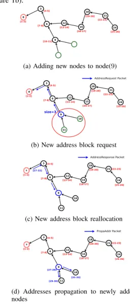
Figure 1 shows an example of join procedure where a branch of four nodes is added to an existing network. In Figure 1a, new nodes and connected nodes in their neighborhood
exchange HELLO message in order to update their neighbor table. After this discovery phase, only connected nodes 3 and 18 that receive HELLO messages, start a collection son process (see Figure 1b).
(a) Adding new nodes to node(9)
(b) New address block request
(c) New address block reallocation
(d) Addresses propagation to newly added nodes
Figure 2: Addresses reallocation procedure
B. Addresses block reallocation and influence on routing When a node needs more available addresses than the spare ones, it requests a block of addresses from the coordinator node (the sink in the case of a unique-sink network) whose size is proportional to the number of new nodes (see Section II-A). This allocation of spare address block will reduce the number of future address reallocation.
Address exhaustion can be caused by any of the following conditions :
• Connected nodes have distributed all available ad-dresses to new nodes or branches (example figure 2b: Node 9 has given 2 spare addresses to 10 and 11 and requests new addresses),
• Connected nodes have not enough available addresses for new branches that need to join a network.
(a) Add new branch of nodes (b) Add new branch of nodes (c) Subtree size collection
(d) New address block request (e) New address block reallocation (f) Addresses propagation to newly added nodes
Figure 1: new branch join procedure A connected father node needing addresses to distribute
sends a AddressRequest message to the coordinator includ-ing nbrN ewSon + 1. The coordinator computes a new ad-dress block [oldEndBlock + 1, oldEndBlock + F skip × (nbrN ewSon + 1) + 1] and answers with AddressResponse message.
Figure 2 shows an example of new address block realloca-tion when two spare nodes are associated with node 9.
When the requester node 9 receives a new address block [27, 32] from the coordinator (Figure 2c), it keeps address block[27, 28] as free addresses for future associations and remaining address blocks are dispatched between their newly added sons proportionally to their subtree size using PropaAddr (Figure 2d).
In Figure 1, we show another example address block reallocation for a new branch of four nodes. When node 3 receives the size of new branch4, it sends an address request to the PAN coordinator which answers by an Address Response containing the block [33, 44].
In order to maintain hierarchical routing, nodes forwarding an AddressResponse add a new entry in their routing tables. This entry containsstartBlock, endBlock and the destination node of the AddressResponse (see Table I).
startBlock endBlock addrNode
9 11 9
12 26 12
27 32 9
Table I: Routing table of node6 in Figure 2d
IV. MULTISINKROUTING INLWSNS
Multi Sink Routing Protocolis an adaptation of hierarchical routing protocol described in II-A. We assume that all the
nodes in the network have a parent node and a unique hierarchical address.
A. Path construction
After a network setup, each sink node sends a sink ad-vertisement message (SADVERT) to its sons nodes which propagate it (see Figure 3). A SADVERT from a sink should not be forwarded by another sink so flooding the whole network is avoided.
Figure 3: SADVERT propagation on Network with two sinks
Each node receives at least a SADVERT message from a sink (either from the main sink (PAN coordinator) or from another sink only separated by nodes). SADVERT contains the sink address, a hopCount and nextHop fields. A node forwarding a SADVERT increments hopCount and stores its address in SADVERT Table (see Table II). When a node receives a SADVERT, if the source address of SADVERT does not exist in a SADVERT table, it stores the address of sink, the address of next hop node, and the hop count. Otherwise, the node updates values if hop count of received SADVERT is smaller than the current in the table.
Periodically the node chooses the sink with the smallest hop count as current sink and the data transmission can be sent to the current sink. When a node receives data messages, it forwards it according to the next hop node for the current sink.
B. Route Maintenance
During a network lifetime, sink nodes periodically send an SADVERT through the network. We add a time stamp field to different entries in a SADVERT table (See Table II). Thus, a node that does not receive SADVERT during expire time can not update the sink entry in the SADVERT table and deletes the entry.
sinkAddr nextHop hopCount ExpireTime (msec)
0 3 2 631
16 12 3 263
Table II: SADVERT table with expire time of node6 If the sink for deleted entry is the current sink the node automatically chooses the next hop node to the sink with the smallest hop count in the table. If the last sink is deleted from the table, the application layer is notified to stop sending data.
V. EVALUATION ANDRESULTS
We evaluate our Dynamic DiscoProto protocol in Castalia [13] with Omnetpp [14] simulator.
In a real implementation, extra sinks could be dynamically added to the network close to congestion points or evenly distributed to solve problems occurring in a wide LWSN. In our simulation, we randomly add the sinks in the network.
Parameter Value
Simulation duration 7000 seconds
Data generation duration 1000 seconds
Mac Protocol TMAC
Physical Layer 802.15.4
Mac Buffer size 32 packets
Mac Max Tx retries 4
Propagation model Lognormal Shadowing
Data packet size 50 bytes
Data Rate 1, 10,20,40,60 packet per 60 seconds
Table III: Simulation parameters
A. Evaluation of the cost of addition of new nodes
We study the cost of association of new nodes to an already formed network. The metrics we are studying are not only the association time but also the cost in terms of number of association messages. The efficiency of the association is measured in terms of association success (percentage of successfully associated nodes). We study initial networks of various sizes (100, 200, 300, 400, 500 nodes), submitted to associations of several new branches (5, 10, 15, 20 and 25 new branches). Each new branch is 20 nodes long. Nodes of a new branch start up at random time after the end of initial network formation.
Figure 4 shows that the association delay for new branches does not cost more. We show that the number of new branches does not exponentially affect the association delay for the same network size.
B. Influence of initial network size on association time of new branches
Figure 5 shows that the association delay for new branches is not dependent on the network size.
0 500 1000 1500 2000 0 5 10 15 20 25 30
Association Time (sec)
Number of new branches of 20 nodes Average association time
Figure 4: Average associ-ation delay of addition of new branches 0 500 1000 1500 2000 0 100 200 300 400 500
Association Time (sec)
Network Size Average association time
Figure 5: Average associa-tion time of 400 new nodes by network size
Added branches 5 10 15 20
% in network built of 200 nodes 99.747 99.630 99.687 99.688
% in addition of new branches 99.955 99.896 99.884 99.860
Table IV: Average association rate by added branches
Table IV shows the association rate after network setting-up and after addition of new branches. The results are similar to the ones obtained when building a whole new network.
C. Study of overhead and control message distribution Figure 6 shows that the number of control messages sent during network building grows up linearly with the increase of branches because each potential node responds to each fa-therOffer message diffusing in the neighborhood. Association messages are HELLO, FatherOffer, SonOffer, ChallengerOffer, AssociationAccept. 0 5000 10000 15000 20000 5 10 15 20
Average sent messages
Branches
ChallengerOffer FatherOffer Hello SonOffer
Figure 6: Average number of messages with varying number of branches for a network of 200 nodes
D. Evaluation of data delivery ratio and latency
To evaluate the impact of multi-sinks approach on network behavior, each node periodically generates data packets during 1000 seconds after initializing its address parameters (network address, current sink node address, and next hop node address). We evaluate data packet delivery ratio and data packet latency in networks of 100 nodes using 1, 5, 10, 15, and 20 sinks.
Figures 7 and 8 show that multisink deployment is im-portant in order to decrease the probability of packet failure along the path to the sink. It also reduces the congestion and therefore reduces collisions. This has positive impact on both delivery rate and packet latency.
0 20 40 60 80 100 1 5 10 15 20
Data Packet Delivery Ratio (%)
Number of Sinks
Data Packets
Figure 7: Data Packet De-livery Ratio for networks of 100 nodes 0 10 20 30 40 50 [0,300] [300,600) [600,900) [900,1200)[1200,1500)[1500,inf)
Data Packet Delivery Ratio (%)
Time in second One Sink 5 Sinks 10 Sinks 15 Sinks 20 Sinks
Figure 8: Data Packet De-livery Latency for networks of 100 nodes
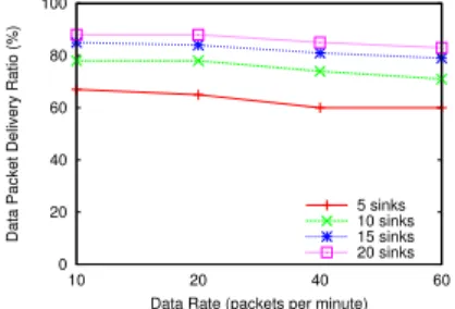
E. Impact of data overload
In this scenario, we evaluate the delivery packet ratio by increasing data generation rates in network of100 nodes using 1, 5, 10, 15, and 20 sinks. Data packet delivery rate grows down very quickly with the increased throughput when too few sinks are deployed. Indeed, network overload increases collisions and mac buffer overflows in linear WSNs and generates packet loss. The throughput of a node i depends on the node data rate, and of the data rates of all the nodes using them as a relay. The data rate at the output of any intermediate network node to the sink can increase very quickly.
0 20 40 60 80 100 10 20 40 60
Data Packet Delivery Ratio (%)
Data Rate (packets per minute) 5 sinks 10 sinks 15 sinks 20 sinks
Figure 9: Data Delivery Packet Ratio in network of 100 nodes with various rates
Figure 9 shows that the data packet delivery rate degrades when increasing throughput but this effect can be mitigated by augmenting the number of sinks. The reduction of the average number of hops to the sink can not fully avoid packet loss caused by collisions. That kind of problem can be solved by using a well suited MAC as described in [15].
Evaluations (Figure 7 and 9) show that we obtain a good average data packet delivery ratio (> 85) in network where a ratio nbSink/nbN ode > 0.10. In this configuration, networks are close to multiple small cluster networks. When nbSink/nbN ode < 0.10, evaluations show an average data packet delivery ratio close to 65%.
VI. CONCLUSION
In this paper, we propose a robust discovery, addressing and routing protocol for dynamic linear WSN. This mechanism provides add new spare nodes or branche of nodes and hierachical routing to multiple-sink. Sink nodes (or whole branches) can be added either at the initialization of the linear network or later with Dynamic DiscoProto to solve network overload or network latency problem. The routing mechanism using a hop count metric provides a load balancing of traffic to
the sinks, reduces data packet latency and increases data packet delivery ratio. The evaluation of node addition in the Castalia simulator shows that it can be adapted for large Linear WSNs but can cause latency in dense WSNs with many overlapping branches. The implemented routing algorithm supports new addresses bloc reallocation and ensures efficient data routing for entire network.
However, as routing cannot solve all the problems specific to a linear WSN, we plan to focus on two different levels: To reduce congestion, we are working on an aggregation approach. To minimize the probability of collisions and take advantage of the specific structure of linear WSNs, we plan to adapt a fully linear MAC protocol using a token approach to partially linear WSNs.
REFERENCES
[1] R. Sokullu and E. Demir, “A comparative study of MAC protocols for
linear WSNs,” Procedia Computer Science, vol. 52, pp. 492 – 499, 2015.
[2] I. Jawhar, N. Mohamed, and D. P. Agrawal, “Linear wireless sensor
networks: Classification and applications,” J. Netw. Comput. Appl., pp. 1671–1682, September 2011.
[3] I. Jawhar, N. Mohamed, and K. Shuaib, “A framework for pipeline
infrastructure monitoring using wireless sensor networks,” in Wireless
Telecommunications Symposium, 2007. WTS 2007. IEEE, 2007, p.
1–7.
[4] M. D. Sarr, F. Delobel, M. Misson, and I. Niang, “Automatic discovery
of topologies and addressing for linear wireless sensors networks,” in
Wireless Days (WD), 2012 IFIP. IEEE, 2012, pp. 1–7.
[5] M. Zimmerling, W. Dargie, and J. M. Reason, “Localized power-aware
routing in linear wireless sensor networks,” in Proceedings of the 2nd ACM international conference on Context-awareness for self-managing systems, ser. CASEMANS ’08. New York, NY, USA: ACM, 2008, p. 24–33.
[6] S. Kim, S. Pakzad, D. Culler, J. Demmel, G. Fenves, S. Glaser, and
M. Turon, “Health monitoring of civil infrastructures using wireless sensor networks,” in Proceedings of the 6th international conference
on Information processing in sensor networks. ACM Press, 2007, pp.
254–263.
[7] S. Park, E. J. Lee, J. H. Ryu, S.-S. Joo, and H. S. Kim, “Distributed
borrowing addressing scheme for zigbee/IEEE 802.15.4 wireless sensor networks,” ETRI journal, vol. 31, no. 5, p. 525–533, 2009.
[8] M.-S. Pan, H.-W. Fang, Y.-C. Liu, and Y.-C. Tseng, “Address
assign-ment and routing schemes for zigbee-based long-thin wireless sensor networks,” in IEEE Vehicular Technology Conference ’08, Spring 2008, 2008, pp. 173–177.
[9] L. Mottola and G. P. Picco, “Muster: Adaptive energy-aware multisink
routing in wireless sensor networks,” IEEE Transactions on Mobile Computing, vol. 10, no. 12, pp. 1694–1709, Dec. 2011.
[10] M. O. Farooq, C. J. Sreenan, K. N. Brown, and T. Kunz, “Rpl-based
routing protocols for multi-sink wireless sensor networks.” IEEE
Computer Society, 2015, pp. 452–459.
[11] M. Migabo, K. Djouani, A. Kurien, and T. Olwal, “Gradient-based
routing for energy consumption balance in multiple sinks-based wireless sensor networks,” Procedia Computer Science, vol. 63, pp. 488 – 493, 2015.
[12] S. Moonjoo, K. Dongkyun, Y. Hongseok, and H. K. Kyu, “Global:
A gradient-based routing protocol for load-balancing in large-scale wireless sensor networks with multiple sinks,” 2010 IEEE Symposium on Computers and Communications (ISCC), pp. 556–562, 2010.
[13] A. Boulis, “Castalia : A simulator for wireless sensor networks.”
https://castalia.forge.nicta.com.au.
[14] “OMNeT++ : A discrete event simulator.” https://omnetpp.org/.
[15] E. H. M. Ndoye, F. Jacquet, M. Misson, and I. Niang, “Using a token
approach for the MAC layer of linear sensor networks: Impact of the node position on the packet delivery,” in 2014 IFIP Wireless Days, WD 2014, Rio de Janeiro, Brazil, November 12-14, 2014, 2014, pp. 1–4.