Building An Interactive Occupant Packaging Model With
Human Figure
by
Megan Cathleen Jasek
Submitted to the Department of Electrical Engineering and Computer Science
in partial fulfillment of the requirements for the degrees of
Bachelor of Science in Computer Science and Engineering
and
Master of Engineering in Electrical Engineering and Computer Science
at the
MASSACHUSETTS INSTITUTE OF TECHNOLOGY
June 1995
@
Megan Cathleen Jasek, MCMXCV. All rights reserved.
The author hereby grants to MIT permission to reproduce and distribute publicly
paper and electronic copies of this thesis document in whole or in part, and to grant
others the right to do so.
A uthor
... v..
; ' ' "
.-
... ,...
Department of Elect cal Enginekrng and Computer Science
/
May 12, 1995
,~r)
Certified by ... . ... . ... ...
Sb
David Zeltzer
Principal Research Stientist, Researc Laboratory of Electronics
Thesis Supervisor
Accepted by ...
.
'...
.
. .
Chairman, Department Com ittee
iASSACHUSETTS INSTU'ITT OF TCHN~0LOGY
AUG 101995
. . .. . .. . . . . . . .. . . . . .F. R. Morgenthaler
on Graduate Theses
LIBRARIES rk E0 r I6 ki I
Building An Interactive Occupant Packaging Model With Human Figure
by
Megan Cathleen Jasek
Submitted to the Department of Electrical Engineering and Computer Science on May 12, 1995, in partial fulfillment of the
requirements for the degrees of
Bachelor of Science in Computer Science and Engineering and
Master of Engineering in Electrical Engineering and Computer Science
Abstract
The first Occupant Packaging Model (OPM) system was created. The OPM system is a human factors analysis tool which allows industrial designers visual access to template cockpits and AliasTM concepts in a three-dimensional interactive environment. For a com-plete evaluation, it incorporates interaction with a computer human model and visually displays simple human factors data. These four modules of OPM were implemented with straightforward algorithms and provide a foundation for this type of tool. Expanding these algorithms will provide industrial designers with a product that helps them improve con-cept design through improved usability by examining human movement in the cockpit and improved aesthetics by visualizing all cockpit objects together.
Thesis Supervisor: David Zeltzer
Acknowledgments
All of my co-workers at Delco were extremely pleasant and fun to work with. I would like to acknowledge the leaders of the User Interface Development group, Kathy McCombs and Mark Adamski, as well as the rest of the industrial designers for teaching me what design means. I would like to thank Delco for its financial support during the first six months of this project.
I would like to thank David Zeltzer for accepting the responsibility to supervise my thesis and being the coolest supervisor I know. (Except for that one day when he threatened that I would not graduate this term.)
The VETT lab has been a crutch to my experience. I especially appreciated the help from Rakesh Gupta and Nick Pioch and the feedback and ideas from the rest of the lab members.
I would also like to thank the fate of the world for giving me an outstanding life full of opportunities and making me the luckiest woman in the world.
Finally, I would like to thank whoever is in change of the job market for making it incredibly easy for me to find a job in my field this year.
Contents
1 Introduction 13
2 Related Work 15
3 OPM Requirements 19
3.1 Characterization of Users ... 21
3.2 Graphical User Interface (GUI) ... 21
3.3 Integrated Cockpit ... 22
3.4 Human Figure Model ... 23
3.5 Human Factors Data ... 24
3.6 OPM Requirements Summary ... 24
4 Code Structure and Design 27 4.1 The 3d Language ... ... 27
4.2 Modularization of Code ... 28
4.3 Coding Conventions ... ... . 28
5 Interaction with the Alias Modeling System 31 6 Graphical User Interface 33 6.1 Design and Positioning of Windows .... .... . . . .... .... . . 33
6.1.1 Main W indows ... ... .. 34
6.1.2 Information Windows ... .. 36
6.1.3 Color Scheme ... ... ... .. 37
6.2 Command Loop ... .... .. . 37
6.4 Identifying Coordinates ... . ... . 39
6.5 U nits . . . ... . . . ... . . . . . 39
6.6 H elp . . . .... . . . .. . . .. . 40
7 The Integrated Cockpit 41 7.1 Cockpit Templates ... ... .. 41
7.1.1 Directory Structure of Components . ... 42
7.1.2 File Capabilities ... .44
7.1.3 Dimension Capabilities . ... . . . . 46
7.2 Design Concepts ... 51
7.2.1 Loading and Removing Concepts . ... . 51
7.2.2 Internal Concept Structure ... 53
7.2.3 Translating and Rotating Concepts . ... 53
7.2.4 Simple Alias Concepts ... 53
8 The Human Figure 55 8.1 Loading, Removing, and Translating the Human . . . . 55
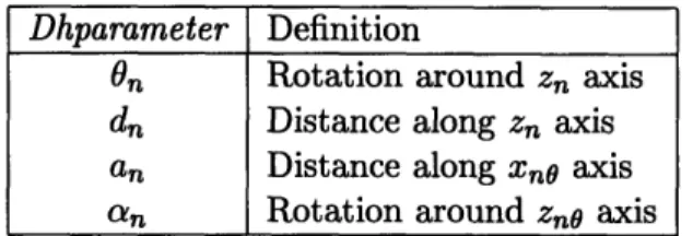
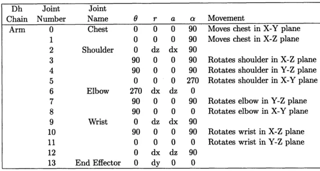
8.2 Denavit-Hartenberg Specification . ... . . . . . 56
8.3 Animation ... . ... ... ... ... 59
8.4 Collision Detection ... . ... . ... 62
8.5 Forward Kinematics ... 62
8.6 Inverse Kinematics ... ... . . 63
8.6.1 Calculation of the shoulder _elbowvector . ... 64
8.6.2 Calculation of the arm angles . ... . . . 66
8.7 Anthropometry . . . . . ... . .... . . . ... . . 69
8.8 Alias Figures ... 70
9 Human Factors Information 71 9.1 The Sight Cone ... . 71
9.2 The Eyellipse ... ... .... .. ... ... .. 72
10 Evaluation 77
11.1 Modular Enhancements ... 79
11.2 Summary of Enhancements ... 82
12 Conclusions 83
List of Figures
4-1 Modular dependency diagram for OPM code . ... 29
6-1 Main windows of the graphical user interface . ... 35
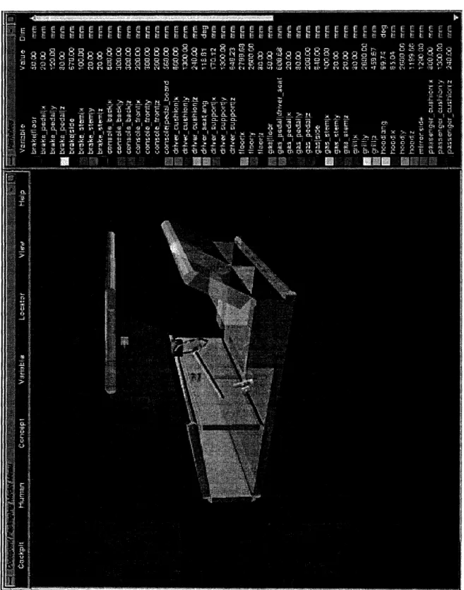
7-1 Cockpit with radio concept and Variables window . ... 47
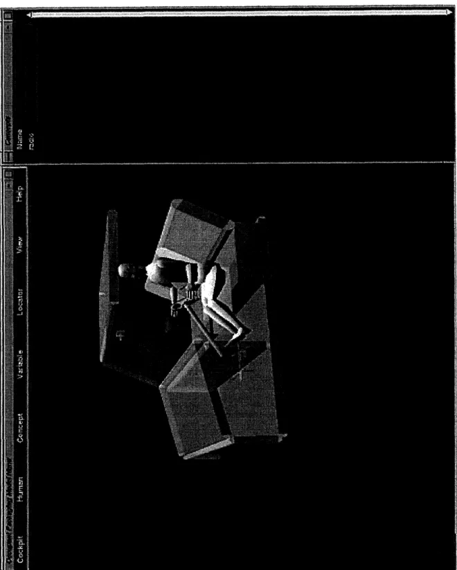
8-1 Large, male human model loaded into a cockpit . ... 57
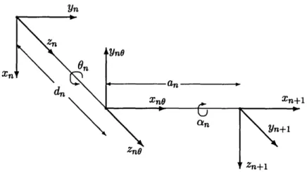
8-2 Transformation between joint n and n + 1 on a dhchain . ... 58
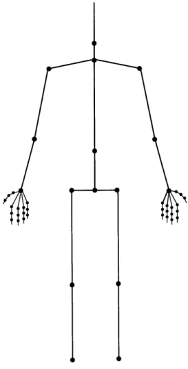
8-3 Locations of the joints for the human figure . ... 60
8-4 Arm vectors for inverse kinematic calculations . ... 65
9-1 Sight cone added to an average, female human model in the cockpit environment 73 9-2 Close up view of the eyellipse added to an average, female human model in the cockpit environment ... 75
List of Tables
7.1 Exact directory paths for the body components of a cockpit ... 43
7.2 Exact directory paths for the parts components of a cockpit ... 43
8.1 Definitions for Denavit-Hartenberg parameters . ... 56
8.2 Denavit-Hartenberg parameters for the arms . ... 61
Chapter 1
Introduction
There is a new idea on the horizon of interior automotive electronic concept design called The
Integrated Cockpit. This notion strives to bring the design of all of the interior electronic
components of a car together with the cockpit itself. Currently, automotive industrial designers are trying to synthesize this complicated world by studying the pieces separately. It would be beneficial if they had a tool that enabled them to visualize their new designs
both individually and with the rest of the automobile interior.
Delco Electronics recognized opportunity and strived to create a visual tool so that designers could capture all of their designs together in the cockpit and easily manipulate them. In the process, they realized that they could also visualize other information in this virtual world such as human factors and occupant packaging data. To make the picture complete a computerized human model could be added with simple movement capabilities to interact with the components of the cockpit and the new concept designs. There have been few previous systems that have tried to integrate cockpits, design concepts, a virtual human, and human factors data, let alone with a visual tool.
A tool like this will benefit the design process in multiple ways. First of all, it will help the designers create more aesthetic and functional designs by enabling them to look at all of the components in the cockpit simultaneously. Knowing how a human can interact with what they build will facilitate more usable products. Secondly, it will bring gross design errors to the forefront, so that they can be corrected before any prototypes are built. Overall, it will save money by decreasing the number of prototypes that need to be built while increasing the quality of interior component design.
This project broke new ground as it attempted to create the first OPM (Occupant Packaging Model) system. The objective of this project was to build a human factors analysis tool for the User Interface Development group at Delco Electronics in Kokomo, Indiana. In designing this tool, attention was paid to the needs specific to Delco and design issues were dictated and constrained by their desires and resources. The tool allows the user to bring up a template of the cockpit of an automobile in a three-dimensional
interactive environment and load new design concepts from the Alias1 modeling system.
Human interaction with the cockpit and the new concepts can be effected by bringing a human figure into the environment and performing simple manipulations. Furthermore, simple human factors data can be visualized using the main menu.
The requirements, implementation, and evaluation of the OPM system are described in the rest of this thesis. Chapter 2 outlines related work in the fields of human animation and occupant packaging. The overall requirements and specifications are detailed in chapter 3. Chapter 4 describes some general coding guidelines. The Alias modeling system and how it relates to this project is described in chapter 5. The next chapter examines the function and design of the graphical user interface. The features for the cockpit templates and the design concepts are described in chapter 7. The implementation of the human figure including the Denavit-Hartenberg specification, collision detection, forward and inverse kinematics, and anthropometry are explained in chapter 8. Chapter 9 summarizes the human factors information that can be visualized. Finally, the last three chapters include an evaluation of the project, considerations for future work, and concluding remarks.
The following are conventions that will be followed throughout this thesis. The terms
user and designer will be used interchangeably to denote the users of the OPM system.
The term design concept also referred to as concept is defined as any interior automotive electronic component design. The symbol 3d refers to the computer language in which the OPM system was written, whereas, 3D refers to the three dimensions in the world. The terms cockpit, template, and project will be used interchangeably to refer to a cockpit model used in the OPM system.
Chapter 2
Related Work
Delco's goal was to find a system that explored the use of graphical technology by integrating cockpits and humans, but required a minimal investment of their resources. Through an informal review of the present systems that do this kind of work, they found that the currently available systems were incomplete, too complex, too expensive, or a combination of all three. Consequently, they set out to build a system of their own.
Norman Badler and his colleagues at the University of Pennsylvania have done extensive work in human figure animation. Badler has created the Jack system [BPW93] for work with human factor analysis in its many different applications. The goal of the system was to model a human figure with reasonable biomechanical structure and form and then use this system in human factors applications ranging from population studies to comfort evaluation of new products. The Jack system encompasses a wide range of aspects concerning the human figure. On the most basic level it investigates how to model the human body. The Jack model is complex because it includes a flexible torso that simulates a multi-vertebra being and incorporates strength when moving and guiding body parts. In addition to low-level modeling, Jack also deals with the spatial interaction of the human with its environment including issues concerning the reachable space around the human. On a higher level, it considers the coordinated tasks that the human can perform using its base biomechanical movements including attempts to integrate behavioral control with human action.
Jack provides a great deal of information about the shape and movement of a human
on the needs of Delco the comprehensive capabilities of the Jack system are unnecessary. Delco wanted to experiment with this type of technology to see if it were useful by creating a simple prototype. If the benefits proved worthwhile, then more time and money would be invested in this type of work. The project need only handle the form of the human and its simplest biomechanical movements for Delco's purposes. An analysis of high- level tasks and cognition would be extravagant.
Swetlana Gaffron did work that was similar to Badler's work in computer human ani-mation with her Skillbuilder tool [Gaf94]. Her program was designed to provide a model of a human figure that functions in a virtual world. It is an autonomous model that can independently carry out movements in its environment. The goal of her work was to create a library of motor programs that execute motor skills. When combined, these motor skills created high-level actions, so the user could manipulate the human figure without having to specify a large set of low-level data. Gaffron's project focused on enabling the computer figure to reach, grasp, and manipulate a simple object.
Gaffron's work spends too much time coordinating high-level movements and is incom-plete. Her figure can carry out tasks that are more complicated than the tasks needed for this project and that only use one limb. She goes into much more depth when specifying the actions that the figure will perform and has only created actions for a small part of the human body.
In the mechanical engineering field, there is a group of software tools dealing with the analysis of multibody systems that are used in modern mechanical computer-aided engineer-ing (MCAE). Engineers can perform kinematic, static, and dynamic analyses of mechanical systems. The oldest and most widely used of these programs is called ADAMS for Au-tomated Dynamic Analysis of Mechanical Systems [Rya90O]. The program is designed to characterize the overall motions of complex rigid and flexible mechanical systems. By ac-curately predicting the interactions of subparts of new system designs, important analyses can be made that highlight system design errors before expensive prototypes are built. The ADAMS system uses the fast computational abilities of a computer to develop a mathe-matical model for the system, formulate equations governing the behavior of this model, and find a mathematical solution for the system. The inputs to the program consist of descriptions and constraints of the subparts of the system being studied. Outputs include positions, velocities, and forces of the components in the form of tables, figures, and graphs.
ADAMS also has an Android module that enables it to model a human figure to be used for interaction with a multibody system.
Delco could have used ADAMS to set up a model of the cockpit of a car, convert new automotive interior designs to be included with the cockpit, and create a human figure with the Android module. ADAMS would have carried out the necessary human actions and then given a detailed analysis of the motion of the system. Unfortunately, there is very little motion that needs to be analyzed. A typical radio design does not have much movement aside from turning a knob. The ADAMS system performs a great deal of mathematical computation on the mechanical system that is unneeded for this project. Delco is more interested in the display of human interaction with new designs and some of the specific human factors data that is associated with it.
There are a number of other human movement systems that were not appropriate be-cause they did not exhibit the desired behavior. For example, Thalmann and Magnenat-Thalmann created the Human Factory which can perform automated walking and grasping behaviors, but focuses on key frame-like animation that is better suited for making movies than for real-time human interaction [MTT90, MTT91]. Finally, the PINOCCHIO system described by Maiocchi and Pernici is capable of modeling realistic human movement. Since this system relies mostly on pre-recorded human movements to control virtual characters, it has a limited capability for describing interactions with other objects in a scene [MP90]. Delco Electronics and General Motors are continuously doing work in occupant packag-ing'. Ron Roe investigated the development and application of SAE (Society of Automotive Engineers) tools used in occupant packaging [Roe91]. His work describes how these tools are used to define spatial constraints for occupants in motor vehicles. In order for the vehicle to be designed correctly, it is necessary to establish the available interior space and arrange the interior components using safety requirements for each of the occupants of the vehicle based on vehicle type. Roe also explains how these spatial requirements are calculated and how the human beings for which they are designed are measured. Some of the available occupant packaging tools that are used for spatial measurement include
the H-point machine, eyellipses2
, head position contours, and hand control reach envelopes. Roe emphasizes the need to continue developing occupant packaging data and to compile
1The study of comfortably fitting (packaging) human beings (occupants) into automobiles.
2
the current set of data that already exists.
This project uses some of the tools and definitions described by Roe and attempts to visualize this data.
Chapter 3
OPM Requirements
The idea for this project was generated by the User Interface Development group at Delco Electronics. The program was a supplementary project in the group intended to be an experiment to survey the capabilities of graphical technology. As a cooperative student at Delco, I was given the challenge of exploring the possibilities for this technology and thus had a large amount of freedom to design the system according to my inclinations.
The OPM system was designed to visually synthesize the integrated cockpit, human figure interaction with that cockpit, and human factors data. The visual aspect of the system was implemented through a graphical user interface. Cockpit and concept features are available to incorporate the integrated cockpit. Human figure interaction is provided through a computer model of a human figure and features that allow movement of this figure. Human factors features allow for the display of human factors data.
The following describes a typical session an industrial designer might have involving the OPM system. The process starts with the Alias modeling software. Using Alias, the user creates a new automotive design concept that combines the radio with the cellular phone. The concept is unique because it is twice the height of a standard double DIN' radio and it integrates two features into one unit. The concept is saved from Alias to a polygon format and then converted to ascii format to be used by the OPM system. To begin, a template cockpit and the new concept are loaded into the 3D environment of OPM. The radio unit is rotated and translated to a user-chosen position. OPI (the Occupant Packaging Individual) is loaded into the scene as a large, male human model. By maneuvering the positions of
OPI's arms, the designer can understand if OPI can reach the new concept with his hand. The reachability of the concept by a small, female can also be checked by loading a different human model. Should the designer wish to add another concept to the scene or move the current one, he or she can optimize placement of this concept by knowing which regions OPI can see best. These regions are identified by defining a sight cone for the system that enables the user to visualize what OPI can see in a specific viewing radius. During this process, the user can use the mouse to change the view point of the scene to look at any aspect of the cockpit or concept from different angles. The designer also begins to understand what the new concept will look like among the components of the cockpit and with other concepts.
This system is composed of four different parts.
1. The graphical user interface (GUI)
2. The manipulation and storage of cockpits and concepts
3. The interaction with a computerized human figure model
4. The visualization of human factors data
The focus of the project is for the user to experience the consequences of the ensemble of these four subprojects. Even though complex descriptions exist for these parts individually, only simple ones were implemented so that users could understand what happens when they are brought together. In the future more complicated algorithms could be implemented. In summary, the important idea is having all of these elements in the same place at the same time, not how complex the elements are individually. In addition to focusing on simple algorithms, the implementation also meets the requirements of the designers at Delco, but was designed to be flexible should those requirements change. The requirements focus around the ease of use by end users, modeling the four parts described above, and handling output from the Alias modeling system.
The subsequent sections of this chapter describe the requirements of the OPM system specified by the industrial designers at Delco Electronics for each of the four modules of the program. Following the requirements is a brief overview of the implementation of each module.
3.1
Characterization of Users
The users of the OPM system will be the industrial designers at Delco. According to Cotterman and Kumar in User Cube: A Taxonomy of End Users [CK89] they are classified as (0, 0, 0.3) on the User Cube, which means that they will be end-users of the system and have some control over the resources used in developing OPM, but will not be heavily involved with the computer development or operation of the system. Consequences of this on system design are that if something were to go wrong with the operation, development, or maintenance of OPM, there would always be a way in which the user could get help or start
over. In addition, most of the users are not frequent users of the UNIX2 operating system.
Since OPM was built for a UNIX system, any references to directories, other UNIX-specific items, or computer science jargon will have to be thoroughly explained in help sections or avoided completely. On the other hand, since they are industrial designers whose work commonly consists of representing ideas visually, it is expected that it will be easy for them to understand the graphical tools of the system. Finally, the users are human beings which means that it will be common for them to make mistakes when carrying out system tasks. Therefore, it is important to have the ability to reverse actions or cancel them completely and give warnings indicating an input error.
3.2
Graphical User Interface (GUI)
The requirements for the user interface were as follows. On the most basic level it needed to be easy for the designated users to use and have easy access to the information of the OPM system. The users wanted a large three-dimensional space for viewing graphical system objects. They also expressed a need to have viewing capabilities to enable the user to zoom in on a particular component in the cockpit or rotate the view of the cockpit. Viewing needs also included the ability to click to a head-on view of one of the three major planes. Since the system functions in three dimensions, there also needed to be some form of quantitative measurement, so that the user has a sense of where particular coordinates are in the scene. The user interface has been designed so that it is as friendly as possible, so that the industrial designers can use it to its potential. Its three major parts are the main menu,
2
the auxiliary information windows, and the Display window. The main menu is a long, thin window that runs horizontally across the top of the screen and displays buttons for the major functions of the system. The auxiliary information windows take up the the right one-fifth of the screen and can display three different kinds of information. Dimensioning information for the cockpit is displayed in the Variables window. Location information is displayed in the Locators window. This window provides output from the locators feature which enables the user to graphically show a point in the coordinate space of the Display window, move this point around, and create more points. Essentially, the window shows a list of coordinates of user-specified points; their locations are shown graphically in the Display window. The third information window displays information about the design concepts loaded into OPM. The rest of the screen consists of the Display window which provides a large space for viewing cockpits and concepts, so that the user can use an extensive portion of the screen to look at objects. Other windows that pop up as a result of one of the system features are placed in convenient positions so as to allow the user to see the necessary information to use the feature. In general any new windows are brought up in the lower left corner of the screen and help windows are brought up directly above the feature windows. Viewing capabilities are handled by a button on the menu that allows a user to go into Mouse mode which gives them the capability to use the mouse to change the view of the scene or to click the view to look head-on at the X-Z, X-Y, or Y-Z planes.
3.3
Integrated Cockpit
The designers needed to view the whole cockpit including design concepts, so that they can move towards a more integrated approach to concept design. This would help them move away from the idea of designing the parts outside of the cockpit without taking the rest of the interior into account. An essential part of this idea was to view the cockpit visually in three dimensions. Certain features were required to be included in the cockpit. In addition to the standard seats and body parts, the designers requested the rear-view mirror, the acceleration pedals, and a console. It would be helpful if the user could see the dimensions of the car and were able to modify them to correspond to a particular automobile model. The car used for this project is the 1993 Chevrolet Cavalier. Most likely templates will be created for each name plate (by the designers). The current name plates include Chevrolet,
Cadillac, Buick, Geo, Oldsmobile, Saturn, and Pontiac. In addition to modification in the OPM system, the user requested modification of any of the cockpit components in Alias, so that they could be custom designed in the 3d environment. Generally, the user needed the ability to load or remove a default template and save modified templates under an original name. On the concepts side, the user needed to be able to load and remove concepts created in Alias into one or more cockpits. After loading, the user needed to translate and rotate the design concepts. For the most part the designers will be looking at radio panel and air control cluster designs.
The capabilities for handling cockpit templates were designed to be flexible. The user can load the template cockpit into the three-dimensional Display window and then modify and save this cockpit in a different directory. To facilitate modification, the common dimensions of the cockpit are displayed in the Variables window. More than one template can be loaded, so that the user can evaluate the same concept in many different cockpits. In addition to being able to modify the cockpits in the 3d environment the user can also modify the template parts in Alias and then load the new parts into 3d. (The user has to be aware that the name of the object that is being modified cannot be changed.) This allows the user to create elaborate templates if necessary, but since the common case will be to use a simple template that is the default.
Concepts can be loaded and removed in the same manner as cockpits. More than one concept can be loaded into a cockpit and the user can load a concept into multiple cockpits in one step. The concepts cannot be changed in the 3d environment. In order to change a concept it must be modified in Alias and then converted back to the OPM format. The OPM is designed for use with simple Alias designs that contain on the order of fifty polygons. This specification should not be problematic because the level of detail that needs to be displayed is low. One cannot see a great level of detail in 3d, so many of the polygons would be wasted anyway.
3.4
Human Figure Model
The requirements from the designers for interaction with a human figure were relatively simple. The user needed to load a human figure into the driver's seat of the cockpit in the sitting position. It would be beneficial if the figure could be minimally translated backward
or forward in the seat. The figure should also be able to perform simple forward kinematic tasks and make other simple body movements. It was essential that there be multiple sizes of both male and female figures.
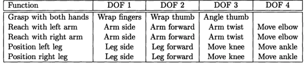
A male or female human figure of large, average, or small size can be loaded into the environment. The human being has both forward and inverse kinematic capabilities. The forward kinematic capabilities include being able to move each joint of the figure in any of the planes that it has valid movement. Some of the other forward kinematic procedures include grasping the steering wheel and reaching for a certain object. The inverse kinematic procedures allow the user to tell the human figure to move its arm to a certain point in space or to move its arm as close to an object in the template as it can. Movement of the human figure around the scene is also available in a limited manner.
3.5
Human Factors Data
The designers suggested that it would be useful to be able to identify the sight regions that the driver could see best and looked at most frequently. It would also be useful to have the standard eyellipse calculated and displayed for a particular human being in a particular automobile.
There is no real limit to the amount of human factors data that can be represented in this project. Two tools were chosen for illustration purposes. A sight cone was implemented that shows the cone of vision that is most comfortable for the average human being. The dimensions of this cone can be modified to create a customized object. The other informa-tion that is represented is the eyellipse. A dialog box allows the user to characterize the eyellipse according to General Motors' standards.
3.6
OPM Requirements Summary
The user should be able to:
* Easily use OPM even if he or she is not a UNIX user * Have a large viewing space
* Locate coordinates in three dimensions * View the cockpit and concepts together
* Include specific cockpit components such as seats and mirrors * Modify and save dimensions of cockpits
* Customize cockpit components in Alias * Load design concepts created in Alias * Translate/rotate design concepts * Load a human driver of different sizes
* Modify the positions of the body parts of the human model * Identify sight regions
Chapter 4
Code Structure and Design
The OPM project runs on a Silicon Graphics machine with the UNIX operating system. Because of its speed requirements, it runs best on an Indigo2 Extreme or an Onyx. These media were chosen because of the resources available at Delco Electronics. In order to use OPM, the user must have access to the source code of the OPM system which is stored in the directory /usr/people/megan/cockpit. To boot the program, the user types OPM.
4.1
The 3d Language
About 95% of the OPM code was written using the 3d Virtual Environment/Dynamic Sim-ulation Language [ZC92]. This language, which was developed at MIT, allows application developers to easily design and implement virtual environment interfaces, develop inter-active simulations, and specify behaviors for virtual worlds. 3d uses tcl (tool command language) and tk which were developed at Berkeley [Ous94] for an interpreted, rapid pro-totyping front-end. Tcl is a scripting language whose syntax is similar to that of a UNIX shell. Tk is an extension to tcl which allows for construction of MotifTM user interfaces. The tcl foundation enables developers to use the 3d language to quickly create prototypes of new virtual world applications. Because of its interpreter, a designer can easily debug procedures in tcl and then implement them to run faster in C. 3d extends tcl by adding commands for objects, viewing, lighting, rendering, numerical math, matrices, and Denavit-Hartenberg joint notation. The data types supported in 3d include strings, objects, and Denavit-Hartenberg chains.
4.2
Modularization of Code
The OPM system consists of approximately 16,000 lines of code broken up into twenty-eight
tcl files and four C files. Each file contains a group of procedures that relate to a specific
topic. For example, the cockpit .tcl file contains all of the code that defines the features
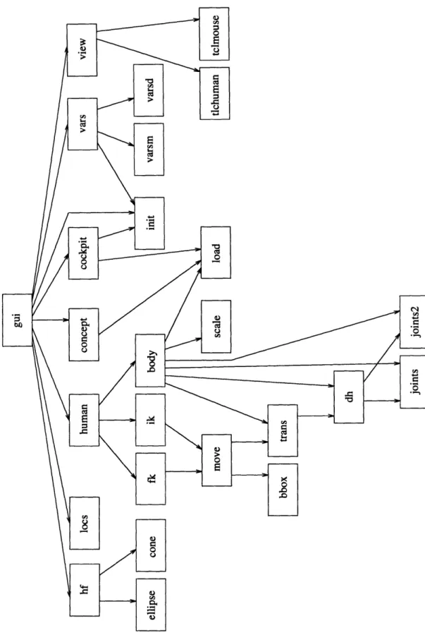
that manipulate cockpits. The twenty-six application specific files are shown in the modular dependency diagram (MDD) in Figure 4-1.
Each box in the figure has the name of one of the source code files of the project. An arrow going from box A to box B means that the code in the file of box A depends on the code of box B. The main file is gui.tcl. Notice how it depends on the code for all of the main features of the project. It brings up the main windows of the application and initializes all of the necessary variables. The code for most of the features can be handled in two or three files. However, about one third of the code is involved in creating and manipulating the human figure. As a result the human.tcl file depends on eleven other files. The other six tcl files that are not shown in the MDD contain helper code. These are general procedures that do things like identify if a number is an integer or display an information window.
4.3
Coding Conventions
All procedures written for the OPM system begin with the requires, modifies, and effects clauses [LG86] which exist as comments in the code. This is a software engineering technique used to specify functions. By keeping code documented in this way it is easy to see how data is manipulated throughout the application. The requires clause lists any conditions which must be true before the procedure is entered. In general, it is best to eliminate these clauses when possible, so that code can be re-used at any time without first satisfying certain conditions. The modifies clause describes any data structures that are changed during the execution of a procedure. Finally, the effects clause indicates how the data structures are changed and what value the procedure returns. Comments are also included throughout the code.
Figure 4-1: Modular dependency diagram for OPM code
Chapter 5
Interaction with the Alias
Modeling System
The OPM system was designed to be used in conjunction with the Alias modeling software (AutoStudio version 5.1). Delco Electronics has just purchased two copies of the Alias software to be run on their Indigo2 Extreme and Crimson Elan Silicon Graphics machines. The company is trying to convert to the Alias system for some of its concept design work. The Alias product is a widely used modeling software package. As their slogan suggests, it allows the user to convert creative ideas into perfect surfaces. Anything from the simplest black box to the most detailed automobile can be created with Alias through a menu of primitive objects and surface building tools. The cockpit template, the human figure, and all of the design concepts were created with Alias.
Objects created in Alias are converted into 3d format. First, an obj directory is created with the UNIX mkdir command in the project directory of the project. Second, the objects of the project are converted into polygons in the Alias environment with the Alias create
polygons feature. These polygons are saved to a file in the OBJ format (Wavefront format)
in the newly created obj directory. The files can be converted to .asc files which the
3d language accepts using the objto3d command written by Rakesh Gupta. (Note: as
long as an obj directory exists containing the .obj files, they will be converted to .asc files automatically when the project is loaded into OPM, so the user does not have to be
concerned with the conversion.) Finally, the .asc files can then be loaded into the 3d
are created in Alias for use with the OPM system will consist of a moderate number of polygons, so that the 3d environment will not be slowed down.
Currently the cockpit template is a set of simple cubes and cylinders that are saved in the main OPM directory and that cannot be overwritten by any of the users of the program, so that there will always be an original cockpit template that can be loaded. Since the focus of this project is on the human interaction and the design concepts it is not anticipated that the designers will desire a detailed, complicated cockpit template. However, should a designer need to enhance one of the objects of the template, there is a way that this can be done. The user can copy the entire directory of cockpit objects to a newly created directory. Then any of the cockpit objects can be loaded back into Alias, modified, converted, and saved in this new directory. The directory can then be loaded into the OPM program and any modified objects will be available.
Chapter 6
Graphical User Interface
The graphical user interface (GUI) encompasses the windows of the application, how those windows are positioned and colored, and how the user can use the mouse and the keyboard to communicate with the OPM system. The main requirements for this section are that the user be able to easily access the features of the system, easily view the necessary objects at the appropriate times, quickly manipulate the view point to view the scene from different angles, and effectively locate coordinates in three dimensions.
6.1
Design and Positioning of Windows
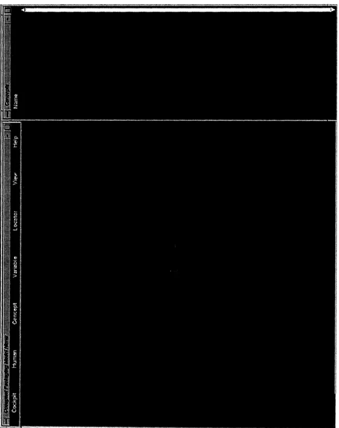
The windows of the application were arranged so that the Display window (the window that shows the 3D viewing environment) occupies as much space as possible at all times. This enables the user to see the most information in the scene. The five main windows of the application are the Display window, the main menu, and the three auxiliary windows-Variables, Concepts, and Locators. Figure 6-1 shows a picture of the main windows. These windows never change size or position when the system is running because they are the base windows of the program. The other windows of the application are called information windows and are categorized as one of three types-feature windows, warning windows, and
fyil windows. The positioning and size of these windows depends on the type of window and
the context in which the window is being used. These windows may also contain interactive items in them so that the user can communicate with the program. Buttons that the
user presses with the mouse and entry boxes in which the user types data are examples of interactive items.
6.1.1 Main Windows
The main menu is a narrow window about two centimeters high that runs from the upper left corner about three quarters of the way across the screen (see Figure 6-1). It provides access to the features of the project. The features are broken down into seven categories and are labeled starting from the left-Cockpit, Human, Concept, Variable, Locator, View, and Help. Each of these features will be explained in detail in remaining sections. By clicking the mouse over one of the these words the user pops up a menu displaying the features of that category. The user can activate a feature by moving the mouse over its name. Not all features can be activated at all times. If a feature needs certain information that is not currently available, then that feature is disabled in the main menu, so that the user cannot use it. When the appropriate information becomes available, the feature is enabled. This prevents users from activating features at incorrect times.
The three auxiliary windows are positioned lengthwise on the right of the screen as shown in Figure 6-1. Their position and shape were chosen so that they were on the side and out of the way, yet had enough length to display a long list of elements when the need arose. They take up about one-quarter of the viewing space. All of these windows give information about the objects that are displayed in the Display window. The windows are needed because it would be difficult to display text in the Display window especially since the view of the window can be alternated causing the text to become unreadable. Each element in each of these windows is associated with a color. The same color is also mapped to the element in the Display window, so that it is easy to identify the element in the Display window. The three windows are stacked on top of one another to conserve space. When a feature does something that is related to the information of a particular auxiliary window, that window is raised to the forefront, so that the user can see it. Using the mouse the user can highlight the elements in the windows. The highlighted elements are called the selection which is sometimes used to send certain elements as input to other functions. Auxiliary windows also contain scroll bars so that a large number of elements can be stored in the window.
Num-g-q.
windows will be given in later sections. The Variables window displays information about the dimension variables of the cockpit such as their name, value, unit of measure, and the color associated with them. The Concepts window displays the names of the concepts that are loaded in the environment and the colors that are associated with them. The Locators window displays the X, Y, and Z coordinates for the locators that are currently in use.
The Display window takes up the rest of the screen (almost 75% of the screen area) and shows all loaded objects in the 3d environment. It is the standard window that the 3d language generates and is positioned in the lower left corner (see Figure 6-1).
6.1.2
Information Windows
The position and size of feature windows can vary. The position is determined by what information the user needs to see on the screen to use the feature. If the user does not need to see anything or needs information from one of the auxiliary windows, then the window is placed in the lower left corner of the screen over the Display window. If the user needs to see information in the Display window, then the feature window is placed in the lower right corner of the screen covering the bottom portion of the auxiliary windows. The size of these windows is determined by how much information is displayed by the feature. More complicated features usually have larger windows and some features require more than one window at more than one location. The feature windows contain button, entry, label, listbox, and scale widgets that the user can manipulate with the mouse and keyboard. In general the window has OK and Cancel buttons at the bottom of it, but there are a few exceptions to this rule. The OK button executes the feature with the given input. A feature can be canceled without modifying the system by pressing the Cancel button. The feature windows sometimes obtain input from the auxiliary windows via the selection.
The size of warning and fyi windows varies with the message that they display, but they are usually relatively small. These windows typically have a short message on the top and an OK button at the bottom. Warning windows are always located in the same position in the lower left corner of the screen and flag the user that a mistake was made. Usually this mistake comes from entering incorrect input. Sometimes it will result from a file access error. In any case, the user is warned of the error through the text message and is given instructions on how to continue. The program will not continue until the user presses the
The 'fyi' in fyi window stands for 'for your information'. These windows simply confirm actions that the OPM system has taken or lets the user know that it is processing data. They are typically used with features that take a lot of time, so that the user is not anxious that the system has crashed. When an fyi window is used for confirmation it is located in the same position as the warning windows, however, when it is used to give feedback on what the system is currently processing it is located in the middle of the screen so that it gets the users attention.
6.1.3 Color Scheme
The colors for the application were chosen so that most of the background would be a dark color (dark forest green) and the foreground, such as text, would be a light color (off-white). When choosing colors for interfaces, it is best to avoid combining colored text with a colored background. Neutral text on a colored background gives maximum legibility [JMF94]. Minimizing the number of colors used is also wise because too many colors can distract the user. Following these principles, there are just two additional colors in the general interface-the selection color is navy blue and the highlighting color is dark red.
The colors that are used in the Display window and the auxiliary window are a subset of the colors in the rgb. txt file for the machine. They were chosen so that they would show up well against the background and so there would be a reasonable difference between each color. (They are stored in the file /usr/people/megan/cockpit/src/color/rgb.txt.) To display a color in the Display window the color needs to be in the form of a list of the red, green, and blue components of the color. Each component is a number between zero and one inclusive. To display a color in an auxiliary window the color needs to be in the form #redgreenblue. The pound sign indicates that it is a color and each component is given in hex. There is a conversion procedure that converts from one format to the other.
6.2
Command Loop
Since it is not required that the user close one feature before starting another feature, the windows of many features can be on the screen at the same time. In order to handle all of these windows at the same time, a command loop was created that waits for an action from any feature window. When an action occurs, it is processed by the appropriate procedure
in the command loop. Should the user ever need to break out of this loop the Break feature of the Cockpit menu is provided.
6.3
Viewing Capabilities
The viewing capabilities are handled by the View menu. The view consists of two parts-the view point and the lookat point. The view point is the point from which you are looking and the lookat point is the point to which you are looking. The vector that goes from one to the other is called the view normal.
The View menu contains seven features. The From Human feature changes the view point to be in the center of the human figure's eyes. (There is only one view point, so stereo vision cannot be implemented.) The system goes into a mode so that the user can use the first mouse button to change the lookat point giving the effect of looking around in the cockpit. The initial lookat point is set so that the user is looking down the normal line of
sight of the human model which is 100 down from a line extending from the eyes parallel
to the ground. The user can use the Reset button to get back to this vantage point and the Quit button to exit the mode. For convenience this mode is also exited when the user brings the mouse over the auxiliary windows.
The Mouse feature allows the user to use the mouse to manipulate the view. The first button is used to tumble (rotate) the view by keeping the lookat point the same, but rotating the view point. By pressing the second button the user can zoom the view in and out. The third mouse button is used to track (translate) the view by moving the lookat point and keeping the view point static. The Reset button brings the view back to its original vantage point. This feature was implemented so that if the user manipulated the view in such a way that he or she could not find the desired view, then the view could be reset and redone.
Mouse mode is exited by pressing the Quit button or by moving the mouse over the auxiliary
windows.
The next three view features allow the user to click the view so that the view normal is perpendicular to a pair of axes. For example, if the user selects the X-Z Plane feature then the view normal would be set so that it was perpendicular to the X-Z plane. Analogous explanations exist for the X- Y Plane and Y-Z Plane features.
The Axes feature is a checkbutton which means that repeatedly selecting this option toggles the axes on or off. Each axis is displayed in the Display window. The direction that the long bar is pointing (and where the letter is displayed) is the positive direction for that axis. When the last feature of the menu, Render, is invoked the scene in the Display window is rendered. This function keeps everything looking clean in case there are ever any extra color bits left in the Display window.
6.4
Identifying Coordinates
The next of the three auxiliary windows is the Locators window. A locator is a small, colored, sphere object in the Display window. The coordinates of this sphere and its color (chosen from the rgb. txt file discussed above) are shown in the Locators window. The user can add locators with the Add feature. Every locator starts out at the origin, but the user can change its coordinates with the Modify feature. This feature allows modification by entering coordinates and then absolutely translating the locator according to those coordinates. The user can also move the locator by adjusting three sliders for the X, Y, and Z values. The sliders always start out at zero, but can move in the positive or negative direction. When a slider is moved a distance k, the appropriate coordinate of the locator is changed by k units and then the slider springs back to the zero position. This enables a finite slider to be used to move the locator an infinite distance. Locators can be easily removed with the
Remove feature by double clicking on the appropriate locators in the Locators window. The
last two features of the Locator menu are Clear Selection, which clears the selection of the Locators window, and Show Window, which raises the Locators window to the forefront of the auxiliary windows.
6.5
Units
All coordinates and measurements are currently displayed in millimeters. However, the dimension variable exists in the source code that allows everything to be converted to centimeters. Internally, all quantities are stored in centimeters because those are the units of the 3d language. It is only the display of these numbers that is put in a specified unit. This convention makes it easy to maintain consistency and correctness of object lengths.
6.6
Help
The Help menu is the last menu on the main menu. It is a cascaded menu with an entry for each feature of the OPM system. When the user activates one of these features a window pops up. This window is always the same size and is always located just below the main menu on the left-hand side. The position was carefully chosen to be clear of any feature win-dow, of the cascaded Help menu button, and of the main menu and auxiliary windows. Each help window contains an OK button that the user clicks when finished viewing it. The con-tents of the window are the concon-tents of a file in the /usr/people/megan/cockpit/src/help directory that is named after the feature. The window contains a scroll bar so that the entire file can always be viewed.
Chapter 7
The Integrated Cockpit
Moving towards an integrated approach to cockpit design means taking the whole cockpit into account when designing concepts. Understanding what the other components of the cockpit look like and how they function enables designers to create better and more func-tional concepts. The OPM system allows the designer to initialize a cockpit to particular
dimensions and then to add new design concepts and view the scene as a whole unit. The specifications for this section require that the user be able to view the cockpit and concepts in one three-dimensional environment, so that the designer gets the feeling of an
integrated cockpit. It is necessary to have certain cockpit components visible in the mock-up
of the cockpit such as seats and mirrors to make the cockpit model closer to that of a real automobile. So that concepts can be evaluated in many different styles of cars, it is required that the user be able to modify the dimensions of template cockpits and save these changes for later use. The user should also be able to customize cockpit components in Alias and then load them back into 3d with the same name. Finally, to facilitate evaluation of new design concepts, the user needs to be able to load, rotate, and translate objects created with Alias.
7.1
Cockpit Templates
The first step to analyzing a design concept is to create a cockpit with which it can be integrated. With the OPM system a variety of cockpits can be loaded and viewed in the Display window.
7.1.1
Directory Structure of Components
As mentioned earlier in chapter 5, most of the cockpits that will be used will be modeled with the Alias modeling software and then converted to a format that the 3d language can understand. However, a user can also create a cockpit via any other method such as creating
objects using the 3d language. As long as the user ends up with all of the objects in .asc
files (that the 3d language accepts), the cockpit can be loaded into the OPM system. No matter how the cockpit is created, its directory structure must be correct, so that OPM knows where cockpit objects reside and it can keep track of the dimensions of these objects. The number and names of cockpit components are fixed; the asc files that make up these components must be stored with a certain directory structure.
Any cockpit to be loaded into the OPM system must reside in an asc directory, but this directory can be nested anywhere in the UNIX directory hierarchy (e.g. /usr/people/
megan/cockpit/asc). The idea of having a special directory name, asc, where all files to
be loaded into OPM are stored stems from the fact that most projects that will be loaded will have been created in Alias. As a feature of the Alias system, each Alias project has a directory of its own in the user's user.data directory which contains many subdirectories for the project (for wire files, lighting and such). To make things simple an asc directory is
created along with the project's other subdirectories to hold the .asc files for that project.
Another benefit of having a unique directory name is that if no asc directory exists for an
Alias project, OPM knows to check for an obj directory and convert any files there to .asc
files and create an asc directory in which to put them.
As a method of organization the cockpit objects are stored in a hierarchical directory system. The two top levels of the hierarchy are the body and parts categories and subdi-rectories body and parts must exist in the asc directory. The body directory stores all of the body objects of the cockpit like the roof, floor, and grill. The exact paths for the body objects are shown in Table 7.1.
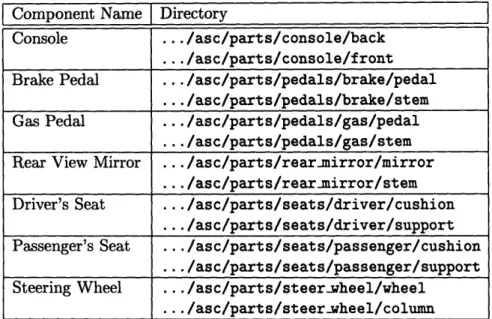
To complete the cockpit, the parts directory stores all of the other parts of the cockpit such as the console, seats, and steering wheel. Some parts are broken down further into more subdirectories. The exact paths for the parts objects are shown in Table 7.2.
The directory structure of the asc files is important because they are loaded into OPM in the exact same structure that exists in their asc directory. The purpose of this fixed
Table 7.1: Exact directory paths for the body components of a cockpit
Component Name Directory
Floor .../asc/body/floor
Grill .../asc/body/grill
Hood .../asc/body/hood
Pedal Board ... /asc/body/pedalboard
Roof ... /asc/body/roof
Windshield ... /asc/body/windshield
Table 7.2: Exact directory paths for the parts components of a cockpit
Component Name Directory
Console ... /asc/parts/console/back
.../asc/parts/console/front
Brake Pedal
...
/asc/parts/pedals/brake/pedal
.../asc/parts/pedals/brake/stem
Gas Pedal ... /asc/parts/pedals/gas/pedal
.../asc/parts/pedals/gas/stem
Rear View Mirror ... /asc/parts/rear-mirror/mirror
... /asc/parts/rearumirror/stem
Driver's Seat .../asc/parts/seats/driver/cushion
.../asc/parts/seats/driver/support
Passenger's Seat .../asc/parts/seats/passenger/cushion
.../asc/parts/seats/passenger/support
Steering Wheel ... /asc/parts/steer-wheel/wheel
directory structure is so that the OPM system knows where to look for the components of the cockpit (when it calculates dimensions of the automobile, as explained in section 7.1.3). Other benefits of the rigid structure are apparent. By having a directory for each part, the part can consist of a variable number of objects, so the user is free to modify the part without restraint. Substitutions for any of the asc files in a component's directory can be made. This can be done by creating totally new asc files or by loading the existing files back into Alias, modifying them, and converting them back to asc format. Another positive side effect of the directory structure is that in the common case the user will not be modifying the components at all, so for maximum efficiency it is best to have a system where the default is no user activity.
7.1.2 File Capabilities
The file capabilities of OPM are similar to those of other systems that have input/output through files. The OPM system provides load, save, and remove features and a feature to exit the system completely. That action is invoked through the Quit feature of the Cockpit menu.
Loading Cockpits
Loading a cockpit into the OPM system means loading an asc directory that has the proper directory structure (explained above) of cockpit components. All of the components must have asc files that represent them. The user can load a cockpit using the Load feature of the Cockpit menu in two different ways. A new set of files for a cockpit can be loaded from a given directory, or a cockpit that has already been loaded, but is currently hidden, can be redisplayed.
Loading a new set of files requires that the user specify the directory from which to load files and provide a local project name. The user inputs the complete path name of the asc directory of the cockpit project. A local project name must be created by the user, so that the OPM system will have a way to refer to the cockpit throughout its lifetime. User-specified local names should be chosen so that the corresponding project is easily identified. The template cockpit model is stored in the /usr/people/megan/user.data/cockpit/asc directory.
only display one cockpit at a time. This cockpit is internally referred to as the current cockpit and all features and functions are applied to it. After an initial cockpit is loaded and the user would like to load another cockpit, instead of removing the original cockpit the user can hide it, so that it can be displayed later. When using the Cockpit->Load command, if hidden cockpits exist they are listed out for the user. Loading one of these hidden projects requires that the user pick the cockpit to be viewed from the list. The
current cockpit is reset to this cockpit.
Since only one project can be displayed at a time, when the user wants to load multiple cockpits, he or she has to tell the OPM system what to do with the current cockpit. The user can choose to remove the cockpit completely from the system which involves deleting all of the component objects from the 3d environment. Another option is to hide the cockpit to be used later which involves unposting all of the cockpit objects, but they still exist in the 3d environment.
Once a cockpit is loaded into the 3d environment and the current cockpit is set, the OPM system makes all of the objects transparent to a moderate degree. This ensures that the user can see other objects that will be displayed in the cockpit like design concepts or cockpit dimensions. Also, distinguishing a current cockpit enables all of the other features of the main menu that interact with cockpits.
Saving and Removing Cockpits
As will be explained in section 7.1.3, the cockpit can be modified to a certain degree by changing the dimensions of the components. Once this is done, the user may desire to store this customized cockpit. This is possible by using the Save feature of the Cockpit menu. Using this feature the user can save any of the cockpits that are loaded in the 3d environment at one time. (This includes hidden cockpits.) Before executing the function the user must specify the exact directory to which to save a cockpit. A default directory is suggested to the user by OPM which is the directory to which the cockpit was last saved or if this is the first save, it is the directory from which the cockpit was loaded. However, the user is free to change this directory to any directory for which he or she has write access.
The Save Current feature of the Cockpit menu is provided so the user can effortlessly save the current cockpit. When this command is invoked the current cockpit is saved to the directory to which it was most recently saved. If it has never been saved, then OPM