Chain Link Model for Axially Crushed
Thin-Walled Tubes
by Liang Xue
B.S. Mechanical Engineering, Shanghai Jiao Tong University, 1994 B.S. Computer Science and its Application, Shanghai Jiao Tong University, 1994
M.S. Mechanical Engineering, Shanghai Jiao Tong University, 1997
Submitted to the Department of Ocean Engineering
in Partial Fulfillment of the Requirement for the MASSACHUSETTS INSTITUTE Degree of Master of Science in Ocean Engineering OF TECHNOLOGY
at the
MASSACHUSETTS INSTITUTE OF TECHNOLOGY June 2003
LIBRARIES
Massachusetts Institute of Technology 2003. All rights reserved.
A u th o r ... U ... Liang Xue January 2003 C ertified by ... .
Tomasz Wierzbicki Professor of Applied Mechanics Thesis Supervisor A ccepted by ...
Arthur Baggeroer Professor of Ocean Engineering and Electrical Engineering Chairman, Department Committee on Graduate Studies
Chain Link Model for Axially Crushed
Thin-Walled Tubes
Liang Xue
Submitted to the Department of Ocean Engineering
in January 2003, in Partial Fulfillment of the Requirement for the Degree of Master of Science in Ocean Engineering
ABSTRACT
The axial crushing of thin-walled tubes has been the subject of extensive research in the past. The existing kinematic models for predicting crushing behavior of axially loaded thin-walled tubes are systematically reviewed and analyzed. The advantages and limitations of each model are discussed. A new chain link model for circular tubes and square tubes is presented and studied in detail. Unlike the case in all existing models, the shape of folds is considered as a variable in the present model, and the dimensionless effective crushing distance is shown to be a function of this variable. Consequently, the new model for circular tubes is able to predict the mean crushing force accurately for materials having different strain hardening property and a large range of diameter to thickness ratio using a rigid-perfectly plastic material model.
A plastic linearly strain-hardening model is further considered in order to predict a better accuracy the folding characters and the mean crushing force. Eccentricity is also introduced to the chain link model and is shown to predict the load-deflection history with finite load peaks. A modified chain link model for circular tubes capable of reproducing alternating high and low peaks is also outlined. The proposed kinematic models predict crushing curves more accurately than previous models.
A chain link model for square tubes is also established. Because of the introduction of the shape variable, this model satisfactorily fits the gap between the theoretically completely flattened kinematically admissible field and the effective crushing distance observed experimentally. Good agreement with experimental data on mean crushing force is achieved. Finally, a discussion on material hardening, dynamic effects and effective crushing distance is given.
Thesis Supervisor: Tomasz Wierzbicki Title: Professor of Applied Mechanics
Acknowledgement
I would like to take this opportunity to thank my thesis advisor Professor Tomasz Wierzbicki for his intellectual guidance, penetrating insight and timely encouragement throughout this research. He has continuously provided me a great deal of inspiration which could be dated back even before I came to this country. His support and motivation has helped me to overcome the hardships in both academic and non-academic situations. His enthusiasm for my success and concern for my overall welfare made my life at MIT much more productive and enjoyable.
I would like to thank my dear aunt, Jie Zheng, and her husband, Zhaolin Wang, for their hospitality for many dinners in the past Thanksgivings and Christmases. They have always treated me as one member of their extended family ever since my arrival at Boston.
I would also extend my appreciation to all professors, colleagues and friends I have met on the way. I appreciate the valuable comments and suggestions they have made and it is my great pleasure to have them as a part of my life.
Most important of all, my parents have always been there for me. Your caring love and warm support has been crucial for the successful completion of this work. I dedicate this thesis to my dearest Mom and Dad.
Table of Contents
1 Introduction...13
1.1 Energy absorbing unit ... 13
1.2 Historic note of axially crushing of prism atic tubes ... 17
1.3 Typical crashing curve of thin-walled tubes ... 22
1.4 M echanics of crash deform ation ... 23
2 Chain Link M odel for Circular Tubes ... 27
2.1 A brief review of the existing m odels... 27
2.2 Chain link m odel I ... 32
2.3 Strain hardened m odel ... 38
2.4 Eccentric chain link m odel... 51
2.5 Chain link m odel II... 54
2.6 M odification to chain link m odel II... 58
2.7 Sum m ary of chain link m odel II ... 61
2.8 Conclusion ... 62
3 Chain Link M odel for Square Tubes... 65
3.1 Previous theoretical studies... 65
3.2 Energy dissipation m echanism ... 68
3.3 Chain link m odel for square tube... 69
4 D iscussion on Axial Crushing of Tubes ... 83
4.1 Strain hardening effect ... 83
4.2 D ynam ic effect ... 84
4.3 Effective crushing distance and fold geom etry ... 86
List of Figures
1-1 Global failure (left, past ICL test specimen), progressive buckling (middle, past ICL test specimen) and petalling at a speed of 353 m/s (right, from [Wang and Lu, 2002]). ... 1 8 1-2 An illustration of an MTS universal testing machine at Impact and Crashworthiness
L ab . ... 19
1-3 Sketch of a gas gun used in structural impact experiment [Wang and Lu, 2002]...19
1-4 Sketches of drop tower test (left) [Shim et al, 2002] and pendulum test apparatus (right, from [O hkubo, 1974]) ... 20
1-5 Evolution of crash simulation method. [Blumhardt, 2001]...21
1-6 Experimental load-displacement curve for an axially symmetrical progressiVe buckled circular column. [Andrews et al, 1983] ... 22
1-7 Crushing mechanism (a) a 9-section corner element; (b) global geometry of crushing mechanism of a corner element; (c) plastic flow of a metal sheet through a toroidal surface. [Wierzbicki and Abramowicz, 1983]...25
2-1 Various kinematic models presented by different authors in the past. ... 27
2-2 Fully crushed shape for Grzebieta model. ... 31
2-3 Formation of folds for chain link model I (buckling forms outward). ... 33
2-4 Geometry of one fold of chain link model I. ... 34
2-5 Relationship between numerical coefficient and dimensionless characteristic length x - blH . ... 3 8 2-6 Final shape of a lobe with its vertical element replaced by two semicircles...40
2-7 Stress distribution along thickness. (a) rigid - perfect plastic material; (b) rigid -strain hardening material; (c) elastic - plastic material. ... 40
2-8 Change in average membrane strain... 41
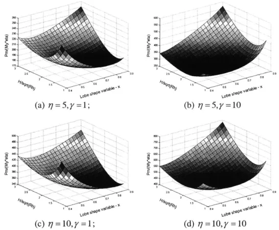
2-9 Surface plot of normalized dimensionless crushing force with respect to the shape variable and the dimensionless half wavelength for different radius to thickness ratio q and hardening to yielding ratio y ... 43
2-10 Corresponding contour plot of normalized dimensionless crushing force with respect to the shape variable and the dimensionless half wavelength for different radius to
thickness ratio q and hardening to yielding ratio y ... 44
2-11 The relationship between effective crushing distance and strain hardening modulus to yield stress ratio y ... 45
2-12 The relationship between dimensionless half wavelength and strain hardening to yielding ratio y ... . 46
2-13 Normalized dimensionless crushing force versus hardening to yielding ratio y ....46
2-14 Dimensionless effective crushing distance versus radius to thickness ratio...47
2-15 Dimensionless optimizing wavelength versus radius to thickness ratio...47
2-16 Dimensionless mean crushing force versus radius to thickness ratio...47
2-17 The formation of eccentric chain link model...51
2-18 Partly. deform ed shape in phase 1. ... 52
2-19 Load-displacement history of eccentric chain link model I...54
2-20 Formation of folds of chain link model II (lobes form both inwards and outwards). ... 5 4 2-21 A geometry of the Chain link model 1. ... 55
2-22 Crushing behavior of chain link model H...57
2-23 Comparison of experimentally measured mean crushing force with prediction of various theories ... 58
2-24 Comparison of experimentally measured half folding wavelength with prediction of various theories ... 58
2-25 An instant picture of chain link model 11 at 6=I and the corresponding free body 2 d iagram . ... 5 9 2-26 Deformation of modified chain link model 1...60
3-1 A comparison of the rolled area of Akerstrom and Wierzbicki's model [1977] and Meng et al's model [1983]. Two folds of quarter models are shown...67 3-2 Comparison of two crushed tubes with different wall thicknesses (left) and with equal
w all thickness (right)... 67 3-3 An illustration of rolling process - materials enter from the lower side and exit from
u p p er sid e ... 6 8
3-4 Chain link model for square tube (left). Compared with Akerstrom and Wierzbicki's model [1977] (middle) and the past experimental result from ICL (right)...70
3-5 A quarter model of chain link model for square tube...70
3-6 A quarter model of a lobe at the end of phase 1 of folding process. ... 71 3-7 An unfolded plot of quarter model of square tube. Shaded area is swept by rolling
p rocess...7 2 3-8 Changing radius in an upper half quarter model...72 3-9 Initiation of phase 2 - new bending process in the segment 2. ... 74 3-10 Folding mechanism of phase 2 -partly deformed. ... 75 3-11 Final shape of a quarter fold. Gaps between upper and lower folds are exaggerated.
... 7 5 3-12 Geometry of final shape of lobe - two perpendicular side views...76 3-13 Pyramid for calculate characteristic angles of hinge lines...76 3-14 A plot of the function g(x) in the range of 0.33 < x 1...80 3-15 Relationship between dimensionless mean crushing force and width to thickness
ratio ... 8 1 3-16 Relationship between dimensionless mean crushing force and width to thickness
List of Tables
2-1 Summary on crushing parameters predicted by existing models...32
2-2 Optimized half wavelength predicted by different theories...48
2-3 Various hardening to yielding ratio y collected from past publications...50
2-4 Phases of deform ation. ... 52
2-5 Deformation phases of early buckled chain link model II...60
3-1 D eform ation lines in phase 2 ... 74
Nomenclature
a length of the translational element
al length of cross-section of box column a2 width of cross-section of box column
b length of the rotational element Eb bending energy per fold
E,,, internal energy
Eext external work
E,. membrane energy per fold h wall thickness of circular tube
H half length of folding waves
kb coefficient of bending energy per fold
keff =eff /2H , dimensionless effective crushing distance
kH = H/R, dimensionless optimized half wavelength
kh,0 0 coefficient for average hoop strain
km coefficient of membrane energy per fold
kp coefficient of dimensionless crushing force
m eccentricity parameter
M instantaneous bending moment per unit length
Mo = O-oh2
/4, full plastic bending moment per unit length MY a h2
/4, bending moment per unit length M af bending moment in tensor notation
No = a0h, fully plastic membrane force per unit length
N membrane force in tensor notation
P instantaneous crushing force
P,, mean crashing force, i.e. energy absorbed per unit shortening Pd dynamic mean crashing force
Pm static mean crashing force
r toroidal radius
R current radius
RO initial radius of middle surface of circular tube
tf time duration of developing one fold
V impact velocity in dynamic test
w radial displacement
x =b/H, shape variable for lobe
y = H/gf, dimensionless half wavelength used in optimization a,f8 time-like parameters for determine load-displacement curve
%,A, characteristic angle for eccentric model X unknown parameter set
(5 axial shortening or crushed distance
effective crushing distance, i.e. crushed distance per fold
6 Strain
Eho, hoop strain
slope angle of midpoint of folding element Y = Ea, dimensionless strain hardening modulus
17
=Ih6 rotational angle of rotational elements UO energy equivalent flow stress
U, yield stress
d _(5), time derivative of axial displacement or crosshead velocity dt
Chapter 1 Introduction
1.1 Energy absorbing unit
In the area of crashworthiness, axially crushed thin-walled tube has, for a long time, served as a prototype of energy absorbing devices. Due to its wide-spread use, numerous publications have been focused on the behavior of tubes under static and dynamic compression.
1.1.1 Industrial application
Structural energy absorbing unit has found many industrial applications, in the nuclear and transportation industries. All modem vehicles, such as planes, cars and ships, are all comprised of sheet metal bodies. To prevent from significant life loss in collision accidents, it is of great importance to design and build crashworthy thin-walled structures.
* Aero/astro industry
In 1920', the crashworthiness of aircraft aroused interest in aero engineers for the first time in order to save the lives of pilots when they have accidents. Aero engineers have been designing cockpit structures aiming at minimize the possibility of serious injury of occupants in case of aircraft crash accidents. For this purpose, Jerry Lederer conducted the first true "crash tests" of aircraft at McCook Field, Ohio in 1924 [Waldock, 1997].
In 1960-70', engineers began to be interested in the aircraft impact problem in civilian and military installations. This is mainly because of the safety reason of nuclear power station [Riera, 1968]. At that time, more and more airbases were built close to nuclear power plants. As a result, the nuclear reactors then are facing the potential risk of a hit from a flying jet plane. To prevent the nuclear reactor from careless pilots or other attacks, the shield of nuclear reactor has to be designed stronger enough to protect it from an aircraft impact. This type of studies initiated by Riera in 1968 for the Federal Aviation Administration [Riera, 1968] goes back to safety evaluation of the Three-Mile Island Nuclear Power Plant. Theoretical model for crushing of aircraft structures is desired to
give guideline of reactor shield design. In such kind of aircraft model, the structural resistance of aircraft is obtained by idealizing the fuselage and wings as thin-walled tubes with different shape of cross-sections. Full-scale aircraft crash tests were conducted including the F-4D Phantom fighter [Sugano et al, 1993] and DC-8 carrier [Johnson and Mamalis, 1978]. Several research groups continued this line of research until recently
[Chadmail et al, 1985, Abbas et al, 1995].
Recent September 1 1th, 2001 terrorist attack to World Trade Center in New York City
aroused more attention in the problem of aircraft impact. Wierzbicki et al [2002] and Wierzbicki and Xue [2002] calculated the energy dissipated by the structural members of the tower as well as the aircraft structure. A reconstruction of the whole sequence of event was set up.
The crashworthiness area or energy absorbing unit is also demanded in helicopters to save the pilots' lives during accidents and in spacecraft landing system. There is a patent that use the expansion of thin-walled tubes to absorb the kinetic energy while space craft lands [Ezra and Fay, 1971].
* Nuclear industry
Axial crushing of circular tubes was exploited in nuclear power plants as an emergency shock absorber [Pugsley, 1960]. This is certainly because the high efficiency nature of axially crumpling of thin-walled tubes in terms of energy absorber.
Another important application of energy absorbing material in nuclear industry is the nuclear container. The container used in transport nuclear waste or materials is designed such that the radiator should not be exposed in case of a crash accident. Hence, it is vital to the designer of such type of structures to make the container crashworthy [Adalian, 2001]. To this regard, there are also applications in transport vehicles of dangerous chemical materials.
* Railway industry
The railway industry also concerns about the crashworthiness of trains. To the authors knowledge, the first documentation in history considering light-weighting is published in 1857 by Fay [1857]. Fay's objective is to save dead weight in passenger trains. At that time, his safety thought is really pioneer.
Pugsley [1960] intended to analyze crushing behavior of a realized railway coach. He focused his research on behavior of thin-walled tubes with circular and rectangular cross-sections when subjected to axial load. This study leads to the energy absorbing consideration and weight reduction in railway research. Currently one project in the Impact and Crashworthiness Lab is devoted to the damage of cab cars in train collisions. * Automotive industry
The crashworthiness of structure has been of keen interest to automotive engineers for years. Since Ralph Nader [1965] published his famous book "Unsafe: At Any Speed" on automotive safety, the public began to realize that the auto accident is inevitable and
consideration has to be put at the very beginning of designing a vehicle. In automobile collision, most kinetic energy of the vehicle must be absorbed by the body deformation. In a typical head-on or rear-end car collision, the kinetic energy is mostly absorbed by longitudinal members. These members are of great importance in terms of the passive safety to the drivers and passengers. Therefore, much research was carried out at the component level of body structures to understand the energy absorbing capacity of such members. Automotive engineers are recently aiming at a lighter body than the existing one by 25% and improve the impact durability by 10% [Kim and Lee, 1999].
* Ship building industry
The energy absorbing concept is integrated to ship design ever since the ship collision protection came to engineers' mind. There not only to prevent the life loss of crew and passengers but also to avoid the oil pollution caused by grounding or collision of crude oil tanker. The US Congress passed the Oil Pollution Act, 1990 (OPA 90) in the aftermath of 11 million gallon spill from Exxon Valdez of crude oil in Prince William Sound, Alaska on March 24, 1989 [NOAA, 1992]. There have been in-depth researches conducted in the Impact and Crashworthiness Lab at MIT in the past decade [e.g. Simonsen and Wierzbicki, 1996]. The collision energy in case of tanker collision is usually dissipated by the plastic deformation and fracture of double hull structure. The rupture of outer plate and crushing of the center web absorbs impact energy and prevents the fracture of inner hull and subsequent oil spill.
A related area to ship building is offshore structures. To build offshore structures crashworthy is also an important task for engineers.
* Others
Energy absorbing units also used in other safety related devices and installation. For instance, they are used in the crash barriers of highway, road bridges and offshore structures [Alghamdi, 2001].
1.1.2 Why thin-walled structure?
There are many types of structures that are used as energy absorbing units. There are two reasons which make thin-walled tube one of the most efficient energy absorbing units. One is the easy producibility and the other is the high efficiency in energy absorbing.
On one hand, most modem transportation vehicles are made of sheet metal due to its easy producibility. For example, in auto industry the body-in-white is such a cage that made from spot welded stamped sheet metal. The front longitudinal beam is a typical structure in passenger cars for absorbing crashing energy during front car crash.
On the other hand, thin-walled structures are capable of carrying substantial loads for deflections far beyond their corresponding ultimate or buckling load. In many practical applications, the energy absorption characteristic of compressed members is of keen interest in terms of safety and passenger protection. These members, such as the
longitudinal beam of passenger cars, may undergo very large deflection that exceed by two orders of the magnitude the thickness and become comparable to their structural dimensions.
Besides thin-walled metal structures, other materials are also used to absorb energy. For instance, wood is used in nuclear container [Adalian, 2001], metal foam is used in automotive and aerospace industry and composite sandwich plate is used in automotive industry, etc. However, because of these two advantage, thin-walled structures are most frequently used as energy absorbers.
Many types of thin-walled energy absorbers were studied experimentally, theoretically and numerically extensively in the past years. Among all such thin-walled structures, the most frequently appeared axial compressive member in literature is circular tubes and square tubes. The crushing behavior of these thin-walled structures energy absorbing units have been investigated in the past:
" Circular tubes [Alexander, 1960, Pugsley, 1960 and 1979, Abramowicz and Jones, 1984, Wierzbicki et al, 1992, etc.];
" Square tubes [Meng et al, 1983, Wierzbicki and Abramowicz, 1983, etc.]; * multi-corner columns [Abramowicz and Wierzbicki, 1989];
* "S"-Frame (front side rail structure of automobiles), [Kim and Wierzbicki, 2001, Ohkubo, et al, 1974, etc.];
" honeycombs (hexagonal cell, [McFarland, 1963, Wierzbicki, 1983]); " cones and frusta [Mamalis and Johnson, 1983, etc.].
Various experiments and theoretical analysis have been done in this area to help understanding the collapse behaviors of structures and their energy absorption capacities, and, later, numerical method was also engaged since computer and finite element method was used [Alexander, 1960, Abramowicz and Jones, 1984a, 1984b and 1986]. However, because of the complexity of this phenomenon, the existing publications do not reveal all of the details of the typical axial crushing of thin-walled structures. In the present work, experimental and numerical results pertaining to the crushing behavior of stainless steel and mild steel square columns were reported and compared with that of theoretical predictions.
There are two ways to improve crashworthiness of certain structures. One is to shape the structure so that the structure deforms at a desired mode such that absorbs maximum crashing energy. The other is to use high-strength material, which could be costly sometimes. The first is preferred in almost all applications unless there are limitations of the structure shape.
1.2
Historic note of axially crushing of prismatic tubes
The problem of progressive buckling of tubes under axial compressive load has been the subject of extensive research over the past century. These prismatic tubes are of particular interest is because they are relatively simple in geometry and they are easily isolated from the main frame of vehicle structures to simulate the energy absorbing unit, for instance, the longitudinal beam.
1.2.1 Experimental, theoretical and numerical study
Experimental
The need of design the vertical channels of nuclear reactors and the longitudinal beams of passenger car make this research topic attractive in many industrial applications. Extensive experiments on thin-walled structures were performed over the past century. The experiments were carried out on both full-scale and component scale. A series of full-scale DC-3 aircraft crash test were performed in 1970's [Johnson and Mamalis, 1978]. Later, a full-scale head on aircraft impact of Phantom 4 jet fighter was performed at Sandia National Laboratory [Sugano et al, 1993].
Component scale tests were conducted extensively around the world, from auto manufacturers to academic laboratories, from ship builders to aircraft designers. The most common specimen used was prismatic column. Static and dynamic axial crushing tests are most common for such kind of specimen. Based on numerous experimental observations, researches have been able to classify the deformation modes that are frequently appeared in academic papers.
Column crashing tests were also performed on different materials, e.g. polyvinyl chloride (PVC) material [Meng et al, 1983], aluminum alloy [Andrews et al, 1983] and mild steel [Akerstrom and Wierzbicki, 1977]
(a) Mode classification
Different from the well-known Euler buckling mode for solid bars, hollow tubes displayed several types of failure mode. Andrews et al [1983] conducted axial crushing of 189 tubes with length to diameter ratio of 0.178.754 and diameter to thickness ratio 4-60.6 on Ht-20 Aluminum alloy. He classified the failure modes into seven groups. These modes are (a) concertina; (b) diamond; (c) Euler; (d) concertina and 2-lobe and/or 3-lobe diamond; (e) axisymmetric/concertina; (f) 2-lobe diamond and (g) tilting of tube axis.
Basically, the statically axial crushed tubes may buckle in either overall Euler buckling (global failure) or progressive failure, see Fig. 1-1 left and middle. For static crush test, fracture is usually not observed. However, at high speed impact (impact velocity above 350m/sec) the impact end of the tube may split into several pieces and fractured with petalling [Wang and Lu, 2002], see Fig. 1-1 right.
Figure 1-1. Global failure (left, past ICL test specimen), progressive buckling (middle, past ICL test specimen) and petalling at a speed of 353 m/s (right,
from [Wang and Lu, 2002]).
The global bending failure is an inefficient mode of energy absorption and needs to be avoided in crashworthiness applications. The trend in automotive industry from building bending S-frame in Volkswagen Santana to progressive crushing straight longitudinal beam in modem Honda Accord embodied such understanding in crashworthiness design.
Axisymmetric (concertina or extensional) mode of collapse or non-axisymmetric (diamond or quasi-inextensional) mode was observed for thin-walled prismatic columns made of ductile material [Johnson et al, 1977]. The crushing mode of circular tubes depends mostly on the thickness to diameter ratio. For smaller value of diameter to thickness ratio (D / h <30), circular tube usually develops axisymmetric mode; while for
larger values, non-axisymmetric mode developed [Pugsley, 1979]. Usually, once past the first lobe, the folding process is periodic.
It is also interesting to note that aluminum tube reinforced by an ultralight filler will develop different modes than non-reinforced ones for thicker tubes. Due to the change of the mode, the energy absorbing capacity decreased as the tube was reinforced [Bouchet, et al., 2000]. For the thinner tube, the reinforcement will increase the energy absorbing capacity. It is also noted that the dynamic load may yield different mode from static loaded thin-walled structure when Pian [1960] studied the deformation modes of hemispheres.
The present thesis focuses on the progressive buckling of thin-walled tubes. The global bending, fracture and petalling is out of the scope of the present thesis.
(b) Experiment set up
The axial crush test is used to be static or dynamic. Static test is usually performed on universal testing machine. Fig. 1-2 shows an MTS universal testing machine used at Impact and Crashworthiness Lab at MIT.
Figure 1-2. An illustration of an MTS universal testing Crashworthiness Lab.
machine at Impact and
Dynamic test can be set up in one of the two ways. One is to shoot the specimen onto a rigid wall and measure the reaction force on the wall. This kind of test is performed extensively using gas gun, for example Wang and Lu [2002].
Velocity Measurement
Target Device (LCD) Barr
Ljto o
o
LLI0
-OscilloscopeGas Charge Firing
el Launcher Chamber Piston + Valve
Primer
^Chamnbe
Charge Primer
Projectile Valve Valve
7
--Manifold
Pressurised Supply Bleed
Gas Supply Regulator Valve Nipple
Figure 1-3. Sketch of a gas gun used in structural impact experiment [Wang and Lu, 2002]
The other type of dynamic test is rigid mass impact test, which the striking mass hit at one end of the specimen at a pre-adjusted velocity. Gas gun is sometimes used in this kind of test, but more often, these tests was performed on drop tower or pendulum, since these two test facilities are able to utilize large amount of potential energy of the striking mass. One kind of such test is drop tower test, which is performed extensively in Impact Center at Liverpool university [Abramowicz and Jones, 1984]. For drop tower test, the impact mass hits the specimen vertically. And the other kind of mass impact test is pendulum test, which the mass hit the specimen horizontally [Ohkubo et al, 1974], see Fig. 1-4 right. Both of these tests utilize the gravity to accelerate the impacting mass.
Steel cable
Vertical guides
ID carriage
PC Charge amplifier Slider block
-impactor
Digital oscilloscope TEST
C
DC power supply Diod WElGAHT
Foam specimen Triggerinig unit
Figure 1-4. Sketches of drop tower test (left) [Shim et al, 2002] and pendulum test apparatus (right, from [Ohkubo, 1974]).
* Theoretical
Design needs
Why we need theoretical model? In industrial application such as automotive design, designers are interested in get an estimate on the energy absorbing capacity at the initiate stage of a design phase. The car body is idealized by a nonlinear spring-and-mass system [Kamal, 1970] to carry out a collision response calculation of the automobile. For such kind of research, component level experiments were carried out to obtain the parameters of the units that are involved in car collision. However, an analytical method is more preferable for its ease to apply at the creative platform designing stage, at which stage prototype is extremely costly, and many times unavailable. This analytical method will provide a rational basis for the design of more efficient energy absorbing structures and lend more confidence in later detailed design stage.
To perform an overall evaluation of crashworthiness of auto body structures at the preliminary design stage, a hybrid method of the above mention multibody dynamics and structural crashworthiness analysis is required. At this stage, no experimental sample is available or is generally too expensive. A detailed finite element model is also unsuitable since they require large amounts of material and geometrical data. Hence, the hybrid methodologies are mostly common used by the industry for crashworthiness design of conceptual models [Ambrosio, 2001].
Overview
The problem of progressive buckling of tubes under axial compressive load has been the subject of extensive research over the past four decades. The early work by Alexander [1960], McFarland [1963], Pugsley and Macaulay [1960], Pugsley [1979], Abramowicz and Jones [1984b, 1986], among others, was aimed at predicting the average force level and energy absorption capacities of hollow columns. Later, Mamalis et al [1988], Wierzbicki and Bhat [1986] and Wierzbicki et al [1992] and Grzebieta [1990, 1991]
pioneer work, various kinematic models were established to make this complex phenomenon convenient for theoretical analysis.
Alexander [1960] built the theoretical model of axisymmetrically collapsed circular tube and, at the same time, Pugsley and Macaulay [1960] developed a basis for analytical solution for non-axisymmetrically collapsed circular tube and later studied by Johnson et al [1977]. McFarland [1963] developed a kinematically admissible model for axial crushing of honeycomb. And Ohkubo et al [1974], Abramowicz and Jones [1984a] Wierzbicki and Abramowicz [1983] and Abramowicz and Wierzbicki [1989] developed models for axial crushing of square or rectangular cross-sectioned columns. These researches greatly advanced the theoretical basis of crashworthiness analysis.
* Numerical
The finite element method was applied to the analysis of crashing behavior of structures soon after its successful application in small deflection problems. Simulations were performed both on component level, for example the longitudinal girder for a passenger vehicle, to substructure level [Kim et al, 1999], for example the front part of car body, to a full-scale level, i.e. a whole vehicle or helicopter.
The Finite Element Method has played an important role in car crashworthiness analysis. It was first used in 1973 for aircraft structures [Khalil and Sheh, 1997]. The first application of explicit FE technology to crashworthiness of actual vehicle structure appears to be attempted by ESI to simulate Volkswagen Polo in 1985 [Khalil and Sheh, 1997]. This line of full-scale research is continued and has been steadily rising in the past years. A brief chart of evolution of crash simulation method in automotive industry is shown in the Fig. 1-5.
2000 8 CAE-driven
vehicle design Reduction of
'96 protowyes.
Essential ject decisions based on simula on results
'91
W First productive results
' Feasabilitystudies
Figure 1-5. Evolution of crash simulation method. [Blumhardt, 2001]
Commercial codes were also introduced to study crashing behavior of typical structures, such as closed-hat cross-section beams [Mikami and Sato, 1999].
Nowadays, the main commercial codes, such as PAM-CRASH [Kim and Wierzbicki, 2001], LS-DYNA [Xue et al, 2000], ABAQUS/Standard [Karagiozova and Jones, 2001], ABAQUS/Explicit [Wang and Lu, 2002] are used to simulate structural crashing behavior by various authors.
There has been increasing demand for lightweight in auto body design. Hence, to optimize the thickness of the sheet metals, the design of members and member connections is of great importance. The front longitudinal member should be designed such that it is neither too soft to be inefficient in energy absorbing in a car crash, nor too stiff to intrude the compartment extensively. There has been extensive parameter study using numerical method in automotive industry. For instance, Reid [1996] performed a series of numerical test using LS-DYNA on auto midrail and proposed the guideline for select shell thickness and material property:
" For a specific stress, a 10% change in thickness results in a 14% change in energy
absorption;
" For a specific thickness, a 10% change in stress results in a 7% change in energy
absorption.
The problem of axial crushing of thin-walled tubes is such a classical problem that recently it became a benchmark problem for validation of non-linear finite element code. [Otubushin, 1998]
1.3 Typical crashing curve of thin-walled tubes
A typical crashing curve of circular tubes is shown in Fig. 1-6. Concertina mode
235-30
z 5 foLds starting at bottom of tube
25 1 4 compLete foLds 20-10, 5 - Specimen 6 in (b) o 5 IO 15 20 25 30 5 40 45 50 55 60 65 AxidL dispLacement (mm )
Figure 1-6. Experimental load-displacement curve for an axially symmetrical progressive buckled circular column. [Andrews et al, 1983]
In the above figure there are three stages of axial crushing of circular tubes. The first stage is the pre-buckling phase. In this stage, the reaction force goes up to the initial peak. This initial high peak of load is closely related to the static/dynamic buckling load of the tube. In this stage, only homogeneous axial shortening is occurred. There is no fold is formed and no significant radial movement of the shell material. In the second stage, most of shortening is happening in this phase. The tube displays a periodical wave of deformation. At the end of this stage, the tube is significantly shortened all the way to bottoming-up. In the final stage, the already impacted tube is further crushed. Since the crushed tube is almost solid, the reaction force increases quickly and soon beyond the range of the load cell. This is last almost vertical line in the load-displacement history. In this thesis, the most interest is put on the second stage of periodical phase.
From the above figure, several feature of the curve is observed for the second stage. These features are:
(a) Once passed the initial peak, the load fluctuates around a certain mean value of crashing force, which is called the mean crushing force.
(b) There are alternating peaks after the initial peak, at fixed intervals.
(c) The wavelength of the folds is essentially not changed during the progressive folding process.
In the present thesis, a novel kinematic model for analyzing the crushing behavior of circular tubes after the initial peak is presented.
1.4 Mechanics of crash deformation
Several deformation mechanisms are frequently used in energy absorbing unit. These mechanisms can be divided into two groups:
" collapsible modes and " non-collapsible modes.
The collapsible modes include axial crushing, lateral indentation, lateral flattening [Reid, 1983], inversion [Miscow and Al-Qureshi, 1997] and splitting. Alghamadi [Alghamdi, 2001] systematically reviewed the collapsible impact energy absorbers. The non-collapsible modes include lead extrusions or tube expansions.
In the scope of structural crashworthiness, several deformation mechanisms are frequently involved in common structural crushing, for example,
" Membrane deformation " Bending deformation " Rolling deformation and
" Fracture (out of the scope of present thesis).
Alexander [1960] and Pugsley and Macaulay [1960] first provide theoretical analysis on the axisymmetrically and non-axisymmetrically crushing of circular tubes. They
attributed the energy dissipation to membrane and bending deformation. The membrane energy is dissipated through the plastic hoop strain between plastic hinges and the bending energy is dissipated solely by the rotation of the concentrated plastic hinges, which connects the straight elements.
To the best of author's knowledge, McFarland [1963] firstly proposed the theoretical model for axial crushing of non-axisymmetric structure. The purpose of his analysis was to provide a rational means by which hexagonal cell structures can be designed for use as energy absorbers. His idea of panel element was later used by many other researches. Later, Wierzbicki [1983] continued this line of research on the crushing of honeycombs.
Following McFarland's procedure, Ohkubo et al [1974] established a kinematic model for closed-hat cross-section column. He distinguished two mechanicsms of energy dissipation: the rolling deformation and the bending deformation.
It is known that square columns can buckle in different modes, i.e. symmetric and non-symmetric. From numerous experiments, it becomes evident that the geometrical imperfections have little effect on the mean crushing force of certain crushing mode. In progressive buckling, the structures are already buckled and are under large post-buckling deformation. As long as the initial buckling force is not of interest, Xue et al [2000] amongst others showed numerically that the geometrical imperfection are only important at the early stage of buckling to determine the collapse mode.
Abramowicz and Jones [1984a and 1986] classified the modes into four types: symmetric (or non-extensional) collapse mode, asymmetric mixed collapse mode A, asymmetric mixed collapse mode B and extensional collapse mode. Akerstrom and Wierzbicki [1977] extend Ohkubo's solution to the axial crushing of rectangular cross-section columns. They derived an expression for not only the mean crushing force, but also instantaneous crushing force.
Wierzbicki and Abramowicz [1983] have put the crushing mechanics of thin-walled structures on firm theoretical basis. They developed a consistent collapse mechanism of a corner element consisting of 9 sections: 4 trapezoidal elements, 2 cylindrical elements, 2 conical elements and one toroidal element, see Fig. 1-7 (a). In their deformation field, the rolling radius was treated as an unknown and was determining through the minimization procedure. Abramowicz and Wierzbicki [1989] extended their solution to arbitrary angled multi-corner elements.
SC L (b) (a) 0 Vt (c)
Figure 1-7. Crushing mechanism (a) a 9-section corner element; (b) global geometry of crushing mechanism of a corner element; (c) plastic flow of a metal sheet through a toroidal surface. [Wierzbicki and Abramowicz, 1983] Abramowicz and Jones [1984a and
[1983] symmetric collapse solution to extensional corner element suitable for also developed.
1986] extended Wierzbicki and Abramowicz's the four collapse modes they classified. An analyzing asymmetric and extensional mode is
Energy dissipation rate
From the principle of virtual work, the rate of energy dissipation in the crushing process equals the rate of external work exerted, i.e.
text =Ekin -(1-1)
In the axial crushing of thin-walled tubes, the rate of external work is
Eext= P5 (1-2)
where P is the instantaneous force and S is the crosshead speed.
Consider the continuous and discontinuous velocity fields, see [Wierzbicki and Abramowicz, 1983 and 1989, Abramowicz and Wierzbicki, 1989] the internal energy basically consists of a bending part and a membrane part. In tensor notation, this is
Ma +ka +Na/iAaIS+ JMOWL, (1-3)
s
L
where S denotes the deformation area and L denotes the discontinuity line in rate of rotation (hinge lines), 2A is the rate of extension and ka6 is the rate of curvature, M a and Na is the bending moment and membrane force defined in the continuously deforming zone along the current variable thickness,
M a" = 2 zdz (1-4)
and
Naf= 2 JadZ. (1-5)
The first term in the right hand side of Eq. (1-3) represents the dissipation due to a continuous change of curvature in the strip and the second term describes the discontinuous dissipation at the stationary or traveling hinge lines.
Minimum principle
According to Hill-Markov's theorem of plasticity, the best deformation direction should be in the direction of the energy gradient. Let Z be the deformation parameter set, the internal rate of energy dissipation is extremized in the deformation direction, i.e.
a f.dxV =0. (1-6)
It should be noted the extremizing parameter set Z is based on the instantaneous current configuration and is changing with time. In other words, the deformation direction is history dependent.
It is observed that the deformation parameters undergo only slight changes during the crushing process, the global average over the complete folding process is then used as a substitution of the instantaneous equilibrium, i.e.
+-fda tV =0 (1-7)
where a is the time-like process parameter changes from 0 to af when time goes from
0 to the end of duration tf and V denotes the material volume. This means the best
average values of the parameter set X is obtained by extremizing the total plastic work. Noting the mean crushing force is proportion to this total work, the best deformation parameters were found by minimizing the mean crushing force. This is the postulated used by Alexander [1960]. However, there seems lacking of a general proof of this global minimum principle [Abramowicz and Wierzbicki, 1989]. An in-depth discussion could be found in Abramowicz [1996].
Chapter 2 Chain Link Model for Circular
Tubes
2.1 A brief review of the existing models
2.1.1 Geometry and assumption
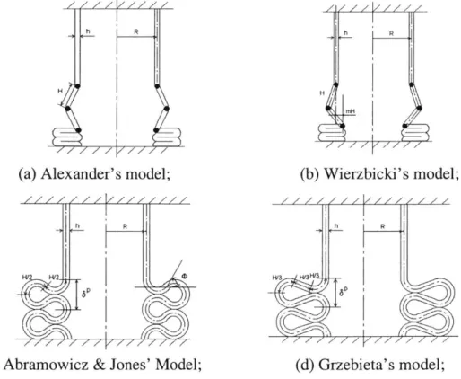
In the present thesis, the well known axisymmetric or concertina mode is studied theoretically. Previously, various kinematically admissible models were established in the past. The geometries are shown in Fig. 2-1.
h/
H
(a) Alexander's model;
(c) Abramowicz & Jones' Model;
h R H (b) Wierzbicki's model; h R F'3 HF3 (d) Grzebieta's model;
Two modified kinematic models are presented. Several assumptions firstly made by Alexander [1960] were kept for various models. These assumptions, which are also adopted in this paper, are:
(a) The meridional length of the shell remains constant during the folding process. (b) The length of folding wave remains constant throughout the deformation process. (c) The length of the folding wave is determined from the postulate of minimum mean crushing force.
(d) The initial axial shortening phase is not considered and it does not change the diameter of the tube.
(e) The folding process ends when the lobe contacts with the previously formed fold and the next fold begins to develop.
In addition, it was assumed that the bending in plastic hinges is uncoupled from the stretching or compression of material between hinges. Using the principle of virtual work, Alexander was able to predict the optimized wavelength and the mean crushing force with a fair degree of accuracy. Alexander's procedure was the backbone of later studies.
2.1.2 Alexander's model
The first kinematically admissible model was established by Alexander [1960], see Fig. 2-1(a). Alexander used the von Mises yielding criterion and assumed that the tube is
in a state of plane strain, the direct stress will be raised to
2 - (2-1)
where a- is the yield stress. The corresponding bending energy and membrane energy are calculated from
8rcM
E=
(FrRe
+ H) (2-2)and
87TH2M
E,,= h '.(2-3)
where = -=-,h2 is the fully plastic bending moment per unit length.
4
In later publications the strain hardening effect was included through the concept of the energy equivalent flow stress o, [Abramowicz and Jones, 1986, Wierzbicki et al, 1992]. Using the flow stress for both bending and membrane deformation, Alexander's prediction of the mean crushing force is
-22.27 - + 6.28 (2-4)
MO h
Hh
-=1.77 . (2-5)
RO 2R
0
The constant of 6.28 resulted from the change of hinge length in outward buckled columns. Alexander [1960] also predicted the constant of -6.28 for inward buckled columns. In practical, this constant is relatively small compared with the dominant term
22.27 in Eq. (2-4). It was ignored in subsequent literature [Wierzbicki, 1992].
h
Alexander model fails in predicting the effective crushing distance and underestimates the magnitude of mean crushing force by about thirty percent. This is mainly because this model does not depict the realistic shape of fold. Also, the rising phase of the load-displacement curve is too abrupt and its peak is too sharp. Adjacent elements in this model are at zero degree at the end of folding. Still, this simple model has some value for design purposes and the analysis illustrates the general approach which was employed for studying this complicated phenomenon.
2.1.3 Abramowicz and Jones' model
The mean crush force and the folding wavelength are given respectively by
P R = - 25.23 0 +15.09 (2-6) MO h and H h -=1.84 . (2-7) RO 2R0
The dimensionless effective crushing distance, which is the ratio of crushed distance to the original length per fold, was assumed to be 0.75 for columns with 2R0 = 46.14.
h
To satisfy the slope continuity condition of the folding wave at the point of curvature reversed, see Figure 1(c), the slope of the midpoint of the curved element <D
has to be _'. The corresponding dimensionless effective crushing distance is 0.809.
3
Hence, the crushing behavior can be derived for this superfolding element.
Considering both strain hardening effect and the influence of wall thickness, the dimensionless effective crushing distance for concertina mode of cylindrical tubes derived by Abramowicz and Jones in Ref. [7] is
6
kef
- ff -0. 8 6-0.5 86h
2H 2RO
Abramowicz and Jones' model introduces the curvature of the lobe and thus predicts dimensionless effective crushing distance with good agreement. This model accurately predicts the mean crushing force over a wide range of radius to thickness ratio
especially when 10<Ro/h<30. However, Abramowicz and Jones's study is based on the final deformed shape of lobe and does not predict the load-deflection history.
Wierzbicki and Bhat [1986] put forward a moving hinge solution for the folding formation of this model. In this solution, a concept of traveling plastic hinge is introduced. Each folding element has two curved parts with fixed radius and a middle straight portion. The straight portion turned to curvature when the folding develops. The cyclic softening and stiffening phase of load-deflection character can be predicted correctly by this solution.
Grzebieta [1990, 1991] proposed another modification of for the Alexander and Jones' model. In his solution, a continuously variable curvature was introduced. The curvature of the entire length of folding wave is formed at the beginning of buckling phase. The curvature increases progressively to the final shape as folding process progresses. The load-displacement curve of this model can also be determined by the equilibrium equation.
2.1.4 Wierzbicki's eccentric model
The eccentric model is an important modification to Alexander model. By introduction of the eccentricity parameter, m, a more realistic inward/outward folding can be described. Wierzbicki et al, [1992] used the flow stress to calculate MO and the length of each fold is assumed to be 4H, which is 2H use by Alexander [1960]. If the fold length is denoted as 2H and neglecting the constant term in Eq. (2-4), the eccentric stationary hinge model predicts the same mean crushing force and optimized half wavelength of Alexander's model, i.e.
P 2 " = 22.27 -- (2-9) MO h where Hh =1.77 - (2-10) RO 2R 0
This means the mean crushing force is independent of the eccentricity. It is also notable that the eccentric model degenerate to Alexander model when m=0 (outward) or
m=1 (inward).
Comparing with the experimental data, Wierzbicki et al's continuous model shows good agreement with experiment in both the mean crushing force and load-displacement history. The alternating pattern of higher and lower peaks observed in many experiments is correctly simulated by the eccentric model. This model also predicts finite value of the load peaks, which is not achievable for Alexander model.
It is interesting to note that there is a strain reversal in the eccentric model, provided the folding process extends over four half waves. The effect of eccentricity has been proved to be important [Wierzbicki et al, 1992, Singace et al, 1995, Singace and
El-Sobky, 1996, Avalle and Belingardi, 2002]. Singace et al [1995] proposed a theoretical value of m=0.65, which is consistent with experiments [Singace and El-Sobky, 1996]. Avalle and Belingardi [2002] further included the thickness variation due to the circumferential stretching at the fixed hinges.
Wierzbicki et al [1992] also presented continuous deformation eccentric model, which predicts the mean crushing force and the half wavelength are
= -31.74 (2-11) M o h and H h
-=
2.62 -. (2-12) R 2RThe concept of Superfolding Element (SE) [10] is used in this model. Superfolding element is quite general mechanism and can simulate the transition zone of various thin-walled structures.
2.1.5 Grzebieta's model
Grzebieta introduced a straight element in the middle with equal length to the curved elements at the ends, see Fig. 2-2. The mean crushing force is not given explicitly for Grzebieta model [1990, 1991]. The load-displacement curve can be derived by the Alexander's procedure.
Figure 2-2. Fully crushed shape for Grzebieta model.
The crushed shape of Grzebieta's model is more flat than Abramowicz and Jones' model. The effective crushing distance is not explicitly shown in [Grzebieta, 1990, 1991]. The characteristic angle, 6 in Fig. 2-2, can be found from the equation
6= 2cos--z, (2-13)
sin 0 2 and the dimensionless crushing distance is
keff = sin 6 (2-14)
3(2cos6 -1)
The solution for Eq. (2-13) is 0.425 or 24.335' and the dimensionless effective crushing distance to be 0.833. Thus, compared with Abramowicz and Jones' model, Grzebieta model predicts a larger dimensionless effective crushing distance. Based on observation of experimental result, the effective crushing distance increases as 2R / h
increases [Abramowicz and Jones, 1984b, 1986], also see equation (8). Obviously, the Grzebieta's model more accurately predicts the crushing behavior of tubes with larger
2R0 /h. More recently, Gupta and Velmurugan [1997] extended Grzebieta's model to an
eccentric solution of the same lobe shape.
2.1.6 Summary
The relationship between mean crushing force and the ratio of radius to thickness predicted by above models is parabolic. By re-examination the previous models for concertina collapse, it is found that the dimensionless mean crushing force is proportion to square root of radius to thickness ratio. And the optimizing half wavelength is normalized by radius and is reciprocal to the square root of radius to thickness ratio. If normalize this half wavelength with respect to thickness, then the non-dimension half wavelength will also proportion to the square root of radius to thickness ratio. It is convenient to define a variable of the square root of radius and thickness, i.e.
7 = . (2-15)
h
Consequently, the mean crushing force and the optimizing half wavelength can be written in an elegant way. These values for existing models are summarized in Table 2-1.
Table 2-1. Summary on crushing parameters predicted by existing models.
Model Mean crushing force Optimizing half wavelength
P H
Alexander (1960) ' - 31.487 -=1.257
M 0 h
Abramowicz and Jones P' = 35.681 =1.30
(1984) M h
=4.8 H
Wierzbicki et al (1992) M- h44.89r -=1.85r
M0 h
2.2
Chain link model I
The objective of the present research is to derive a closed-form solution for the load-displacement relationship with periodic peaks and valleys, as it is observed in the static and dynamic crushing tests. In order to achieve this goal, a new chain link model is introduced which captures all main features of the actual loading process. An important feature is this model is a more realistic representation of the effective crushing distance which depends on the radius to thickness ratio and on material properties.
2.2.1 Formation of folds
In chain link model, the folds are formed in the following way, see Fig. 2-3.
One lobe
5 5
'0
I®'
Figure 2-3. Formation of folds for chain link model I (buckling forms outward). (In the figure, numbers denote hinges and numbers in circles denotes elements.)
2.2.2 Assumption
Because of larger number of degrees of freedom, additional assumptions are made to simplify the analytical solution. However, the purpose of the paper is not trying to calculate the crushing behavior of circular tubes using very fine mesh as was used in finite element analysis, which introduces thousands of degrees of freedom. Therefore, assumptions are still made in this paper to make this problem mathematically tractable.
Each lobe consists of four straight elements and five hinges, see Fig. 2-3. The first and last hinge is shared with the previous and the following folds. The assumptions are: (1) Only one lobe is forming at a time, thus three elements are moving at a time during
crushing.
(2) The four elements of each lobe are of two kinds, i.e. translational elements - element 2 and 4 - and rotational elements - element 1 and 3. Element 2 moves parallelly to the central line, which has homogenous hoop strain. Element 4 stays at the same place in the folding process and, hence, has no strain and dissipates no membrane energy. It is observed in experiments that the lobes are vertically symmetric. This requires the two rotational elements to have the same lengths.
(3) Exact contact condition. Each fold completes its deformation when a contact is
2 3 I j2 EZ 4~ 3 6 5 8 97 4 6 7 8 '9 I
developed with the previous fold. The contact between folds and within one fold and the completion of the consecutive element occur at the same time. This means the hinges 5 and 8 contact each other when hinge 6 contacts hinge 3. This requires the two translational elements to have the same lengths.
However, there is no need to assume the two types of elements in a lobe have an equal length. Here, the length of translational and rotational elements are denoted as a and b, respectively. The shape of the lobe is distinctively determined by these two variables a and b.
2.2.3 Geometry
A completed deformed fold is shown in Fig. 2-4.
b
Figure 2-4. Geometry of one fold of chain link model I.
It should be noted that in this chain link model, the rotational angle of the two rotational elements are greater than -1. As shown in Figure 4, the crushed shape has the
2
maximum folding angle:
. a---h 7t
M = arcsin +-. (2-16)
2b 2
Neglecting the wall thickness, the maximum folding angle is
M = arcsin-+-= arcsin -x +- (2-17)
2b 2 2x 2 For folds having a = b, 6. - 2g
3
2.2.4 Effective crushing distance
The ideal geometry shown in Figure 4 gives an effective crushing distance
S ff=2b+a-h . (2-18)
The length of folding wave, which is 2a+2b here, is denoted as 2H in Alexander model, and later used in many papers. Thus, a + b = H is used below for convenience
and compatibility with the established models. To simplify the problem, the wall
b b
thickness is disregarded in the following procedure. Denote x b - as a lobe
a+b H a
shape variable, thus - = 1- x and the dimensionless effective crushing distance is
H
keff 45eff 2b+a 1+x
2(a + b) 2(a + b) 2
The exact contact assumption limits the range of the rotational element length, b, i.e. 0.333 b/H 1. Abramowicz and Jones found experimentally that the effective crush distance in static and dynamic tests [Johnson et al, 1977] ranges approximately from 0.67 to 0.80. This range was also observed by other authors [Abramowicz, 1986, Abramowicz, 1983, Ohkubo, 1974]. Abramowicz attributed the variation of effective crushing distance predominantly to the plastic hardening properties of the material [Abramowicz, 1983]. Based on this result, Abramowicz and Jones proposed the theoretical value of dimensionless crushing distance, see equation (8). Teng [2001] used a power law strain hardening model to predict effective crushing distance for metal fiber. Teng obtained that the dimensionless effective crushing distance ranges from 0.99 to 0.85 as the exponential strain hardening modulus varies from 0.01 to 1.0.
2.2.5
Bending energy
Each hinge in Alexander's model has a final folding angle of 180 degree. Ohkubo [1974], among many others, pointed out that based on experimental observation the bending angle exceeds 180 degree while folding. Thus, the bending energy is underestimated in Alexander model. Chain link model deals this problem quite well. In chain link Model I there are four active hinge circles at any time, each has the same rotation rate 0. Disregarding the change in radius of hinge line, the energy dissipation rate at the four active stationary hinges is
Eb= 8gROMO O56 . (2-20)
The bending energy for each lobe is obtained by integrating Eb with respect to time over the duration of the folding cycle 0 - tf, or by integration with respect to the rotation angle 0 in the limits 0, 6.:
E =8gR0MO0O. =4gR0MO ; + 2arcsin -a- =kb(42RMO) (2-21)
(2b)]
where
k i2 .(a~ 2 (1-x
kb =1+--arcsin -- =1+ 2 arcsin -x (2-22)
is t2b) IT o 2x
![Figure 1-3. Sketch of a gas gun used in structural impact experiment [Wang and Lu, 2002]](https://thumb-eu.123doks.com/thumbv2/123doknet/14220909.483677/19.918.153.733.546.704/figure-sketch-gas-used-structural-impact-experiment-wang.webp)
![Figure 1-4. Sketches of drop tower test (left) [Shim et al, 2002] and pendulum test apparatus (right, from [Ohkubo, 1974]).](https://thumb-eu.123doks.com/thumbv2/123doknet/14220909.483677/20.918.196.738.101.345/figure-sketches-tower-shim-pendulum-apparatus-right-ohkubo.webp)
![Figure 1-5. Evolution of crash simulation method. [Blumhardt, 2001]](https://thumb-eu.123doks.com/thumbv2/123doknet/14220909.483677/21.918.167.691.676.986/figure-evolution-crash-simulation-method-blumhardt.webp)