Carbon Nanotubes: A Study on Assembly Methods
by
Lisandro E. Quifiones
SUBMITTED TO THE DEPARTMENT OF MECHANICAL ENGINEERING IN PARTIAL FULFILLMENT OF THE REQUIREMENTS FOR THE DEGREE OF
BACHELOR OF SCIENCE IN MECHANICAL ENGINEERING AT THE
MASSACHUSETTS INSTITUTE OF TECHNOLOGY
June 2008
©2008 Lisandro E. Quifiones. All rights reserved.
The author hereby grants to MIT permission to reproduce and to distribute publicly paper and electronic copies of this thesis document in whole or in part
in any medium now known or hereafter created.
Signature of Author:
Department of Mechanical Engineering May 9, 2008
Certified by:
& ,- -'
Carol Livermore Professor of Mechanical Engineering Thesis Supervisor
Accepted by:
Profess(
MASSACHU SETr S INS E
OF TECHNOLOGY
LAUG
1 2008
LIBRARIES
SJohn H. Lienhard V. )r of Mechanical Engineering ergraduate Thesis Committee
Carbon Nanotubes: A Study on Assembly Methods
by
Lisandro E. Quifiones
Submitted to the Department of Mechanical Engineering on May 9, 2008 in partial fulfillment of the requirements for the Degree of Bachelor of Science in
Mechanical Engineering
Abstract
The urgent stipulation is to manufacture CNTs of desired properties and dimensions. The heart of this
yearning lies in understanding the growth and assembly methods of CNTs, which are not yet clear. In this study, hence, we concentrate on the synthesis and assemblage, pointing out the parameters, issues, and limitations of the available techniques. While there have been many interesting and successful attempts to grow and assemble CNTs by various methods, this study focuses on the conventional growing techniques and proposes unconventional assembly methods.
Thesis Supervisor: Carol Livermore Title: Professor of Mechanical Engineering
Acknowledgements
I would like to thank my thesis advisor, Prof. Carol Livermore, for proposing this particular venture and for guiding me throughout the course of this thesis.
Contents
List of Figures 5
List of Tables 6
1 Introduction 7
2 Potential with Limitations 8
2.1 Behind the Motivation ... 9...
3 Growing Methods: Production for Assembly 11 3.1 Arc-Discharge Method ... ... 11
3.2 Laser-Ablation Method ... 13
3.3 Chemical Vapor Deposition Method...15
4 Pre-Assembly Techniques and Applications 17 4.1 Molecular Combing: Deposition and Alignment ...18
4.2 Nanoconnection via HREBL ... 19
4.3 Alignment by Nanopelleting ... 20
4.4
Densification from Vapor Infiltration ...
21
4.5 Densification for Interconnects ...
... 22
5
Proposed Assembly Methods
23
5.1 Interfacial Adhesion and Void Bridging...24
5.2 Yarning by Spinning ... .. 26
5.3 Overlapping Configurations ... 27
6 Future Considerations 30
List of Figures
1 Vertically aligned CNTs. Nanotubes can vary in size, and the ones shown are about 5 nm across. Each tube is about 250 tm long, and they can be spaced as little as 5 nm apart.
7
2 Two basic morphologies of CNTs with corresponding schematic. (a) Transmission electron microscope (TEM) image of a multiwalled carbon nanotube. (b) Schematic of a multiwalled
nanotube. (c) TEM image of a bundle of walled CNTs. (d) A schematic of a bundle of single-walled nanotubes.
9
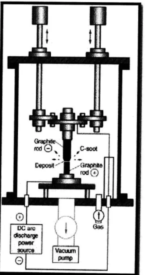
3 Schematic diagram of CNT formation apparatus by the arc-discharge method.
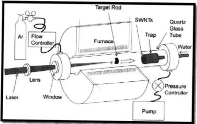
12 4 Schematic diagram of the laser-furnace apparatus.
13 5 Schematic diagram of a CVD setup (a). Probable models for CNT growth (b).
15
6 Atomic Force Microscope (AFM) observation after molecular combing. A single CNT is clearly visible aligned with the direction of the pre-defined microelectrodes.
19
7 Scanning Electron Microscope (SEM) observation of a sample after nanoconnection (a). AFM
observation of the same sample (b).
20 8 Trimmed CNTs via CMP process: (a) A side view of planarized CNTs. (b) An oblique view of the planarized CNTs.
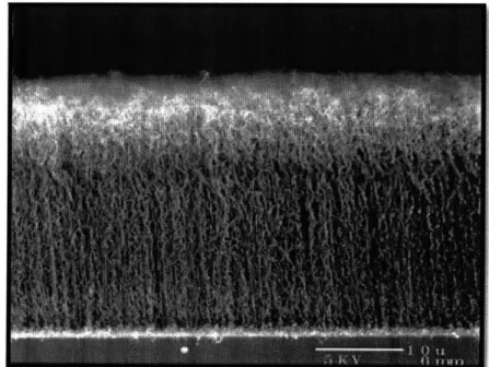
21 9 SEM photographs of ACNTs.
22 10 CNT bundles (a) before and (b) after densification.
23 11 An individual carbon nanotube is attached to the end of an AFM probe and embedded within a solid epoxy polymer. Separation of the probe from the polymer causes pull-out of the nanotube (right) with the force recorded from the bending of the AFM cantilever.
25
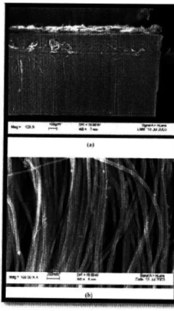
12 SEM images, at two different magnifications, of a carbon nanotube yarn in the process of being simultaneously drawn and twisted during pinning from a nanotube forest outside the SEM.
27
13 Schematic illustration of the procedures for fabricating multi-component, interposed CNT micro-patterns by dry contact transfer followed by region-specific adsorption.
28 14 Schematic illustration of CNT "forests" (meshed surface) grown along the steps of a substrate.
List of Tables
1 The properties of single-walled carbon nanotubes.
1 Introduction
Carbon nanotubes (CNTs) are the motivating agent for recent advances in nanotechnology; they have exceptional mechanical and electronic properties that make them the most-wanted material for new generation electronics. Discovered in the 1990s, carbon nanotubes are stronger than most metals and as flexible as some plastics. They conduct heat and energy better than most known materials and can be manufacture from regular raw materials such as methane, ethylene, or carbon monoxide. In recent years, CNTs (figure 1) -thin tubes of carbon atoms that have remarkable characteristics because of their unique structure-have come forward as a promising material that could reform manufacturing industries, especially the nano-electronics industry. Almost weekly, new potential applications of carbon nanotubes are identified in the fields of chemistry, biology, and material science, inspiring scientists to give serious thought into these thin tubes with escalating interest.
Figure 1. Vertically aligned CNTs. Nanotubes can vary in size, and the ones shown are about 5 nm across. Each tube is about 250 ptm long, and they can be spaced as little as 5 nm apart. [ll
Considerable research progress during the last few years has been achieved; however, numerous limitations of carbon nanotubes are still to be conquered. Incompatibility with chemical and biological environments, insolubility in the majority of organic and aqueous solvents, and growing restrictions are among the technical limitations of CNTs. Provided that these constraints can be
surmounted, CNTs could be implemented within widespread applications, such as molecular electronics, drug delivery, and meta-materials design.
In light of previous experiments on the growth of CNTs, unstable growth locations and disoriented structures are the main constraints found. Once grown, assembly issues arise from restrictions in overlaying nanotubes in a way that the final structure enables for integral arrangement at higher densities. Having low concentration densities at a given growth location avert from unifying a solid network of CNTs which could potentially be used in the conception of new generation textiles.
2 Potential and Limitation
Controlling the geometry in the growth and assembly of CNTs is necessary to reach the many potential applications of these materials. To have strong nanotube fibers, strong nanotubes are needed from start; appropriate growth methods are discussed in the following subsections. Since nanotubes are very strong, they could make well-built fibers if they were assembled into ordered strands; techniques for creating ordered fibers from CNTs will be explored.
CNTs contain unique mechanical properties that enable them to store large amounts of energy for their size. These properties include high strength that allows for high strains and high Young's modulus for enhanced elasticity. Given that energy density is defined as the product of Young's modulus times the square of the failure strain, this enables the storage of energy with high energy density in CNTs. Nonetheless, individual nanotubes are very small in size. Since storing macroscopically useful amounts of energy requires a lot of carbon nanotubes, it is useful to assembly CNTs into arrays that have properties that are similar to those of an individual nanotube. This is a noteworthy technical challenge that calls for both reliable growth techniques to manufacture long, defect-free nanotubes and robust methods for assembling them into large arrays with functional properties. This thesis first reviews existing techniques for growing carbon nanotubes and combining them into larger arrays, and then proposes unconventional assembly methods to enable novel arrangements that CNT applications require.
To obtain good strong nanotube fibers, nanotubes must to be combined together in a way that allows the whole assembly to be strong. In other words, the nanotubes must be well-ordered and
close together so that they can interact strongly with each other. This strong interaction will enable applied loads to be transferred from the nanotubes at one end of the fiber to the ones in the middle and then to the ones at the other end of the fiber. Various techniques will be reviewed to accomplish this, such as placing nanotubes in an overlapping configuration or densifying them mechanically. Almost certainly, promising methods will arise from merging many of these techniques together.
2.1 Behind the Motivation
CNTs form two structurally distinct classes. The first to be discovered, multiwalled CNTs (MWNTs), shows a Russian doll-like structure of nested concentric tubes (figure 2a, b). The interlayer spacing can range from 0.342 to 0.375 nm, depending on the diameter and number of shells comprising the tube. The interlayer spacing in graphite is 0.335 nm, suggesting a similarly weak interaction between individual shells in MWNTs.
Figure 2. Two basic morphologies of CNTs with corresponding schematic. (a) Transmission
electron microscope (TEM) image of a multiwalled carbon nanotube. (b) Schematic of a multiwalled
nanotube. (c) TEM image of a bundle of walled CNTs. (d) A schematic of a bundle of
single-walled nanotubes.
[21The second type of CNTs is in the basic form of a rolled-up graphitic sheet-a single-walled CNT (SWNT). During the production, their diameter distribution is relatively narrow, so they often bundle up in the form of crystalline 'ropes' (figure 2c,d ) in which single tubes are held together by van der Waals interaction [3].
; ;
Absence of defects in individual nanotubes enhances their mechanical properties and their potential as structural reinforcements. Rigorous bonds are formed from covalently linked carbon atoms having three nearest neighbors. Tube ends are sealed, with no dangling chemical bonds to weaken the arrangement. The lightweight structure is assembled as an ideal carbon fiber that has the strongest bonds found in nature. Cohesive strength between carbon atoms and high elasticity compared with that of graphite fibers make nanotubes highly resistant to failure under tension.
CNTs are known to have a tensile strength of 50 to 200 GPa, which is at least an order of magnitude higher than conventional graphite fibers [4]. Additionally, calculations of high elasticity and bending stiffness are supported by thermal vibration amplitude measurements of a Young's modulus of over one TPa. In addition, nanotubes are expected to break at very high strain (5 to 20%), and in dynamic simulations they behave like "superstrings." They narrow down to single carbon chains upon application of tension. CNTs also exhibit resistance to distortion from torsional forces, and in many cases the original cross-section of the nanotubes is restored when the load is released. Unlike graphite fibers, which fracture easily under compression, nanotubes under compression form kink-like ridges that relax elastically after loading. Such properties are directly applicable to a variety of engineering structural applications, including high-strength composites and textile weaves.
Table 1 The properties of single-walled carbon nanotube. [5]
Size
Deusity)
Tensile Strength
Yomng's modulus
Current Cawying Capacity
Field EMiss5ion
Heat Transnission
SWNTDiaieter: 03 --
1.8 nm
1,33-1-40
g/cm
40-60 0 Pa 1.2 TPa lIx0 AlcnrPosphor : 1-3 V\a
6-000 W/ntk
Comparison
Elkctr
bioamr: 4-0m
Al 2.7 g/ cm
Steel Alloy: 1-2 GPa
200 GP
Copper Wires: IxliA/'cml Molyennum tip: 50 - 1.00 Vtý
Diamond 3320 Wimk
Table 1 illustrates excellent properties of single-walled carbon nanotubes in comparison with several metals. It is remarkable that the tensile strength of CNT is approximately 60 times higher
than that of steel, specific strength of which is about 300 times higher that of steel. CNTs also show exceptionally high mechanical resilience without breaking C-C bonds when they are subjected to compression, tension, bending and buckling loads [6].
CNTs can serve multifunctional roles because their tensile strength is at least ten times stronger and their weight is less than half that of conventional carbon fibers, electrical conductivity is as high as that of copper and thermal conductivity is as high as that of diamond. In addition, properties can be tailored through processing to fit a multitude of aerospace, biomedical, and industrial applications. The range of applications for such properties is endless - from chemical sensors and high strength composites to tiny networks transporting telemetry in a biomimetic fashion [7]. Historically, biological systems have operated on atomic scale principles; now materials engineers will be able to explore this amazing nano-world on the same scale.
3 Growing Methods: Production for Assembly
There are numerous ways of producing CNTs. Small quantities of high quality nanotubes can be produced by methods based on cooling carbon plasma that can be generated during an arc discharge between two graphitic electrodes in an inert atmosphere. Carbon plasma can also be formed by laser ablation of a graphitic target. Other methods, based on chemical vapor deposition (CVD) and catalytic decomposition of various hydrocarbons (e.g. methane or acetylene) mixed with nitrogen or hydrogen in the presence of catalysts, offer the possibility of controlling the growth of nanotubes by patterning the catalyst and is, therefore, more suitable for producing nano-scale structures with integrated CNTs. This method is also capable of producing CNTs in industrial quantities [3]. The main disadvantages are the higher concentration of defects and low site densities that diminish their stiffness and tensile strength.
3.1 Arch-Discharge Method
The arc-discharge method is the one by which CNTs were first created. The history of CNTs is closely related to the production of fullerenes developed by Kraitschmer et al. [8] in 1990. They evaporated graphite rods in contact by applying an AC voltage in an inert gas to generate
fullerenes. Soon after, Ando and Ijima applied a DC arc voltage [9] between two separated graphite rods by modifying the SiC powder production apparatus. The evaporated anode produced fullerenes in the form of soot in the chamber, and a part of the evaporated anode was deposited on the cathode. In that cathode deposit, Iijima found the cache, CNTs
[1011.
The schematic diagram of CNT growing apparatus is shown in Fig. 3. After vacating the chamber with a vacuum pump, a suitable ambient gas is introduced at the desired pressure, and then a DC arc voltage is applied between the two graphite rods. When pure graphite rods are used, the anode evaporates to form fullerenes, which are deposited in the form of soot in the chamber. However, a small part of the evaporated anode is deposited on the cathode, which includes CNTs. These CNTs, are made of coaxial graphene sheets (MWNTs), are found not only on the top surface of the cathode deposit but also deep inside the deposit [11].Figure 3 Schematic diagram of CNT formation apparatus by the arc-discharge method. [121
In general, it is complicated to grow aligned CNTs by arc discharge, although partial alignment can be achieved by convection [13] or directed arc plasma [14]. On the other hand, the growth temperature of the arc-discharge method is higher than that of other CNT production
methods. As a result, the crystallinity and perfection of arc-produced CNTs are generally high, and the yield per unit time is also higher than other methods.
3.2 Laser-Ablation Method
The laser-ablation method, which had been originally used as a source of clusters and ultrafine particles, was developed for fullerene and CNT production by Smalley's group [15]. Since the energy density of lasers is much higher than that of other vaporization devices, the laser is appropriate for materials with a high boiling temperature such as carbon. When applied to carbon, fullerenes were discovered by mass spectrometry but their structural classification was unfeasible at that time as their quantities were too small. To produce large quantities of fullerenes and other nano-materials, Smalley's group developed the laser-furnace method [16] together with an annealing system in 1992. Fullerenes with a soccer ball structure are produced only at higher furnace temperatures, emphasizing the importance of annealing for nanostructures. These discoveries were applied to produce CNTs in 1996, especially SWNTs. Fig. 4 shows the setup of the laser furnace, which consists of a furnace, a quartz tube with a window, a target carbon composite doped with catalytic metals, a water-cooled trap, and flow systems for the buffer gas to maintain constant pressures and flow rates [15]. A laser beam (typically CO) is introduced through the window and focused onto the target located in the center of the furnace. The target is vaporized in high-temperature Argon buffer gas and forms SWNTs. The SWNTs produced are conveyed by the buffer gas to the trap, where they are collected [11].
The method has several advantages, such as high-quality SWNT production, diameter control, investigation of growth dynamics, and the production of new materials. High-quality SWN.Ts with minimal defects and contaminants, such as amorphous carbon and catalytic metals, have been produced using the laser-furnace method together with purification processes. The laser has sufficiently high energy density not to cut the target into graphite particles but to vaporize it at the molecular level. The graphite vapor is converted into amorphous carbon as the starting material of SWNTs. The annealing conditions of the amorphous carbon are more homogeneous than those of the arc-discharge method, in which the electrodes and the convection flow disturb the homogeneity of the temperature and flow rate [18]. To achieve homogeneous conditions in arc discharge, a method called high-temperature pulsed arc discharge has been developed, which uses a dc pulsed arc discharge inside a furnace. The method provides high-quality SWNTs. It can be considered a hybrid of steady arc discharge and the laser-furnace method. The SXWNTs still have contaminants, such as amorphous carbon and catalytic metals. SW`XiT diameter can be controlled by changing the furnace temperature, catalytic metals, and flow rate. A higher furnace temperature results in SWNTs with larger diameters. Flow rate affects the diameter distribution, which suggests that the growth process is fairly slow (on a timescale of seconds) compared with vaporization processes (nanosecond scale)
1191.
Novel nano-materials, such as peapods and single-walled carbon nanohorns (SWNHs), are also produced by the laser furnace method.Peapods, fullerenes encapsulated by SWNTs, were discovered in the soot of the laser furnace, and later synthesized from isolated fullerenes and laser-produced, purified SWNTs. Since these vacancies are easily covered with amorphous carbon because of their active edges, purified SWNTs grown by the laser-furnace method are indispensable for maximizing the peapod yield. SWNHs, small hollow carbon edging particles, have been discovered in the carbon soot when using a CO, laser. SWNHs have a large surface/volume ratio and are promising as a support material for fuel cell catalysts [20]. The adjustable duration of laser vaporization is one more advantage in producing and exploring these nano-scale carbon materials. That is why the laser-furnace method is being used for growing various nano-materials, and is expected to play a powerful role in nanotechnology.
3.3 Chemical Vapor Deposition Method
Chemical vapor deposition (CVD) is another method for growing CNTs in which a hydrocarbon vapor is thermally decomposed in the presence of a metal catalyst. The method is also known as thermal or catalytic CVD to differentiate it from the many other kinds of CVD used for diverse purposes. Compared with arc-discharge and laser methods, CVD is a simple and economic method for synthesizing CNTs at low temperature and ambient pressure. It is flexible in that it binds a variety of hydrocarbons in any state, allows the use of various substrates, and allows CNT growth in a variety of structures, such as powder, thin or thick films, aligned or entangled, straight or coiled, or even a desired architecture of nanotubes at predefined sites on a patterned substrate. It also offers better control over growth parameters.
Figure 5 Schematic diagram of a CVD setup (a). Probable models for CNT growth (b). [21]
Fig. 5a illustrates a schematic diagram of the setup used for CNT growth by CVD in its simplest form. The process engages passing a hydrocarbon vapor (typically for 15-60 minutes) through a tube furnace in which a catalyst material is present at sufficiently high temperature (600-12000
C) to decay the hydrocarbon. CNTs grow above the catalyst and are gathered upon cooling the system to room temperature. The catalyst material may also be at any state and can be placed inside
the furnace or fed in from outside. Chemical decomposition of the catalyst vapor at a suitable temperature liberates metal nano-particles in situ (the process is known as the floating catalyst method). Alternatively, catalyst-plated substrates can be placed in the hot zone of the furnace to catalyze CNT growth. Catalytically decomposed carbon species of the hydrocarbon are assumed to disband in the metal nano-particles and, after reaching saturation, precipitate out in the form of a fullerene dome extending into a carbon cylinder (figure 5b) with no hanging bonds and, hence, minimum energy [22]. When the substrate-catalyst interaction is strong, a CNT grows up with the catalyst particle rooted at its base. When the substrate-catalyst interaction is weak, the catalyst particle is lifted up by the growing CNT and continues to promote CNT growth at its tip. Formation of SWNTs or MWNTs is governed by the size of the catalyst particle. In general, when the particle size is a few nanometers, SWNTs form, whereas particles a few tens of nanometers wide favor MWNT formation. The three main parameters for CNT growth in CVD are the hydrocarbon, catalyst, and growth temperature.
General experience is that low-temperature CVD (600-9000C) yields MWNTs, whereas a
higher temperature (900-12000C) reaction favors SWNT growth, indicating that SW'NTs have a higher energy of formation; presumably owing to their small diameters, which results in high curvature and high strain energy. This could explain why MWNTs are easier to grow from most hydrocarbons than SWNTs, which can only be grown from selected hydrocarbons. Common efficient hydrocarbons forming MWNTs are unstable at higher temperatures and lead to the deposition of large amounts of carbonaceous compounds other than CNTs. Transition metals (Fe, Co, Ni) are the most commonly used catalysts for CNT growth, since the phase diagram of carbon and these metals suggests finite solubility of carbon in these transition metals at high temperatures
[11].
In addition, the material, morphology, and textural properties of the substrate greatly affect the yield and quality of the resulting CNTs. Alumina materials are reported to be better catalyst supports than silica owing to their strong metal-support interaction, which allows high metal dispersion and, thus, a high density of catalytic sites [23]. Such interactions prevent metal species from aggregating and forming unwanted large clusters that lead to graphite particles or defective NMWNTs. The solution to obtaining high yields of pure CNTs is achieving hydrocarbon decomposition on catalyst sites alone and avoiding spontaneous decompositions. It is worth mentioning that transition metals have proven to be efficient catalysts not only in CVD but also in
arc-discharge and laser methods. This shows that these apparently different methods might have a common growth mechanism for CNTs.
Given that CVD is a renowned and well established industrial process, CNT production is easy to scale up. MWNXTs of controlled diameter are being produced in large quantities from acetylene using nano-porous materials as the catalyst support [241. Apart from large-scale production, CVD also presents the possibility of growing single nanotubes for use as probe tips in atomic force microscopes (AFM) or as field emitters in electron microscopes. Hafner et al. [251 have grown single SWNTs and MWNTs (1-3 nm in diameter) rooted in the pores of Si tips suitable for AFM imaging. In another approach, single SWNTs are grown directly onto pyramids of Silicon cantilever tip assemblies [26]. In this case, a SXWNT grown on the Silicon surface (controlled by the catalyst density on the surface) protrudes from the top of the pyramid. As grown CNT tips are smaller than mechanically assembled nanotube tips by a factor of three and enable significantly improved resolution. CVD-produced CNTs have great promise for the fabrication of sophisticated instruments, nano-devices, and new textiles.
4 Pre-Assembly Techniques and Applications
CNTs elicited significant attention upon their discovery [27]. There has been continuous interest and research covering the synthesis and potential applications of single- and multiwalled carbon nanotubes. Future use of CNTs is predicated on the improvement of full-bodied large-scale manufacturing techniques. There remain, however, few feasible methods for the large-scale assembly of geometrically uniform CNTs which has limited their integration into successful commercial applications to date. The critical aspects to developing reliable manufacturing techniques can be grouped into two phases: growth and pre-assembly. The growth is carried out using either of catalytic methods with CVD, both thermal and plasma-enhanced (PE), or with noncatalytic methods, such as arc evaporation or laser ablation. Previous research on CNT growth using CVD systems has demonstrated the capability of aligned growth of CNTs, both individually and in clusters, but has not demonstrated over large areas. A target with these growth methods of aligned CNTs is to cover areas larger than several square centimeters. Consequently, the current efforts for large-scale CNT manufacturing rely on liquid dispersions that do not provide deterministic control over individual CNT alignment or position during assembly. Lately, researchers have reported
manipulation of individual CNTs via atomic force microscope (AFM) probe tips, electric field, and surface forces. Nevertheless all these methods have innately low yield for large-scale device fabrication.
4.1 Molecular Combing: Deposition and Alignment
The first step for a given nanofabrication process would be the deposition of CNTs and their alignment on predefined microelectrodes. This process is followed by the fabrication of nano-electrodes by high-resolution electron beam lithography (HREBL) [28] that will connect a single CNT to the microelectrodes. CNTs are generally deposited on the substrate by arbitrary deposition. Once in a suspension, the CNTs are deposited by the mean of a droplet, sometimes followed by ultrasonic pulse [29]. This deposition presents the advantage of being easy to handle, however it lacks control of the direction of the CNTs on the substrate.
To enhance this standard technique, molecular combing could be applied [30]. It allows a rigorous orientation of the CNTs. The patterning of the metal layer is usually done through electron beam lithography. A possible approach for the positioning of the electrodes for measuring relies on the use of alignment dots arrays to localize the CNTs and to infer their relative coordinates with respect to the dots. This method presents a lack of flexibility due to the predefined alignment dot arrays that, combined to an arbitrary deposition, increases the difficulty to contact a unique CNT. Again a new way is propose to pinpoint the CNTs, and to choose the isolated CNT to connect through the combination of molecular combing and HREBL. The molecular combing is achieved by dipping the substrate into the CNTs suspension to optimize the deposition efficiency. Then the substrate is pulled out of the suspension through the liquid meniscus at low speed and rinsed in pure water to remove the SDS layer and to clean any contaminant that may be present [29].
The purpose is to optimize a process allowing the connection of only one CNT. This requires that the density of CNT left after molecular combing is sufficient low. It is therefore utterly necessary to control the affinity of the CNTs with the surface. It has been shown previously that silianisation of the SiO2 surface with perfluorodecyltrichlorosilane leads to a very good alignment of the deposited CNT and a low density of CNT on the surface. These conditions are very well adapted to the geometry as it leads to three CNTs in average in the active part of a device.
20.0
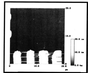
Figure 6 Atomic Force Microscope (AFM) observation after molecular combing. A single CNT is
clearly visible aligned with the direction of the pre-defined microelectrodes.
[31]4.2 Nanoconnection via HREBL
The approach for connecting a single CNT starts by mounting a sample in the AFM system
after the molecular combing. Inspection by tapping mode enables to confirm the presence of a few
number of CNT inside the region of interest close to the macro-electrodes (figure 6). A CNT is
chosen for nanoconnection according to the following requirement: longer than 3 mm, diameter
lower than 3 nm (as estimated by the height profile of an AFM scan through the CNT) and
elongated shape with no strong buckling. The location of this CNT with respect to the end of the
microelectrodes is determined using the AFM metrology software. Different sources of errors
cumulate (alignment inaccuracy in HREBL, registration inaccuracy) and can be detrimental for
successfully achieving the point contacts. However, as the selected CNT is long, straight and
correctly aligned, it is quite easy to adjust the length of the electrodes for compensating possible
inaccuracy. This may be viewed as a dull work, but it should be kept in mind that the density of
CNTs on the substrate is tunable [29]. Moreover, as the direction of the CNTs is known, it is much
easier to spot a CNT compared to an arbitrary deposition.
i0.0 - 20.0 rm 10.0 1U.U II I -~ I rll , ~ ---~I , zu. I
Figure 7 Scanning Electron Microscope (SEM) observation of a sample after nanoconnection (a).
AFM observation of the same sample (b). [32]
A typical result of successful single CNT nanoconnection is presented on Fig. 7. The 200 nm
wide nano-electrodes perpendicular to the 7 mm long CNT can be clearly seen. In this case, six
nano-electrodes are perfectly connecting the CNT. Fig. 7a illustrates the connection between the
microelectrodes and the nano-electrodes. The yield of this technique of nanoconnection turns out to
be 100% [29] as soon as a correct CNT, corresponding to the above mentioned requirements is
observed by AFM. As the molecular combing procedure is also very efficient (close to 100%), the
whole procedure is very reliable.
4.3 Alignment by Nanopelleting
The previous technique, although guided the growth of CNT, it is unable to make large-scale
and direct assembly of them. The nanopelleting concept overcomes this limitation by embedding
carbon nanotubes in micro-scale pellets that can be transplanted readily. This technique includes
vertical growth of carbon nanotubes, pellet casting, planarization, pellet separation, and
transplantation. A specific manufacturing process is developed and tested with favorable results.
This technology will enable directed assembly of carbon nanotubes in a long-range order [27].
Conceptually, a nanopellet consists of a CNT (or CNTs) embedded within a micro-scale
block. The block serves as a micro-scale transport vehicle, or carrier, for the nanostructure,
facilitating the handling and assembly of CNTs. Further, the embedded CNT (or CNTs) can also be
trimmed within the pellet via a chemical mechanical polishing (CMP) process (figure 8). Moreover,
nanopellets provide a seeding mechanism where CNTs can be grown and subsequently harvested; this enhances control over yield, enabling the fabrication of devices with large areas of high-quality CNTs [27]. Therefore, nanopelleting provides a functional periodicity to individual CNT (or CNTs), uncoupled from spatial and temporal process fluctuations normally experienced in CNT growth.
Figure 8 Trimmed CNTs via CMP process: (a) A side view of planarized CNTs. (b) An oblique view of the planarized CNTs. [33]
Applications that are particularly well suited to nanopelleting are those that require large expanses of arrayed CNTs with specific geometries, alignment, and location. Examples of such applications include field emission displays, where even a relatively small display of several square inches would require vast numbers of ordered CNTs. Other potential applications that may be enabled by this technique but are yet underexplored include the use of CNT arrays for nanolithography using photo/thermal/electron energy beams, as well as structural applications, such as carbon nanocomposites interconnects. Furthermore, given the broader utility of the nanopelleting concept in terms of multi-scale manufacturing, nanopelleting can be used more broadly for a variety of nanostructures and their applications.
4.4 Densification from Vapor Infiltration
Growth of aligned carbon nanotubes (ACNTs) is imperative for obtaining scaled-up functional nanotube devices for use as field emitters in nano-electronics, as sensors, and for several other applications including thermal management. However, due to the low density and high porosity of ACNT films, the as-grown ACNT films are too weak and easy to break. The high porosity also causes the ACNT films to have low effective electrical and thermal conductance, since
the interstitial space between nanotubes is only occupied by air. Densifying ACNT films by filling the interstitial space between nanotubes with solid materials could modify the properties of the ACNT films and provide them useful for applications that require increased robustness or hardness, protection from oxidation at high temperatures and other damaging environments, or increased effective electrical and thermal conductance. Chemical vapor infiltration [34] (CVI) is an alternate method that essentially extends the commonly-used CVD process to the filling of networks of pores within a fibrous pre-form by altering the deposition kinetics toward a mass-transfer limited process.
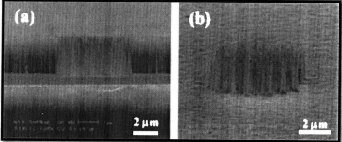
Figure 9 SEM photographs of ACNTs. P35
A simple method to produce densified and strengthened ACNT films (figure 10) exists by
combining the growth of ACNT films (CVD process) and the infiltration of pyrolyzed carbon (CVI process) in one step. Compression tests showed that the densified ACNT films were significantly
strengthened by three orders of magnitude. These property enhanced ACNT films can have several
potential applications, making up for the low density, and weakness and low effective conductivity of other pre-assembly techniques.
4.5 Densification for Interconnects
CNTs are a promising candidate for interconnect application mainly because of its abilities to carry a very high current density, to exhibit a ballistic transport along the tube, and to resist against electromigration. CNT bundles can potentially have higher conductivity than copper if
CNTs are closely-packed [36]. High site density (i.e., tubes per unit growth area) is critical for CNT interconnects because the denser the CNTs are, the more conduction channels there are, the less resistance is expected. However, the growth of closely-packed CNT bundles has not been realized yet, if not impossible.
Figure 10 CNT bundles (a) before and (b) after densification. P73
The reported CNT site densities are still one or two orders of magnitude less than the ideal ones. Sparse growth is even essential for the carbon source to reach the catalyst/CNT interface [38]. Therefore, it was proposed to densify the CNT bundles (figure 9) after growth as an alternative solution. It has been reported that after immersing into a liquid and drying, vertically-aligned CNTs aggregate into "mushroom" structures or cellular patterns due to capillary coalescence [39].
Densification in pre-assembly methods, combined with reliable CNT growth techniques, enables the realization of CNT interconnects with better performance than most conducting metals. Although densification processes are very efficient in achieving interactions between tubes and optimization of electrical properties, they do not address the existent challenge in scaling properties of a single nanotube into larger and practical CNTs arrays.
5 Proposed Assembly Methods
"Top-down" and "bottom-up " are two distinct approaches for assembling nano-scale materials and devices. Top-down approaches produces nano-scale devices by using externally controlled tools, fundamentally the micro-fabrication methods developed for the semiconductor
industry [40]. Such methods have pushed device features far into the nano-scale regime, and innovation in this field continues to overcome obstacles that appear initially to defy the continuation of Moore's law. However, at these diminishing length scales the costs of production spiral with decreasing size and fundamental physical limitations are reached.
Bottom-up approaches propose a new path in device design based on self-assembly. Self-assembly is in principle more compatible with the coherent design of materials at the nano-scale. It is also potentially less expensive, efficient and more environmentally friendly. Bottom-up relies on the concepts of molecular self-assembly or molecular recognition, in order to arrange nano-scale objects into some useful structure in order to build a device without guidance or management from an outside source [40]. It is unquestionably the case that the interface of the two approaches will provide with innovative and exciting discoveries for future years.
Existing nano-technology has profoundly emphasized the growth and synthesis of CNTs, while few assembly methods to integrate nanotubes into practical structures are accessible at the present time. As seen in the previous sections, there exist synthesis methods that allow for high-quality CNTs; however, there are no consistent methods for the assembly of applicable nanotube structures.
5.1 Interfacial Adhesion and Void Bridging
High modulus and high elastic strain qualify nanotubes as potential reinforcements in composite materials. Nano-scale continuous cracks in solids act as stress concentrators, but the failure of one fiber in a composite of loose coupled nanotubes would result in a slight overloading of adjacent tubes; therefore, crack growth would be suppressed. Loads are effectively transferred to the nanotubes, resulting in a composite modulus that is similar to that of an isotropic short fiber composite containing fibers of exceptional modulus and tensile strength. The high surface area of nanotubes creates a large interfacial region that can have different properties from the bulk matrix. Although interfaces have always been important in composites, the interfacial regions of nanotube composites are so numerous that they dominate the behavior of the bulk material.
Proof of increased interaction between matrix and fiber is manifest in the fracture surface micrographs, which shows nanotubes dispersed in a thermosetting polymer. Dispersion of nanotubes on the microscopic scale is apparent, and some load is transferred between the matrix
and reinforcement [4]. One proposed method for increasing this load transfer is to attach molecules to the ends or sides of nanotubes for better bonding. Functionalization at the molecular level brings a new level of design possibilities to composite materials, beyond common methods for increasing interfacial adhesion. It is unknown at this time how the addition of certain functional groups affects the mechanical strength of the tubes. However, the known extraordinary mechanical properties of nanotubes make development of high strength composites a worthy goal, although its achievement will be very difficult.
Direct testing of simple carbon nanotube-polymer composites has been used to quantify and isolate the interfacial adhesion between individual CNTs and polymer matrices [41]. The CNTs were found to bridge voids in the film so that most of the length of the nanotubes was bridging and a relatively small quantity of the length embedded within the epoxy film. An AFM was used to laterally deflect an individual nanotube until the embedded length was dragged out of the polymer film. The largest recorded interfacial adhesion strengths in these experiments were an order of magnitude greater than the typical engineering composite values, indicating excellent polymer adhesion to the nanotubes, although the large variability in the interfacial strength (35-376 MPa) suggests the occurrence of potentially different failure events.
Figure 11 An individual carbon nanotube is attached to the end of an AFM probe and embedded within a solid epoxy polymer. Separation of the probe from the polymer causes pull-out of the nanotube (right) with the force recorded from the bending of the AFM cantilever. [42]
Individual CNTs were attached to the end of an AFM tip and pushed the nanotube into a liquid copolymer, followed by solidification of the polymer, to produce single CNT composites. The
nanotube was then pulled from the polymer matrix and the critical force required for interfacial failure was recorded by the AFM (figure 12). All results showed a consistently high interfacial adhesion [43] between the nanotube and the polymers used. In addition, fracture mechanics approaches have also shown that significant energy is required to denature the nanotube from a polymer. The effect of inducing strong chemical bonding has also been investigated by modification of the carbon nanotube surfaces prior to individual carbon nanotube pull-out experiments. The relationship between the fiber diameter and the critical length importantly indicates how smaller diameters can improve the efficiency of polymer reinforcement. This relationship determines how the critical fiber length of approximately 1400 nm was significantly reduced to approximately 400 nm due to the chemical modification. It is important to note that the stresses developed in the polymer next to the nanotube during these tests are calculated to be far in excess of failure stresses of the bulk polymer material. Preferential crystallization of a higher modulus polymer inter-phase region at the nanotube surface during composite processing has been proposed as a possible explanation for the durability of this interface during composite loading [44]. Nonetheless, no matter how well assembled a polymer reinforcement is, CNT composites will never be as strong as individual CNTs unless the volume fraction of nanotubes approaches unity.
5.2
Yarning by Spinning
Nanotube spinning is motivated in part by interest in the very high strength and electrical and thermal conductivities of individual nanotubes. Breakthroughs have been made in wet spinning of SWNTs and in dry-state spinning of MWNTs and SWNTs [45], but the highest strength achieved with any of these spinning methods is about an order of magnitude lower than the strength of individual SWNTs, 37 GPa. There is no single best solution to the challenge of converting available nanotube powders into useful fibers and yams. Excellent fiber strength (4.2 GPa) and modulus (167 GPa) have been achieved by incorporating SWNTs in a high-strength, high modulus polymer, but electrical and thermal conductivities are low because of limitations on nanotube content [46]. Much higher conductivities result for thermally annealed, solution-spun yarns containing only SWNTs, but achieved mechanical properties are far lower than can be obtained using a polymer matrix for interfacial stress transfer. The goal is to produce yarns that are at the same time strong, creep resistant, highly conducting, and reversibly deformable over relatively large strains to absorb energy.
Figure 12 SEM images, at two different magnifications, of a carbon nanotube yarn in the process of being simultaneously drawn and twisted during pinning from a nanotube forest outside the SEM. [47]
Unlike singles yarn of a conventional textile, the MWNT singles yarn largely retains twist when the yarn ends are released. The enhanced locking of twist possibly reflects the high interfacial contact area per yarn volume as a result of the very high surface-to-volume ratio of the MWNTs (figure 14). Particularly surprising is the observation that twist is retained up to the location of the break point for singles yarns that have been broken by tensile extension.
Dissimilar from interfacial adhesion in CNT reinforced composites, nanotube yarns do provide with the desired solely CNT structure. Even thought tests have shown much higher strengths for yarns than for composites, the yarns are not as robust as individual CNTs. A better ordered structure is needed in yarns in order to allow bigger load transfers. An alternative method would be to assemble arrays of CNTs at previous fabrication stages.
5.3 Overlapping Configurations
The interactions of individual CNTs can play a decisive role in application and during fabrication processes and may pose significant challenges compared with macroscopic classical engineering applications. This is because at the nano-scale, weak dispersive van der Waals interactions play a more prominent role and often govern the mechanics or self-assembly dynamics
of those materials. The interplay of such adhesive forces with covalent bonding within CNTs is not well understood for many CNT systems.
Recent progress in the overlapped assembly of SWNTs (horizontally aligned and vertically aligned) from solution deposition and direct chemical vapor deposition and on possible growth mechanisms have come to light the recent years. Overlapped assembly of SWNTs constitutes a crucial prerequisite for high-throughput fabrication of carbon nanotube-based devices and integration with existing silicon technology and other biological hybrid systems.
MA*
Adhs Substrate
(a) Sputter oating and plasma treatment IIIIll IIIIIIll I
Figure 13 Schematic illustration of the procedures for fabricating multi-component, interposed CNT micro-patterns by dry contact transfer followed by region-specific adsorption. [48J
A simple unconventional method is proposed; a very effective and versatile dry contact transfer technique for the controlled preparation of 3D perpendicularly aligned CNT micro-patterns [49]. As shown in Fig. 11, this work starts with adhering a TEM grid onto Scotch tape as a mask, followed by sputter coating with silver through this mask (figure 9a). Then, the silver-patterned Scotch tape is subjected to heptylamine plasma treatment. After removal of the TEM grid (figure 9b), the Scotch tape is pressed on the as-synthesized perpendicularly aligned CNT film on a quartz plate. Subsequently, the Scotch tape is peeled off from the quartz substrate (Figure 9c, d) and the
II__·~ _
P7____7
nanotubes underneath the silver-free regions are therefore selectively transferred onto the Scotch tape as a positive image of the TEM grid whereas those covered by the silver-patterned areas remain on the quartz substrate as a negative pattern. By use of the strong interaction of NH2 groups with COOH groups, the authors further realized the self-assembly of nonaligned carboxylated CNTs into the discrete areas, that is, plasma polymer (heptylamine)-patterned areas, in the patterned structure of aligned CNTs (Figure 9e) [50]. This is the first report on the fabrication of multi-component, interposed aligned CNT micro-patterns.
Recently, it was reported the first use of long-range capillary forces to construct 3D micro-patterns on aligned CNT films through a water-spreading method after the synthesis of the nanotubes [51]. Understanding their results through a simplified model, it was concluded that low density regions or vacancies on the CNT films may play an important role in the formation of patterns. Following this conjecture, they have artificially etched regular vacancies on CNT films with a pulsed laser and have obtained various highly ordered aligned patterns. Roughly at the same time, it was reported a similar capillarity driven assembly method, in which the control of final structure, shape, and orientation was implemented by using patterned CNT films [39].
Capillarity driven assembly methods are very convenient since they act in an automated fashion as long as an appropriate fabrication process has been designed. Capillary forces propagate a chain of interactions between neighbor nanotubes, thus enabling self-assembly of CNT patterned arrays. A proposed method is to grow nanotube "forests" along an angle oriented substrate, this would allow for optimal nanotube grouping. Due to the complexity of successfully growing CNTs on a tilted surface, a simplified step configuration (figure 14) of the substrate will be considered. The grouping is achieved by tipping the CNT "forests" down the slope of the steps.
Figure 14 Schematic illustration of CNT "forests" (meshed surface) grown along the steps of a substrate.
i;
i
Based on the same principle, many other overlapping configurations could be designed. Moreover, pre-assembly (densification) and assembly (yarning) techniques can be merged to obtain even more interesting ways of achieving practical CNT structures. Hence, an unconventional assembly method would consist of densifying step-grown CNTs by vapor infiltration, then tipping down the "forests" along the slope, and finally spinning the resulting string. The string will be the results of the capillary forces interactions between the tipped CNTs down the steps of the substrate. Repeating the same steps for the interposed CNT micro-pattern case shown in Fig. 13 could yield in higher strengths due to improved fiber lengths (slope-tipping) and higher energy densities due to higher nanotube volumes (densification).
Various methods based on the self-assembly of CNTs on chemically modified surfaces to prepare parallel aligned and patterned CNTs have received great attention recently because of the associated mild process conditions and the ability to produce well-defined CNT structures. There are endless permutations of these newly discovered techniques that will eventually lead the way to the next era of manufacturing processes.
6 Future Considerations
Realization of the ample potential of CNTs in their developed and prospective applications requires the controlled and predictable assembly of well-ordered structures. The theoretical and practical questions posed by this stipulation have captivated the dedication of many researchers, who have endured extensive progress along two key paths, assembly as-synthesized and post-synthetic assembly. The field is now hastily developing, and it is probable that major innovative results will be reported as the years pass. The development and application of a series of new methods has led to enormous advances in the assembly of CNTs. The methods range from the manipulation of individual nanotubes or their bundles on the nanometer-to-micrometer length scale for nano-scale applications, to much larger-scale methods for organizing large quantities of nanotubes over large
(centimeter-scale) areas.
Assembly methods are now available for the patterning of CNTs on a variety of substrates, including plastics, and in two and three dimensions. Promising applications include integrated devices, nano-porous biomaterials, and nano-structured textiles. It is feasible that the soon available reliable methods will enable actual application of CNTs. A variety of limitations do still remain. An
ongoing setback is that the carbon-based materials produced by CNT synthesis methods contain both semiconducting and metallic nanotubes. Recent reports addressing the separation and purification of semiconducting and metallic CNTs are certainly a breakthrough, but still higher yield and purity is desired. Applications which may be closest to practical use, such as biomaterials and nano-structured textiles, are hindered by the continuing high market price of CNTs. Further developments in growth techniques and further development of assembly methods will be needed for the realization of the desired technology of nanotube-based devices and materials engineering.
7 References
[1] R. Signorelli (MIT), Nanotubefilaments on battey's electrode (2006) [online] [2] A. Kis, A. Zettl, Phil Trans. R. Soc. A 366 (2008), p.1 5 9 2
[3] A. Kis, A. Zettl, Phil Trans. R. Soc. A 366 (2008), p.15 9 1- 1 6 1 1 [4] B. Files and B. Mayeaux, Advanced Materials & Processes (2000), p.1-2 [5] S. Kim, Superbydrophobic Carbon Nanotube Carpet (2008), p.3
[6] S. Kim, Superhydrophobic Carbon Nanotube Carpet (2008), p.3
[7] M.Scwartz, New Materials, Processes, and Methods Technology (2005), p.4 0 1 [8] W. Kraitschmer et aL, Nature 347 (1990), p.3 5 4
[9] Y. Ando, S. Iijima, Jpn. J. AppL Phys. 32 (1993), p.L107 [10] S. Iijima, Nature 354 (1991), p.56
[11] Y.Ando et al, Materials Today 7(9) (2004), p.2 2-2 9
[12] Y.Ando et al., Materials Today 7(9) (2004), p.
23[13] X. Zhao et al, Chem. Phys. Lett. 373 (2003), p.2 6 6 [14] H. Huang et al, Chem. Phys. Lett. 343 (2001), p.7 [15] A. Thess et al, Science 273 (1996), p.4 8 3
[16] T. Guo et al, Science 257 (1992), p.1 6 6 1 [17] Y.Ando et al, Materials Today 7(9) (2004), p.2 5 [18] M. Kanai et al, Appl Phys. Lett. 79 (2001), p.2 9 6 7 [19] R. Sen et al, Chem. Phys. Lett. 332 (2000), p.4 6 7 [20] T. Yoshitake et al, Physica B 323 (2002), p.1 2 4 [21] Y.Ando et al, Materials Today 7(9) (2004), p.2 7 [22] G. Tibbetts, J. Cryst. Growth 66 (1984), p.6 3 2
[23] N. Nagaraju et al., J. Mol. Catal. A 181 (2002), p.5 7 [24] E. Couteau et al, Chem. Phys. Lett. 378 (2003), p.9 [25] J. Hafner et al, Nature 398 (1999), p.7 6 1
[26] J. Hafner et al.,J. Am. Chem. Soc. 121 (1999), p.9 7 5 0 [27] T. EI-Aquizy et al., Appl. Phys. Lett. 85 (2004) p.5995 [28] F. Carcenac et al, Eng. 61-62 (2002) p.657-663
[29] M. Sagnes et al., Microelectronic Engineering 67-68 (2003) p.683-689 [30] S. Gerdes et al, Europhys. Lett. 48 (3) (1999) p.2 9 2-2 9 8
[31] M. Sagnes et al., Microelectronic Engineering 67-68 (2003) p.6 8 6 [32] M. Sagnes et al., Microelectronic Engineering 67-68 (2003) p.6 8 7 [33] T. El-Aquizy et al., Appl. Phys. Left. 85 (2004) p.5996
[34] Q. Gong et al., Solid State Commun 131 (2004), p.399-404 [35] Q. Gong et al, Solid State Commun 131 (2004), p.4 0 0 [36] A. Naeemi et al, IITC (2006), p.2 2 1-2 2 3
[37] Z. Liu et al., IEEE 1-4244-1070 (2007), p.2 0 2
[38] D. Futaba etal.,
J.
Phys. Chem. B, 110 (2006), p.8 0 3 5-8 0 3 8 [39] N. Chakrapani et al., PNAS, 101 (2004), p.4 0 0 9-4 0 1 2[40] L. Huang et al, J. Mater, Chem., 17 (2007), p.3 8 6 3-3 8 7 4 [41] C. Cooper et al., Appl. Phys. Lett. 81 (2002), p. 3873 [42] W. Wang et al, Phil. Trans. R. Soc. A 366 (2008), p.1618 [43] A. Barber et al., Appl Phys. Lett. 82 (2003), p.4140-4142 [44] K. Ryan et al., Compos. Sci. Technol. 67 (2007), p.1640-1649 [45] Y. Li et al., Science 304 (2004), p.2 7 6
[46] R. Baughman et al, Science 297 (2002), p.7 8 7 [47] M. Zhang et al., Science 306 (2004), p.1 3 5 9
[48] J. Yang et al,

![Table 1 The properties of single-walled carbon nanotube. [5]](https://thumb-eu.123doks.com/thumbv2/123doknet/14201022.479950/10.918.131.718.702.999/table-properties-single-walled-carbon-nanotube.webp)