BULBOUS BOW DESIGN OPTIMIZATION FOR FAST SHIPS
by
GEORGIOS KYRIAZIS
B.S. Marine Engineering Hellenic Naval Academy, 1988
Submitted to the Department of Ocean Engineering in partial fulfillment of the requirements for the degrees of
Naval Engineer and
Master of Science in Ocean Systems Management at the
MASSACHUSETTS INSTITUTE OF TECHNOLOGY June 1996
© Massachusetts Institute of Technology 1996. All rights reserved
A uthor Author... ...-.. . - - ,......
Department of Ocean Engineering May 10, 1996 C ertified by ... ..." ... .:. ...: ...
Paul D. Sclavounos, Professor of Naval Architecture Thesi-Supervior, )epartment of Ocean Engineering
C ertified by ...
Alan J. Brown, Wofessor of Naval Construction and Engineering Thesis Reader, Department of Ocean Engineering
A ccepted by ... ... ...
Douglas A. Carmichael, P~ofessor of Power Engineering oFiT CrA.urjN) o, •o, Chairman, Ocean Engineering Departmental Graduate Committee
JUL 2
6
1996
,n
LIBRARIESBULBOUS BOW DESIGN OPTIMIZATION FOR FAST SHIPS
by
GEORGIOS KYRIAZIS
Submitted to the department of Ocean Engineering on May 10, 1996 in partial fulfillment of the requirements for the Degrees of Naval Engineer and Master of Science in Ocean
Systems Management.
ABSTRACT
Using the TGC-770, a fine-form, high-speed vessel, as the reference hull form, a series of variant hull forms with bulbous bows was designed. These variants were analyzed hydrodynamically utilizing the code SWAN, in order to investigate the effects of changes in bulb parameters on the total calm water resistance and seakeeping performance of the original TGC-770 original hull form. The wave resistance coefficients calculated by SWAN were combined with model test results to estimate the total calm water resistance for all hull forms. In addition, heave and pitch RAO's as well as the added resistance in head seas were calculated by the code so that the effect of the bulb could be determined.
Finally, a total logistics cost savings comparison of the original and the bulbous bow hull forms and its effect on latent and stimulated demand revealed the advantages of the bulbous bow hull form for fine-form, high-speed ships.
Thesis Supervisor: Paul D. Sclavounos
ACKNOWLEDGMENTS
I would like to express my sincere thanks to Professor Paul D. Sclavounos for his guidance and our discussions all along this last year. I would also like to thank Professor Alan J. Brown for his advice and comments.
I also wish to associate David Kring for all his understanding cooperation in the use of the code SWAN and Alexis Mantzaris for his help with the code TUBOLA.
Finally, this work is dedicated to my parents. Without their encouragement and support everything would have been much more difficult.
Table of Contents
1 Introduction 2 Literature review
2.1 General ...
2.2 Theoretical approach ...
2.2.1 The ship's-bulb's waves... 2.2.2 Optimum bulb sizes for an elementary sine ship ...
2.2.3 Superposition of elementary bulbous sine ships ... 2.3 Existing design methods ...
2.3 The behavior of ships with bulbous bows in waves ...
2.5 Applications of bulbous bows on ships ...
2.5.1 Applications on big tankers and bulk carriers ...
2.5.2 Applications 2.5.3 Applications 3 Geometry of bulbs 3.1 Hullform ... 3.2 Bulb selection .... 4 Computer programs 4.1 Introduction ... 4.2 Autoship ... on fishing boats ...
on high speed ships
. ... 10 .... 16 ... .. .. . 17 ... 20 ... 22 ... 26 ... 30 ... .. 3 1 ... 3 1 ... 33 ... 34 36 ... 36 ... 37 55 ... 55
4.3 SWAN (Ship Wave Analysis) ...
4.3.1 General description ... .... ... ... 4.3.2 Input files ... 4.3.3 Output files ... 58 58 59 60
5 Resistance and seakeeping results 62
5.1 Introduction ... 62
5.2 Calm water resistance results ... ... 66
5.2.1 Residuary resistance ... 66
5.2.2 Frictional resistance ... ... 66
5.2.3 Total calm water resistance ... 69
5.3 Unsteady flow results ... 72
5.3.1 Heave and pitchRAO's ... 73
5.3.2 Added resistance ... 83
6 Market review and benefits 86 6.1 Introduction ... ... ... ... 86
6.2 Total logistics cost analysis ... 88
6.2.1 FastShip value creation model ... 88
6.2.2 MIT total logistics cost model ... 91
6.2.3 Supply chain management ... 95
6.3 Latent and stimulated demand ... 97
6.4 Competitive responses ... ... 101
7 The bulbous bow as an investment 104 7.1 Assumptions... ... . ... ... 104
7.2 Life cycle savings by selecting a bulbous bow ... 106
7.3 Total logistics cost analysis ... 110
7.3.1 Bulbous bow effect on transportation cost ... 110
7.3.2 Total logistics cost model results ... 112
7.3.3 Sensitivity analysis results ... ... 113
7.3.4 Latent and stimulated demand ... 115
8 Conclusions 116
Bibliography 119
List of Figures
2-1 Bulbous bow types ... 15
2-2 Reduction in bow wave resistance due to an optimum point doublet ... 23
2-3 Optimum spherical bulb for sine ships ... 23
2-4 Entrance angles of elementary ships ... ... ... 23
2-5 Experimental set-up for the wave survey method ... 29
3-1 Bulb's geometry ... ... 38
3-2 TGC-770 hull geometry ... ... 41
3-3 Variant # 1 hull geometry . ... ... 42
3-4 Variant #2 hull geometry... .... 43
3-5 Variant # 3 hull geometry ... .... ... 44
3-6 Variant #4 hull geometry ... 45
3-7 Variant # 5 hull geometry ... 46
3-8 Variant # 6 hull geometry ... 47
3-9 Variant # 7 hull geometry ... 48
3-10 Variant # 8 hull geometry... ... 49
3-11 Variant # 9 hull geometry ... ... 50
3-12 Variant # 10 hull geometry ... 51
3-13 Variant # 11 hull geometry ... ... 52
3-14 Variant# 12 hull geometry ... 53
3-15 Variant#13 hull geometry ... .. 54
5-1 SWAN's computational grid for TGC-770 ... 64
5-2 Steady wave pattern for TGC-770 at 40 knots ... 65
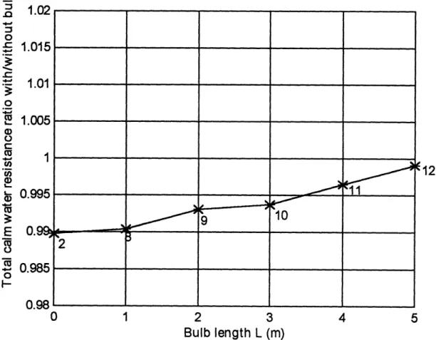
5-3 Bulb's length effect on total resistance ratio with\without bulb ... 70
5-5 Heave motion RAO (variant # 1 compared with TGC-770)
5-6 Pitch motion RAO (variant #1 compared with TGC-770) ... 76
5-7 Heave motion RAO (variant #2 compared with TGC-770) ... 77
5-8 Pitch motion RAO (variant #2 compared with TGC-770) ... 77
5-9 Heave motion RAO (variant #3 compared with TGC-770) ... 78
5-10 Pitch motion RAO (variant #3 compared with TGC-770) ... 78
5-11 Heave motion RAO (variant #4 compared with TGC-770) ... 79
5-12 Pitch motion RAO (variant #4 compared with TGC-770) ... 79
5-13 Heave motion RAO (variant #5 compared with TGC-770) ... 80
5-14 Pitch motion RAO (variant #5 compared with TGC-770) ... 80
5-15 Heave motion RAO (variant #6 compared with TGC-770) ... 81
5-16 Pitch motion RAO (variant #6 compared with TGC-770) ... 81
5-17 Heave motion RAO (variant #7 compared with TGC-770) ... 82
5-18 Pitch motion RAO (variant #7 compared with TGC-770) ... 82
5-19 Pierson-Moskowitz wave spectrum ... ... .. 84
5-20 Added Resistance RAO (variant #7 compared with TGC-770) ... 84
6-1 Total market size and FastShip's loadings ... ... 87
7-1 Contributing factors to total logistics cost ... 111
List of Tables
3-1 TGC-770 main dimensions and form coefficients ... 373-2 Variants bulb parameters ... 40
5-1 Form factors for hemispheric bulbs at U= 40 knots ... 68
5-2 Total calm water resistance calculations ... ... 69
5-3 Mean added resistance calculations ... ... 85
7-1 Present value total savings calculations ... 107
7-2 Net Present Values for seven different investments ... ... 109
7-3 Freight rates for variants ... 110
Chapter 1
Introduction
Today, the possibility of numerical potential flow calculations by use of codes directly allows naval architects to investigate hull changes before tank testing. Although tank testing is still required at the final stage, since the potential flow calculations do not accurately predict the actual flow fields and viscous effects, the latter are sufficiently accurate, in a relative sense, to optimize the hull form before model testing begins. This approach to hull design optimization was successfully used in recent years by several scientists.
An area in which small changes in underwater hull form geometry can lead to significant changes in ship total resistance is in the use of bow bulbs. Chapter 2 presents a
literature overview for this area of study. Although naval architects have realized since the turn of the century that the addition of a bulb to the bow can reduce the total resistance of the ship, most research has concentrated primarily on low speed, full form ships.
The objective of this study was to investigate the effects of changes in bulb parameters on the resistance and seakeeping performance for a high speed, fine form ship (TGC-770). The bulbous bow design methodology, which was used to design and fair the bulb into the rest of the hull, and the bulbous bow variants that were investigated are presented in Chapter 3. Chapter 4 presents the computer codes that were used in this study to design the bulbous bow hull variants and predict their resistance and seakeeping performance.
Chapter 5 presents the results from the numerical potential flow calculations for the bulbous bow variants. The effects of the bulb's length and diameter on total calm water resistance, added resistance, heave and pitch RAO's in head seas were studied.
This high speed vessel is designed to operate in the North Atlantic serving the transatlantic trade. Chapter 6 presents the North Atlantic freight market and the benefits that TGC-770 is going to provide to shippers in terms of total logistics cost savings. In Chapter 7 an operating cost savings analysis for the bulbous bow variants and a total logistics cost comparison with TGC-770 are performed.
Finally, Chapter 8 gives the conclusions drawn from this study for the potential use of a bulbous bow in the final hull design of TGC-770.
Chapter 2
Literature review
2.1 General
Nearly 90 years ago, R. E. Froude interpreted the lower resistance of a torpedo boat, after fitting of a torpedo tube, as the wave reduction effect of the thickening of the bow due to the torpedo tube. D. W. Taylor was the first to recognize the bulbous bow as an elementary device to reduce the wavemaking resistance. In 1907 he fitted the battleship Delaware with a bulbous bow to increase the speed at constant power. In spite of great activities in the experimental field to explore its potential, seventy years passed before the
bulb finally asserted itself as an elementary device in practical shipbuilding. Especially for fast ships, the use of a bulb allows a departure from previously accepted design principles for the benefit of a better underwater form.
The most important effect of a bulbous bow is its influence on the different resistance components and consequently on the required power. For a better understanding,
the following subdivision of the total resistance (R, ) is used :
RT= Rv + RWF +±Rw = RF + RV + R + R",
where
R, = viscous resistance
R, = frictional resistance
RVm = viscous residual resistance R, = wavemaking resistance R, = wave-breaking resistance
The latter two components are related to wavemaking. Their contributions to the total resistance are very different for ships with different block coefficients and speeds.
The additional bulb surface always increases the frictional resistance R,, which is the main part of the viscous component Rv. Up to now, it is not quite clear whether the bulb affects the viscous residual resistance RV due to the variation of the velocity field in the near bow range.
There is no doubt concerning the influence of the bulbous bow on wavemaking resistance R, . The linearized theory of wave resistance has rendered the most important contribution to the clarification of this problem. According to this theory, the bulb problem is a pure interference problem of the free wave systems of the ship and the bulb. Depending on phase difference and amplitudes, a total mutual cancellation of both interfering wave systems may occur. The longitudinal position of the bulb causes the phase difference, while its volume is related to the amplitude. The wave resistance is evaluated by analysis of the free wave patterns measured in model experiments.
The wave-breaking resistance R, depends directly on the rising and development of free as well as local waves in the vicinity of forebody and is a question of typical spray phenomenon. Understanding the breaking phenomenon of ship waves is important in the bulb design for full ships. The wave-breaking resistance includes all parts of the energy loss by the breaking of too-steep bow waves. The main part of this energy can be detected by wake measurements. The local wave system contributes the main part to this resistance component. This wave system consists primarily of the two back waves of bow and stern which are generated by deflection of the momentum.
The wave-breaking resistance can be diminished only insofar as it is possible to prevent the breaking of bow waves. According to the reason of its creation, this is only possible by changing the deflection of momentum or the bow near the velocity field, respectively. In general this can be achieved not only by a bulbous bow, but by suitable hydrofoils as well.
It has been shown by model experiments and by linear theory that the effect of a bulb cannot be achieved by variations of the hull form, such as an increase of the block coefficient corresponding to the bulb volume or an elongation of the ship length corresponding to the bulb length.
The exact effect of bulbous bows on the prementioned components of resistance depends on the form of the ship, on the speed and on the loading condition. Therefore it is important to realize that a specific ship-bulb combination that shows a good performance at a certain condition may behave poorly at an off-design one.
As far as the seakeeping effects of the bulbous bow are concerned, no attempt to solve theoretically the problem has been found in the literature. The current practice is to proceed with the design in view of the calm water performance only and to investigate the seakeeping aspects by doing model tests.
From the above, it can be concluded that the question shouldn't be which is the optimal bulb for a specific ship, but rather which is a good one in terms of combining favorable characteristics in all the operational conditions of the vessel.
In addition to reducing the resistance of a hull form, bulbous bows also influence other properties of a ship. Model tests have shown that bulbous bows can influence the quasi-propulsive coefficient, wake fraction and thrust deduction fraction. However, it is not certain if these bulb effects are present in the full scale ship because of the importance of scale effects on the expansion of these model test results. Bulbous bows do not seem to significantly influence course stability or maneuverability, although the bulb behaves as a 'rudder' in the bow. Model tests in regular waves tend to indicate that the bulbous ship is the best ship,in terms of resistance, regardless of seakeeping aspects up to a wavelength to ship's length ratio of about 0.8.
Moreover, slamming and resultant hull damage are also a concern, though in general there is little evidence that ships with bulbs have suffered any worse in this respect. Out-size bulbs introduce some problems in berthing and anchoring. As these factors present no reasons sufficient to prevent the utilization of a bulbous bow, it appears that bulb design may be based solely on calm water characteristics.
For ice navigation, ships equipped with bulbous bows have a definite advantage. The bulbs tend to tip the ice floes so that they slide along the ship's hull on their wet side, which has a smaller friction coefficient. Therefore, the speed loss of a ship equipped with a bulbous bow in ice is less than that of the same ship without a bow bulb.
Furthermore, the bulb is an ideal place for the arrangement of bow thrusters and acoustic sounding gear. Many warships today carry large sonar equipment forward and
certainly every effort should be made to house these in bulbs which will at least not add to the hull resistance at service speeds.
Recognizing the importance of the bulb form in reducing a ship's resistance, it is necessary to classify bulbs according to some geometric parameters. Kracht [1] differentiated bulbs into three main categories according to the shape of the bulb's cross section at the forward perpendicular. These three classes are presented below and are depicted graphically in Figure 2-1.
V
-
TYPE
SD-
TYPE
A-
TYPE
Figure 2-1 : Bulbous bow types
SV - Type : Figure 2-1 shows the nabla type of bulb which has a drop-shaped sectional area. However, its center of area is situated in the upper half, indicating a volume
concentration near the free surface. Because of its favorable seakeeping properties, this type is the most common bulb in use today.
* O - Type : This type, also shown in Figure 2-1, has an oval sectional area, a center of
area in the middle and a central volumetric concentration. All the circular, elliptical and lens-shaped bulbs as well as the cylindrical bulbs belong to this type.
* A - Type : Figure 2-1 shows the drop-shaped sectional area of the delta type bulb with the center of area in the lower half. This shape indicates a concentration of the bulb volume near the base. The Taylor bulb and the pear-shaped bulbs belong to this type.
2.2
Theoretical Approach
In this section, the problem that the bulbous bow attempts to solve is described. Furthermore, the methods and guidelines currently used in its design are described. The theoretical approach presented is that by Yim [2].
2.2.1 The Ship's
-
Bulb's Waves
In the following analysis, the right handed rectangular coordinate system O-xyz is defined so that the origin is located on both the undisturbed free surface and the bow stem : the x-axis, in the direction of the flow at infinity, the z-axis positive upward. According to Inui [3] , the regular wave system in the negative -x direction created by a doublet at (0,0,- z, ) with strength -u is given by the following formula :
5b = -p Ab(0)sin{k sec2 (xcos+ y sin9)} dO
0
(2-1)
where
'b is the bow wave amplitude
0 is the angle between the ship's course and a line perpendicular to the crest of a divergent wave
Ab (0) is the amplitude function :
Ab( ) = 8k2 exp(-kz, sec2 0) sec4 0
Any ship can be approximated by a centerplane source distribution : (2-2)
BN
m= (-1)" 2 n=O
(2rx)2n
(2n)! (2-3)
on D = {y=0, O<x<l, O>z, >-T)
where T is the draft to length ratio and B is the beam to length ratio.
This distribution produces regular waves as a superposition of positive elementary sine waves :
f,
= A,(0) sin(k sec2()(xcosO+ ysin0))d8 (2-4)
where A, is the ship wave amplitude function :
A,s()
=
(1
-
e
- ~T•ee))
-2n-k ,
(ksec9)2n(2-5)
We see that A, is proportional to B and therefore a proper combination of B and p will minimize the superposed amplitude function.
Yim assumed the ship to be the superposition of n elementary sine ships, each one represented by the source distribution of equation (2-3) :
f = ~x,z) I +pz) ] a, sin( w D-X )
where x = x, and x = 1- x, are the end points of each of the elementary sine ships and the constant
f
is the longitudinal average of the vertical slope of the ship surface near the water surface.Equation (2-6) describes the surface of a ship which is symmetrical fore and aft. However, this symmetry is not important in the problem discussed here. The coefficients a, and 8 have to be obtained so that the forward part of a given ship is closely represented by equation (2-6).
Surface waves may be considered to be linearly superposable. Therefore, if each elementary ship creates minimum amplitude waves, the total waves resulting from the superposition of waves created by each elementary ship will likely be of minimum amplitude. In general, the distances between bow waves of elementary sine ships are much smaller than the ship wave length for operational speeds. Thus, interactions between bow waves of elementary sine ships are almost always unfavorable and decrease with the amplitudes of the waves due to each elementary sine ship. Consequently, each elementary sine ship can be made into an optimal bulbous sine ship by finding a doublet at the bow which minimizes the wave resistance.
2.2.2 Optimum bulb sizes for an elementary sine ship
Haverlock gives the following wave resistance formula:
R =
(A12+
A22) cos0
3 dO 0(2-7)
where A1 and A2 are amplitude functions of the sine and cosine elementary wave
systems, respectively.
If only the bow wave resistance is considered, we can write:
RIB
2{-pAb(9)+Aa(0)})2
cos30
dO0
(2-8)
where
R,B is the bow wave resistance due to the combination of a doublet at
(0,0,-z, ) with strength -p and an elementary sine ship-source distribution represented by equation (2-6). Also:
A 4BEk2sec4
0 =4BEksec2 Z 7r z 2n
(k2
sec
2-
2) =(ko
sec9)
2Ab (0) = 8k2 exp(-kz, sec2 9) sec4 0
We can minimize R,, by setting:
Op B
-- A()Ab()COss
3Od
Bof
A
b () 2 cos30
dO 0 (2-9)For a deeply submerged sphere of radius rb in an otherwise uniform flow, there is a relation:
3
S=rb
(2-10)
which means that p is proportional to the bulb volume. Since for a sine ship with the entrance angle aE
tan(aE B=
2 2
the optimum bulb volume is proportional to tan( a ) a- , or half the angle of
2 2
entrance.
In linear theory, from the concept of wave cancellation there is no doubt that as far as the sine ship is concerned, the best longitudinal position of a sphere which minimizes the wave resistance in inviscid flow is at the bow stem. It is also known that there exists a
doublet distribution which totally cancels bow waves if the doublet is distributed on an infinitely long vertical line at the bow stem. According to Yim, the optimal doublet distribution on the vertical bow stem from the free surface to the keel is a bugle shape having the maximum strength at the keel and creating an onion shape bulb. In general, as it can be seen from Figure 2-2, the best shape of the vertical doublet distribution along the bow stem is almost equivalent to the concentration of the doublet near the keel. In practice, the vertical location of the bulb is generally selected in order to make the flow to the keel smooth by locating the center of the bulb at one bulb radius above the keel. Figure 2-3 presents the relation between the vertical location and the optimal sizes of bulbs for a sine ship with L/T = 20 and for different half angles of entrance. Reference [2] includes more diagrams for different L/T ratios.
2.2.3 Superposition of elementary bulbous sine ships
The first thing to be considered in the superposition of the elementary bulbous sine ships is the allocation of a bulbous section on the sectional area curve of a given ship. Although each elementary sine ship has a slightly different Froude number and it is better to calculate the optimum bulb size as accurately as possible, it can be assumed for convenience that the Froude numbers are the same for all the elementary ships considered here.
0.15 020 0.25 0.30 0.35 0.40 OAS
FROUDE NUMBER, VI/v
Figure 2-2 : Reduction in bow wave resistance
due to an optimum point doublet located at various depths at the
stem of sine ship
FROUDE NUMBER V/yj9
I 7 r
0.8 1.0 12 1A 1.6
V•,i L/,- 20
Figure 2-3 : Optimum spherical bulb for sine ships
Figure 2-4 : Entrance angles of elementary ships
- --- I -- -
--Consequently, the T/L ratios are not very different and bulb sizes are not very sensitive to T/L . Then, there exists an interesting, simple relationship between the slope of the waterline and the total bulb volume. In Figure 2-4, a load waterline ABCG of a ship, which is hollow near the bow and has one inflection point, is considered to be divided into elementary sine curves, starting from points A, B and C respectively. It can be assumed that the tangent at each point almost coincides with the curve. Therefore, the entrance angle of the sine ship at B is almost equal to the angle b between two tangents from A and B. Similarly, angle c is almost equal to the entrance angle of the elementary sine ship at C. It is easily seen in Figure 2-4 that :
1
2aE +b=d 1
-a,E+b+c=e
2
Since the bulb volume is proportional to the entrance angle of the elementary sine ship for a given Froude number, we see that the total bulb volume is the same as that for the optimum bulb for the sine ship of entrance angle e or, approximately, the same as the optimal bulb size at E for waterline ECG. The bulb volume has been considered to be smoothly distributed along the curve ABC corresponding to the entrance angles of the elementary sine ships at as many points as possible. However, in practice it is not necessary to take too many points, but rather to spread the bulb volume obtained at each point to form a smooth total section area curve. Thus, except for the bulb at the forward perpendicular of the original ship, the additional sectional area due to the optimum bulb at a station can be represented by the optimum bulb volume divided by the proper segment
length between the adjacent stations where the bow stems of the elementary ships are located. It is recommended to consider the bulb volume :
4nr rb3 V
4
;r
bb(2-11)3 BHL BHL
spread over the given interval 1, / L [= (x,,, - x,_~) / 2] centered at x, . Thus, the
approximate sectional area of the bulb at x, is sb / (BH) = Vb / (BHI,).
In order to avoid flow separation, the bulb volume at the forward perpendicular (FP) should be split in half, one half to be distributed immediately aft of FP and the other half forward. Careful attention should be paid into making the flow around the bow to the bilge smooth, while keeping the total volume of the bulb optimum.
The shape of the bulb in front of the forward perpendicular of the original ship would be almost spherical if only inviscid flow was considered. However, in practice, the bulb volume assigned forward of the FP may be formed as a horizontally oriented circular cylinder with a spherical or parabolic nose smoothly fitted to the bow. If the original ship is like the sine ships without the hollow part of the waterline near the bow, any other bulb volume used to fair the bulb to prevent flow separation would contribute to increased wave resistance. Here, a tradeoff with separation is necessary. If a change of the original ship form is permitted, a redistribution of bulb volume may be considered with the corresponding waterline change without changing the total volume of the bulb.
2.3 Existing Design Methods
In 1960, Takahei [5] developed a method of designing what he called a 'wave-making resistanceless hull form'. After having verified experimentally that the wave'wave-making characteristics of a bulb can be practically represented by an isolated point doublet, he used stereo-photography to analyze the wave pattern and to confirm the condition of wave cancellation.
The main hull was represented as a source distribution which creates a pure positive sine wave, whose origin is always at the bow, no matter how the Froude number changes. Furthermore, the hull didn't have a parallel middle body in order not to create shoulder waves.
The bulb wave can for all practical purposes be replaced by a point doublet wave. This wave has inverse phase (negative sine) with respect to the bow (and stem) waves. Thus, it is possible to select a bulb of spherical shape whose volume corresponds to the selected doublet. The relationship between the strength M of the doublet and the radius r of the sphere is given by the following formula :
M = 27c r 3V
Takahei's study deals only with the cancellation of bow waves. However, stern waves can be treated in a similar manner [5] .
In 1965, Van Lammeren and Wahab [8] investigated the effect of large spherical bulbs in the resistance of a fast cargo liner. The radius of the sphere needed to reduce the bow wave system as much as possible was determined by a simple approximation theory, using the same method adopted by Havelock [6], [7] and Inui [5]. The resulting equation was:
(, r a F= e W ( a- er/F ) (2-12)
2rr (1- r2 F4)
where
r is the radius of the sphere
L is the length between perpendiculars
F is the Froude number (= V/lF)
a is the double angle of entrance
f is the distance of the center of the sphere from the waterline
Van Lammeren's experiments investigated the optimum location of the sphere relative to the bow, the effect of the angle of entrance on wave resistance and, finally, the reduction in total resistance. This reduction was found to be 8.9% at Fn = 0.27.
In 1966, Couch and Moss [9] published their findings from a model test program whose purpose was to investigate the effect of different bulbs installed on tankers. Three series of bulbs were designed, each as an attempt to investigate changes in certain
parameters. The reduction achieved in effective horsepower was as much as 25% in ballast and as much as 10% in full load condition, both at design speeds.
Kracht [1] presented a comprehensive design method for bulbous bows in 1978. His paper describes a quantitative design method for bulbous bows, together with the necessary data providing relationships between performance and main parameters of ships and bulbs. The data, presented in the form of design charts, are derived from a statistical analysis of routine test results of the Hamburg HSVA and Berlin VWS Model Basins, respectively. Three main hull parameters are taken into account : block coefficient, length/beam ratio and beam/draft ratio, while six bulb quantities are selected and reduced to bulb parameters, of which the volume, the section area at FP and the protruding length of the bulb are the most important. For power calculation, the total power is subdivided into a frictional and a residual part. Depending on bulb parameters and Froude number, six graphs of residual power reduction for each block coefficient have been prepared .
Another bulb design method is the XY wave survey method. According to this method, the energy flux out of a control volume ABCD is measured (see Figure 2-5). This results in the wave resistance :
R,
= pg (I+0.5AB A2)where I= XYdx , A is the amplitude of the following waves at the point of
XB
trancation of the wave signals and X, Y are the x, y components of the force exerted by the model wave system on a long thin vertically oriented circular cylinder at a distance y
= AB from the model centerline. The term 0.5 AB A2 measures the energy flux through
AB.
tAM UM
Figure 2-5 : Experimental set-up for the wave survey method
The hull form used in the wave survey was the MARAD 'Securtity Class' multi-purpose mobilization ship and it was found that an elliptical bulb is the most appropriate to minimize the bare hull resistance at design speed, under a combination of ballast and full loads.
2.4 The behavior of ships with bulbous bows in
waves
Much of the research into the effects of bulbs has been devoted to resistance and powering aspects. The effects on sea-going qualities must also be investigated before the decision is taken to apply a bulb for any particular case.
The first effort to determine the performance in waves of a ship fitted with a bulbous bow was made by Dillon and Lewis [10]. Four systematically-related passenger ship models having bulbous bows ranging from 0 to 13.5% of the midship area were tested both in calm water and waves. The tests showed a substantial reduction in resistance in calm water above Fn = 0.245 and a small effect of bulb size on speed and motions in head seas. Therefore, it was concluded that the design of the bulbous bows can be performed on the basis of calm water considerations alone.
In 1965, Wahab [8] conducted tests on a model of a 500 feet cargo liner in regular and irregular head seas. The model was tested both without a bulb as well as with a spherical bulb with a radius of 2% of the ship's length. It was concluded that reduction in pitch and in relative motions of the bow are obtained with the bulb up to a wave length which depends on the ship's speed. Nevertheless, it was also shown that the advantage of the bulb vanishes in bad weather (i.e. at sea state 8 and above).
Van Lammeren and Pangalila [11] tested the model of a 24,000 DWT bulk carrier in irregular seas with a conventional bow and with a 9% bulb attached in the bow. Negligible differences in pitch motions and in bending moments were found after measurements for both cases. However, in the ballast condition and for sea state 6 the model with the bulbous bow still required less power to attain speeds above 13 knots. Moreover, the bulb reduced the relative motions of the bow.
In 1970, Smith and Salvesen [12] investigated the accuracy of the Korvin-Kroukovski strip theory for destroyer hull forms with bulbous bows. They concluded that, with sufficiently accurate section representation, the strip theory can be used to predict head-seas motions not only for regular hull forms, but also for ships with bulbous bows and
sonar devices in small amplitude waves.
2.5 Applications of bulbous bows on ships
2.5.1 Applications on big tankers and bulk carriers
Large bulbs are now commonly fitted to big tankers and bulk carriers running at low Fn values, at which the wavemaking resistance is relatively small. Reductions in resistance
of approximately 5% in full load and 15% in the ballast condition have been obtained in model tests. These results are also confirmed in full scale trials. Such gains are apparently possible on ships with block coefficients around 0.80 and at Fn values of about 0.18 . It is significant that the most substantial improvements are found in the ballast condition when the bulb is near the free surface.
Newport News Shipbuilding performed studies [13] to determine the economic and hydrodynamic effects of alternative bow configurations on a representative modern, high-block tanker. A computational fluid dynamics software (SLAW) was used in order to mathematically analyze several candidate bows. These designs were then model tested to validate the results of the code. The powering results obtained from the model testing confirmed that the initial predictions made using the code were correct. For the same cruising speed of 15.5 knots a cylindrical bulb attached to the bow resulted in a reduction to total resistance of approximately 3.5%, while the second best result (a 2% reduction of total resistance) was achieved by a 'producible' bulb candidate. The latter kind of bulb was a long, thin bulb, which had a simpler form than the cylindrical one in order to reduce the complexity and construction costs.
In 1994 an existing tanker hull form and slight modifications of this were extensively tested at MARIN [14]. The modifications comprised a lengthening of the parallel midbody, a shortening of the bulbous bow length and a movement of the rudder location aft, while further one additional bow thruster opening (three instead of two), a
bottom cargo system opening and one additional stern thruster opening (two instead of one) were fitted on the existing ship model.
This design problem was efficiently solved by using mathematical tools. A potential flow calculation carried out with MARIN's DAWSON code helped the design team to make the modifications of the hull form in such a way that the contractual speed could be predicted. The results of the subsequent model tests were in line with the high expectations based on the potential flow calculations and the contractual speed was achieved.
The major conclusion drawn is that without this CFD code these design problems would not have been solved so easily and so quickly.
2.5.2 Applications on fishing boats
Trawlers run at high values of Fn (0.30 to 0.37) and have large wavemaking resistance. These are conditions which should be favorable to the use of bulbous bows and this have been confirmed by model experiments. In the U.S. several bulbous bow installations have been included in the conversion of West Coast crabbers to trawlers.
Doust [15] conducted tests with the models of two long distance trawlers, differing only in that one of them had a bulbous bow. Two propellers were tested with each form, one suitable for free-running and the other for trawling. Doust concluded that overall reductions in power of the order of 10-15 % can be obtained, due to reduction in
resistance and increased propeller efficiency. Furthermore, tests performed in regular waves indicated that the bulbous bow ship suffered a smaller speed reduction over the working speed range than the conventional bow ship did.
Heliotis [16] studied the effect of bow bulbs on trawler forms similar to the ones used in New England. The conclusion from this study was that the introduction of a cylindrical bulbous bow can reduce the total resistance of trawlers up to 20%. Furthermore, from the seakeeping tests the bulbous bow showed an advantageous effect in reducing the pitching motion and the vertical bow acceleration at cruising speed and for wavelengths up to
X/L
= 2.2.5.3 Applications on high speed ships
To date, the only full-scale applications of large bulbous bows to high-speed vessels are those found on naval ships (such as the Italian frigate Maestrale).
A problem that has arisen in high-speed ships with bulbs is the occurrence of cavitation on the bulb surface, resulting in erosion and noise. Calculations should be made in order to ensure that the curvature is nowhere sharp enough to cause cavitation. Special attention should be paid to smoothing off weld beads and other roughnesses in this area.
A methodology for designing bulbous bows for high-speed, fine-form ships was proposed in 1984 by J.W. Hoyle, B.H. Cheng and others [17]. This study was performed
using the FFG-7 class of naval frigates as the reference hull form. Nine variations in bulb design plus the bulbless hull form were analyzed using numerical tools. The hydrodynamic performance of the candidate bulbs was predicted by two computer programs. First, the XYZ Free Surface Program was used to assess the calm water resistance characteristics of the FFG-7 configured with and without bulb forms. Then, the Navy Standard Ship Motions Program (SMP) was used to predict their seakeeping performance.
Five of the bulb variations were appended to a model of the FFG-7 and tested in the towing tank at the U.S. Naval Academy. The most interesting conclusion from this study was that the results from the computer predictions and the calm water towing tank tests showed remarkably similar trends, while the relative rankings of the bulb forms were identical. In general, the resistance advantages from adding a bulbous bow to the FFG-7 hull form seemed to increase with increasing bulb volume. Furthermore, the addition of a bulbous bow to the FFG-7 hull form appeared to only marginally degrade the ship's
seakeeping characteristics. Although the O-type bulb form has not been investigated extensively (from the nine different designs only one very small bulb was of this type), the authors of this paper note the superior performance of this type of bulb. They also recommend the future study of the effect of variations on the O-type bulb form.
Chapter 3
Geometry of bulbs
3.1 Hull form
The original hull form of TGC-770 was modified in order to create several hull variations with bulbous bow .The modifications consisted of applying different bow bulbs to the basic form. The main dimensions and form coefficients of TGC-770 are given in the following table :
Table 3-1 : TGC-770 main dimensions and form coefficients
3.2 Bulb selection
It was decided that the bulbs to be tested would be circular cylinders with a hemispheric nose. This form was chosen because it is the simplest one and the easiest to be
Length on WL (m) 229.0 Breadth max. on WL (m) 35.37 Maximum Draught (m) 10.00 Displacement (m'3) 29,080 Wetted surface (m') 8,878 Block coefficient 0.3713 VCG (m) 17.0 Rx about CG (m) 14.0 Ry about CG (m) 67.2 Rz about CG (m) 67.2
implemented by a shipyard. Furthermore, most bulbs incorporated in original ship designs are of that form.
I
Figure 3-1 : Bulb's geometry
As it is shown in Figure 3-1, a circular cylinder of length L and diameter D attaches the hemispheric nose of diameter D to the bow of the ship. In order to fair the bulb into the rest of the hull a computer program (Autoship) was used. A short description of the methodology applied to fair the bulbs is given in the following chapter.
The following parameters had to be specified for each bulb to be tested :
1. Vertical location
Two conditions had to be specified for the vertical location of the bulbs. First, the bulbs had to be fully submerged and second they should not extend beneath the baseline, so that no additional precautions will have to be taken during the dry-docking. For the largest bulbs, there was practically only one position that satisfied both conditions. The smaller diameter bulbs, that were tested, were located as deeply as possible. In all cases, they were kept parallel to the water line.
2. Bulb diameter
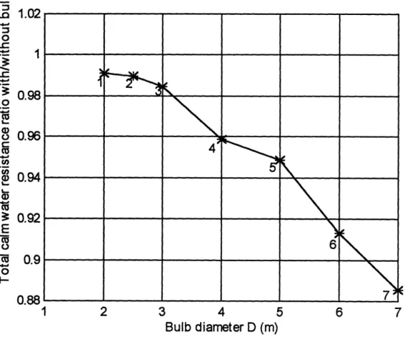
Since all the existing design methods presented in the previous chapter have concentrated primarily on low speed, full form ships, it was decided to test seven different diameters of bulbs in order to cover all the realistically possible range of sizes and investigate the effect of bulb's diameter in resistance and seakeeping.
3. Bulb length
For one of the smallest bulbs (diameter 2.5 meters) six variants of different bulb length were tested and for the largest bulb (diameter 7.0 meters) two variants with different bulb length were also tested.
Applying the above guidelines thirteen TGC-770 bulb variations were produced and were named variant #1 - #13 (variant #0 was named the original TGC-770 hull). The bulb
diameter (D) and length (L) for each variant are given in the following table :
Table 3-2 : Variants bulb parameters
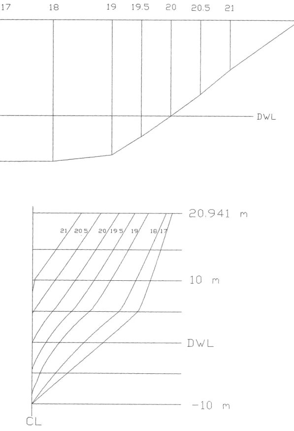
Figure 3-2 presents the original hull geometry of TGC-770 and figures 3-3 - 3-15 the thirteen variants' hull geometry.
VARIANT # D (m) L (m) 1 2.0 0 2 2.5 0 3 3.0 0 4 4.0 0 5 5.0 0 6 6.0 0 7 7.0 0 8 2.5 1.0 9 2.5 2.0 10 2.5 3.0 11 2.5 4.0 12 2.5 5.0 13 7.0 10.0
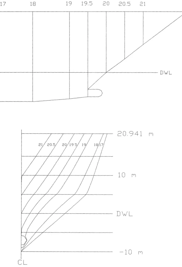
19 19,5 20 20.5 21 DW!L 21 205C 20 195L 1 18
CL
20,941 rn
10
m
D0
-10
MFigure 3-2 : TGC-770 hull geometry
~I~ _
111_1_____1 -~ Il~i
f
,·/
19 19,5 20 20.5 21
20,941
m
21 205 20 19.5 19 181Oz
CL
10
-10
m
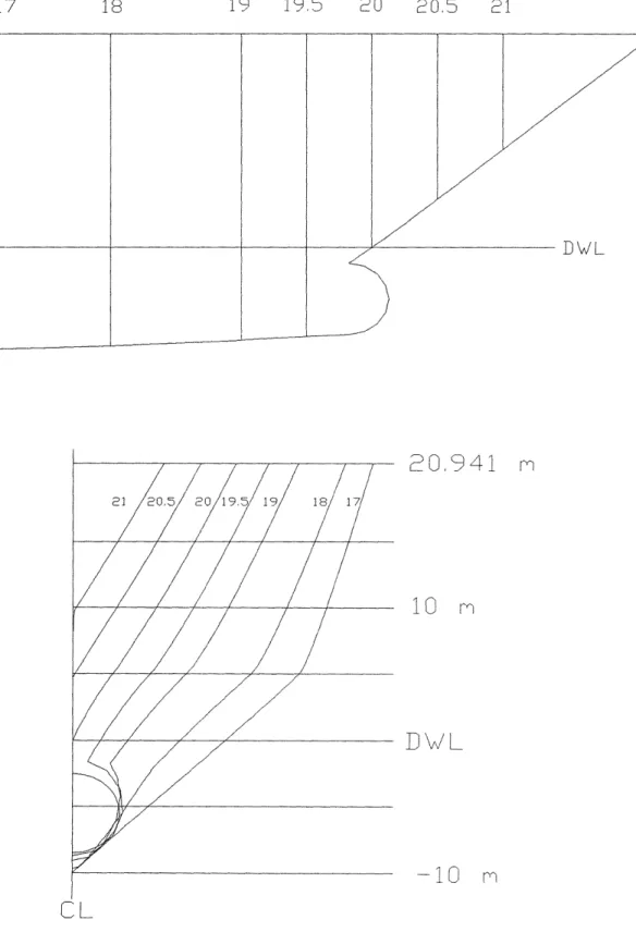
Figure 3-3 : Variant #1 hull geometry STN 17 18
STN 17 18 19 21 205 20 195 19 1817 CLL
20,941
m
-10
M
-10 M
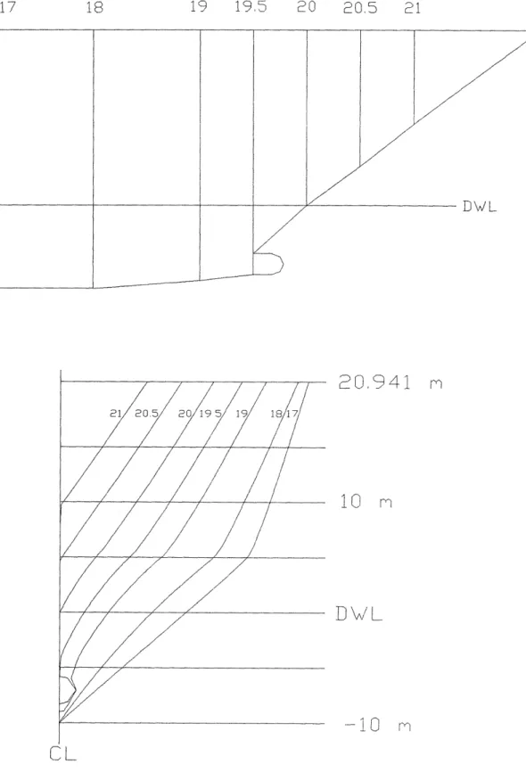
Figure 3-4 : Variant #2 hull geometrySTN 17 18 19 DWL 2 1205 80 19.5/19 1817
20.941 m
10 m
D
/L-10
m
Cl
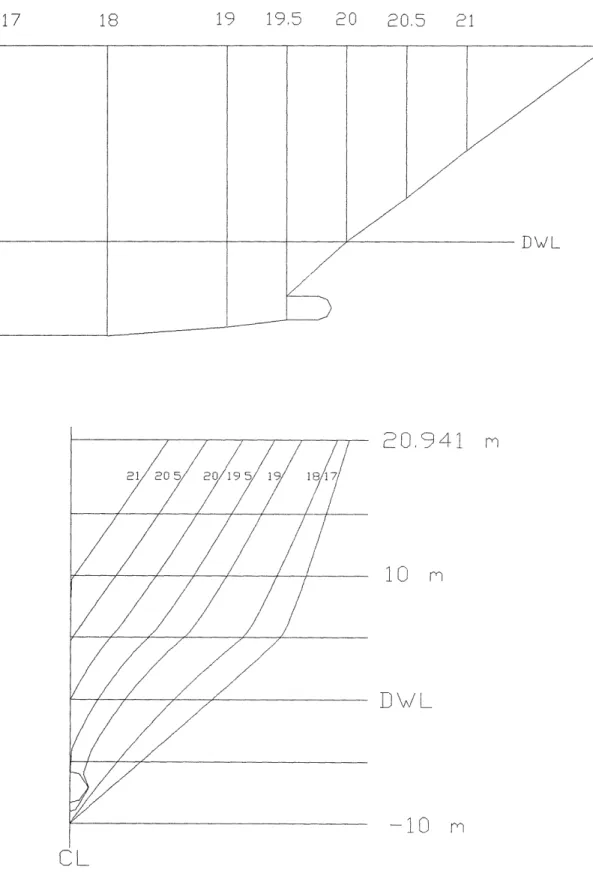
Figure 3-5 : Variant #3 hull geometry
19.5 20 20.5 21
zz
YZZ
ZZ
--- -//i
v19 19.5 20 20.5 21 21 20/,5 20 195 19 1817
CL
20.941 m
DL0
m
-10
iFigure 3-6 : Variant # 4 hull geometry
STN 17 18 19 19,5 20 20,5 21
1
20CL50195
19
1817
CL
20.941
m
DWL
-10
iSTN 17 18 19 19.5
21C20L 2019 19 18 1
CL
0,941 m
-10
m
Figure 3-8 : Variant # 6 hull geometry
Th\
D/WL
20 20,5 21
19 19.5 20 20,5 21
20.941 m
10
m
D-10 m
-10
m
Figure 3-9 : Variant # 7 hull geometry
DWL
STN 17
zz
ZZ/
STN 17 18 19 19,5 20 20.5 21 SWL 21 205 20 CL19519 1817 CL
20.941
m
10 M
DV/
-1
M
--±0 L~Figure 3-10 : Variant # 8 hull geometry
---
---ZZ
•WL /z
lJSTN 17 18 19 19 5 20
21 20,5 20 195 19
117
CL20.941 m
10
m
-_0 m
Figure 3-11 : Variant # 9 hull geometry
Th\ It
D UW L
20,5 21
LJWL
19 19,5 20 0.,5 21 /i
20.941
10
DWL
-10
CL
Figure 3-12 : Variant # 10 hull geometry
DWL ~ _1_1 ______ _ z ~ I~ STN 17
ZZ
STN 17 18 19 21205 20 195/ 9 18 1
7 / /
20,941 4
10 m
D\/L-10
rn
CL
Figure 3-13 : Variant # 11 hull geometry
ZZ I D UW L
77777
1771 / //
/
77
19,5 20 20,5 21 LJWZ
~//YX
STN 17 18 19
211 0.5 20 195 19 1917
C L
20,941
m
-10
m
Figure 3-14 : Variant # 12 hull geometry
STN 17 18 19 19.5 20 DWL
20.941
m
21 20.5 2 0 19.5 19 18 1 I ir~ IU i'I-10
m
CL
Figure 3-15 : Variant # 13 hull geometry
___I~ --- II---Y_____ ~~
'---14V/
20,5 21z
I
/·'Chapter 4
Computer programs
4.1 Introduction
Two computer programs were utilized :
* Autoship was used to design and fair the bulbs into the rest of the hull and finally produce the offsets of each variant's underwater hull form.
*
SWAN-1 (Ship Wave Analysis) was run to predict the calm water resistance characteristics and also the seakeeping performance of the TGC-770 configured with and without bulb forms.An overview of the operation of these two programs is presented here. A more detailed description of the computer programs and their operation is given in references [18] and [19].
4.2 Autoship
Perhaps the most important disadvantage of all bulbous bow design methodologies is that they fail to provide a means for fairing the bulb into the rest of the hull. The integration of the bulb into the ship's hull is left entirely to the designer's discretion. One useful computer tool that has been utilized in this study in order to design the bulbous bows of the thirteen variants is Autoship.
By introducing the original hull form of TGC-770 to Autoship, it was relatively easy
to design the thirteen bulbous bow variants and fair the bulbs into the rest of the hull. In order to design each variant the following procedure was followed :
* First, the original hull form was modified in the bow stem depending on each bulb's parameters (diameter D, length L and vertical location).
* Then, each variant was tested for fairness. The 'Surface Normal Curvature' feature of Autoship is a test for fairness. Just a single curve, to be fair, has to have continuous distribution of curvature, whereas fairness of a ship hull requires a continuous distribution of normal curvature along each longitudinal. Checking the normal curvature along a series of longitudinals is a test of fairness that is far more sensitive than looking
at the lines by eye, especially with the limitations of raster graphics.
* In addition, each variant was tested for 'buildability' of the hull, assuming the vessel is to be plated with metal. This is performed by Autoship's feature 'Gaussian Curvature'. Zero Gaussian curvature means that a surface is either flat or curves only in one
direction. Areas of low Gaussian curvature, which are developable, display in different color on the screen than areas of high Gaussian curvature do. The latter areas are highly curved and require considerable distortion of sheet material in order to conform to the desired hull shape.
* Finally, the faired hull offsets for each variant were produced by Autoship.
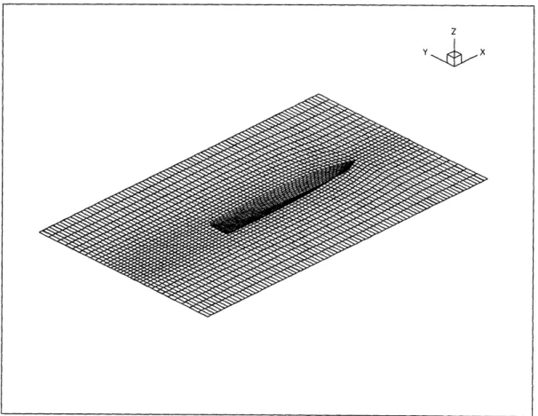
Having the hull offsets for each variant from Autoship a computer code in Fortran was used to generate a surface grid of each hull and bulb (Appendix 1). The hull, when appended with a bulb, was subdivided into two sections. The first section consisted of the underwater hull up to the depth where the upper part of the bulb starts. The rest of the hull, which includes the bulb, formed the second section. This separation of the underwater hull renders moderate the production of underwater hull forms with bulbs of different length (L) by just modifying the second section of the hull.
4.3 SWAN (Ship Wave ANalysis)
4.3.1 General description
Computer based simulations of free surface flows past ships and sailing yachts have enjoyed rapid growth in use since the early 80's and in recent years have been firmly established as a versatile and inexpensive design tool at the disposal of the modem naval architect. SWAN is a computer program developed at MIT and has been used for the hydrodynamic analysis and design of several America's Cup entries. It solves the complete three-dimensional free surface flow around ships advancing with a constant forward velocity in calm water and in regular waves. SWAN models the generation, radiation and diffraction of surface waves by the ship hull by enforcing appropriate linearized free surface conditions with variable coefficients on the mean position of the free surface. This computer program is able to compute the localized flow properties inside the fluid domain, over the hull and on the free surface near and far from the ship.
The numerical solution algorithm is based on a Rankine panel method developed for the accurate treatment of forward speed free surface flows over a wide range of speeds and wave frequencies. Panels are distributed on the ship hull and part of the free surface and the appropriate boundary conditions are enforced by a bi-quadratic spline collocation scheme and the application of Green's second identity. A detailed numerical analysis of the
properties of this Rankine panel method was shown to introduce no numerical damping and a third order numerical dispersion to the wave disturbance. This property is essential not only for the accurate solution of the free surface flow around the ship but also for the reliable prediction of the far-field wave disturbance which may be advantageously employed in the evaluation of the ship wave resistance by momentum analysis.
The selection of the Rankine panel solution scheme in SWAN was motivated by several factors. It is based on the evaluation of Rankine influence coefficients which are independent of the speed and wave frequency using techniques which have been extensively developed and tested over a period of three decades. The distribution of panels on the free surface allows the enforcement of quasi-linear free surface conditions with variable coefficients. Finally, the use of the Rankine source as the Green function, combined with an iterative method for the solution of the resulting linear systems, leads to the efficient solution of both the calm water wave resistance and seakeeping problems.
4.3.2 Input files
The executable code field needs three input files : the HGD, AGD and FCP files. The executable response reads one additional input file (the RCP file) and a journal file created by field in order to calculate the resistance and seakeeping performance. A short description of the input files follows :
* The Field Control Parameter (FCP) file which contains input control parameters, such as the forward speeds of the ship and the incident wave headings and periods.
* The Hull Geometry Description (HGD) file which describes the hull geometry. The geometry of the hull surface is supplied to SWAN in the form of a mesh of points lying on it. The centerplane is assumed to be a plane of symmetry for the hull, therefore only half the hull surface need to be discretized.
* The Appendage Geometry Description (AGD) file which describes additional rigid surface that may be introduced as separate boundary sheets of the computational domain.
All such 'secondary' boundaries are referred to as appendages. The appendages
supported by the utilized version of SWAN (version 2.2) should be fully submerged. * The Response Control Parameter (RCP) file which contains all the user-supplied data
needed for the execution of response.
The HGD and AGD files, that were used as an input to SWAN for each variant, were an output of the Fortran code mentioned in the previous section.
4.3.3 Output files
The execution of field produces a single output file which serves as the interface between field and response. The user controls the number of output files by response. The
names of the response output files are supplied as control parameters by the RCP file. For this study two output files were required at each execution of response :
* The FMOUT file which contains all forces acting on the hull and the resulting responses of the vessel. A detailed label including the overall characteristics of the hull geometry as well as the size and density of the computational grid is printed in the beginning of the
file.
* The WPOUT file which contains the detailed flow solution over all boundaries of the computational domain. The wave elevation is printed over the free surface and the free
Chapter 5
Resistance and seakeeping results
5.1 Introduction
This chapter presents the hydrodynamic analysis carried out for the original TGC-770 hull form and the variants with bulbous bows, with the code SWAN. This vessel is intended for operation in the waters of North Atlantic, consequently its hydrodynamic performance was carried out in a typical severe North Atlantic sea state at the service speed of 40 knots.
The TGC-770 is a patented ship design developed to achieve and maintain a speed of 40 knots in severe North Atlantic sea states. The hydrodynamic analysis presented in this chapter was carried out for all the hulls cruising at a speed of 40 knots. For all computations in irregular seas the sea spectrum was selected to be a Pierson Moskowitz stationary sea spectrum with mean zero upcrossing period of T, = 10 seconds and
significant wave height H,,,3 = 6 meters. Only head waves (f8 = 1800) were considered.
The SWAN computations were conducted along the following general lines. A calibration of the computational method was first carried out for the supplied TGC-770 loading condition. A mesh of panels is set up over the hull and the free surface and following several iterative executions of the code numerical convergence is achieved for all quantities under study. This allows the removal of discretization error from the SWAN computations, an essential prerequisite for the runs reported in the following sections of this chapter.
A computation was first carried out for the steady flow around the vessel advancing
at 40 knots in order to determine the hull sinkage and trim. With the final sinkage and trim of each hull at calm water, wave making resistance computations were carried out for all thirteen variants with bulbous bows as well as for the original TGC-770 hull (steady flow computations). In addition, numerical computations were carried out for seven of the variants ( variants #1- #7) and the TGC-770 hull form for the heave and pitch motions and the added resistance in regular monochromatic waves over a broad range of frequency in head waves.
Figure 5-1 illustrates the hull and free surface discretization around the TGC-770 and in Figure 5-2 a convergent computation is shown of the steady wave pattern of the TGC-770 advancing at 40 knots.
Figure 5-1 : SWAN's computational grid for TGC-770 z
Y X
__
Z
x
5.2 Calm water resistance results
5.2.1 Residuary resistance
The SWAN-i code was primarily used to evaluate the resistance performance of the thirteen variants with bulbous bow and the original hull of TGC-770 cruising at the service speed of 40 knots (Fr = 0.434) . SWAN computed the wave resistance, based on the
integration of surface pressure on the hull and convergence tests were carried out to establish the insensitivity of the wave resistance to the number of panels used. These computations were done for each hull at the sinkage and trim calculated by the code.
After wave resistance predictions were made, the residuary resistance coefficients
(C, ) were obtained by adding an estimated induced drag coefficient to the wave resistance
coefficient (Cw) that SWAN calculated. The induced drag coefficient was estimated by relating the SWAN's result for the original TGC-770 hull to a corresponding model test result given in reference [26].
5.2.2 Frictional resistance
The frictional resistance coefficient for the hull of each variant was obtained from the following empirical expression known as ITTC 57 :
0.075
Cf = (5-1)
Co (logo Re-2.0)2
This frictional resistance coefficient represents the frictional resistance coefficient of
a flat plate. The ratio between the real frictional drag (Cf,rea, )and the flat plate frictional
drag ( Cfo) defines the form coefficient (k) :
1 + k - ,re"" (5-2)
Cfo
This difference between the real frictional drag and the flat plate frictional drag is partly due to the curvature of the hull. This curvature affects the pressure distribution along the length, causing the velocity to change. Using the code Tubola [27] which computes the evolution of a turbulent boundary layer over a two dimensional convex or concave section by using the Lag-Entrainement method of Green, Weeks and Brooman, the form coefficients for each bulb were calculated. The geometric modeling of each bulb was made by assuming a hemisphere attached to a semi-infinite cylinder. The rest of the hull for each of the thirteen variants as well as the total hull of the original TGC-770 were assumed to have a form factor kh = 0.12 ( a typical form factor for ships as mentioned in reference [24] ). The results from the runs of this code are shown in the following Table 5-1.
The form factors for hemispheric bulbs that were calculated by the code Tubola are negative. This is due to the fact that as the flow passes the hemispheric bulb's nose it meets a negative pressure gradient. Therefore, the boundary layer that is formed is smaller than that of a flat plate of the same surface and so the frictional resistance does.