1
Investigation Robot on Cables – 15250
D. Chadrin*, F. Degrutere*, G. Veidig*, J. Seyssaud**, N. Mahjoubi**, P. Devaux** *
DERICHEBOURGServices Industries ([email protected]) **
Commissariat à l’Energie Atomique et aux Energies Alternatives ([email protected])
ABSTRACT
The Decontamination and Decommissioning (D&D) Operations take place in hostile environments to the human intervention. In this context, robotic systems are a solution to achieve these operations while minimizing human intervention. Among these operations, the monitoring of lengthwise plant has to be performed in places where the radioactive contaminations make hostile environments. These monitoring operations need to measure several physics parameters in several locations in a precise and safe manner. These repetitive tasks can be made by robots that are simple, small sized and easily adaptable. In this scope, a robotic system on cables has been designed to control and monitor the inside of lengthwise nuclear facilities. In lengthwise installations, the using of cables allows to increase the covered zone of the robots which is an essential quality in such places. Unlike cable-driven parallel robots used in workspaces of 2D or 3D controlled by redundant tensioning motors, the current robot moves in a 1D workspace. Thus a tractors cable controlled by one tensioning motor is used to drive the robot on carrier cables. In this paper, we will describe the first results of this work by bringing out the innovation of our system. Then, we will discuss the perspective to upgrade the actual system whose applications could be perfectly imagined outside the nuclear D&D industry.
INTRODUCTION
The French Nuclear Safety Authority fixes a typical radiological upper limit for radiation workers exposure to 20 mSv per year [1]. When this limit is reached, a work should stop any activities inside of a nuclear installation. This limitation implies a need of important manpower and associated risks in order to deal with decommissioning dockyards and subsequently, an increase of the related costs. Considering this regulatory limit and the high dose rates in some nuclear installation, the use of robotic systems to assist or replace human operations seems to be a solution to conduct these operations in a safe manner [2].
Among these operations in particular, conducting monitoring and control campaigns inside of lengthwise installations [3]; thus, independent of the radiation protection constraint, justifying the use of robots, these occasional or periodic campaigns need a large amount of measurements. Further, in view of the large size of the facilities, robots will allow us to reduce the cost of these
2
monitoring campaigns, increase the accuracy of the measurements and ensure the robustness and repeatability of such operations. The most mobile robots typically use wheeled, tracked or legged to move on the ground. One of the drawbacks of this kind of mobile robots is their difficulty to access the entire site due to range limitations. Indeed, most the decommissioning sites are large in terms of size, most monitoring operations can encounter a difficulty, or to be caught on obstacles. Furthermore, the power supplies are also responsible of the range limitations of this kind of robots. Indeed, if the robots is tethered (where a power cord is trailed behind the robot), the cord has a limited length and may snag on obstacles. Likewise, if the robots carry a power source (such as a battery) with them, it is often heavy and has to be recharged regularly. With the aim of minimizing such drawbacks and increasing the efficiency of the robots operating in large facilities, we have to increase its range of mobility [4]. Thus, one solution is to use cables deployed in height inside the facility to monitor. The use of cables allows increasing the ability of the robots to operate in large areas while avoiding the interference with the other activities of the facility. The actuator of the robot is a motor placed outside the facility. This type of robot is linked to motor by traction cables to ensure its movement on carrier cables.
In this paper, we will present an illustration of these developments, highlighting the innovative aspects of this solution. Then, we will focus on discussing developments of this solution to meet future requirements inspections.
APPLICATION TO A TELEVISUAL INSPECTION SYSTEM
The original need behind these developments is the inspection of the concrete structure of a nuclear installation [5]. These inspections focus on the upper internal parts located at a height of 5 meters. On Figure 1, we can see a representation of this kind of installation on which we can note the lengthwise aspect of the facility. The chosen solution is a robot on cable that can browse the site on its greater length (between 40 and 65 meters). The periodical inspection must evaluate visually the concrete structure and detect the eventual surface defects. The monitoring of the detected failures will allow following their growth. A robot using cables to move inside this kind of facility has two advantages. First of all, this technology allows us to inspect the entire installation in expedited manner despite its large size. Secondly, it avoids the interference with obstacle elements arranged on the ground or with others mobile ground robots used for maintenance tasks.
3
Figure 1 – Representation of a storage site for radioactive waste
Our system of inspection is formed by two batches of equipment. The first one is installed permanently on the civil engineering structures prior to any inspection. It is used to introduce the inspection robot into the installation and to define its path inside it. The second batch is formed of equipment introduced temporarily inside the installation to monitor. Thus we will present our robot system by distinguishing the equipment according their properties permanent or temporary. Permanent Equipment
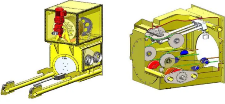
The permanent equipment articles are formed by a pair of intervention boxes (Figure 2) located on either side of the installation and of cables. The intervention boxes contain the mechanical devices that are used to strain the cables and govern the movement of the inspection robot. Given the expected nuclear application, the design of the intervention boxes must perform a containment function when the robot is manipulated for the introduction and extraction of the installation. The implementation of these intervention boxes requires performing coring within the walls of the facility that are then blocked by biological protections sized to allow the subsequent intervention of operators nearby in a safe manner.
Figure 2 - Intervention boxes
The other permanently installed equipments are the cables used to support and guide the inspection robot when an inspection is performed. These textile cables have a low linear density (4 to 5 times lower than the steel) and a high tensile strength modulus. These mechanical properties allow straining the cables to maintain a sufficient rigidity to reduce the deflection
4
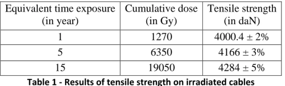
under the weight of the inspection robot. The structure of thesecables and its selected materials reflect its high quality in terms of good tensile strength (about 39.2 kilonewtons similar to a steel cable of equivalent diameter1). Furthermore, this property ensures an optimal operation of the inspection robot by securing its path inside the facility avoiding any contact with the structure. That is why the impact of ionizing radiation on the characteristic of tensile strength has been looked in detail particular by performing various radiation tests. In operation, these cables are tensioned to a tension of 2200 dekanewtons in a radiating environment. The results of these radiation tests are reported in Table 1.
Equivalent time exposure (in year) Cumulative dose (in Gy) Tensile strength (in daN) 1 1270 4000.4 ± 2% 5 6350 4166 ± 3% 15 19050 4284 ± 5%
Table 1 - Results of tensile strength on irradiated cables
In this scope, a set of cables have been irradiated with a cumulative dose equivalent to an exposition of 1, 5 and 15 years with respectively 1270, 6350 and 19050 Gy. Tensile testings have been performed on this set of cables until the break of specimens to evaluate the tensile strength at failure. The type of cables used is the one that the tensile strength after irradiation is consistent with that of non-irradiated cable (in accordance with the manufacturer’s data).
In addition, the structure of theses textile cables ensures both safety factors relating to the intervention in the nuclear industry (electrical and fire risk). Indeed textiles are insulators which forewarned of the risk of spread lightning. A special attention has been put to this aspect due to the fact that the intervention boxes are situated outside the installation. The flame propagation is also eliminated due to the particular structure of the cables that avoid the fire risk.
Temporary Equipment
In addition to these two devices installed prior to any investigation (intervention boxes and cables), this inspection system is composed of three devices used temporarily. It is an inspection robot, a storage box associated and a supervisory staff to communicate with the inspection robot. The role of the inspection robot is to carry the set of sensors in the area to inspect. It is placed on the supporting cables previously stretched in the installation. The so-called "tractors" and "carriers" cables are those mentioned above.
The design of the truck of the inspection robot is performed in a way that combines both stiffness and light weight of the structure. This structure houses all the relevant sensors to the mission
5
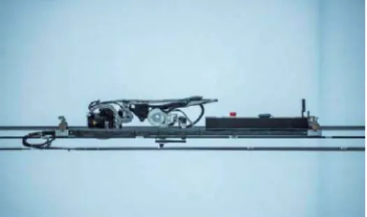
without that its own weight be a large percentage of the global weight supported by the cables. The truck is fixed on the cable by means of a fly-off to prevent the fall of the robot in case of failure of one of the two “carries” cables system. Figure 3 shows a configuration of the robot equipped with a digital camera.
Figure 3 - Inspection robot placed in the "carriers" cables
This inspection robot must be inserted and removed safely from the nuclear facility where the investigation should be made. For this purpose, a storage case with a metal frame and Plexiglas walls has been developed (Figure 4). Its design allows preserving the containment facility during docking or leaving the investigation robot ensuring tightness. It is equipped with round glove that allow maintenance on the robot and control the level of contamination of its structure.
Figure 4 - Storage case
Once the robot introduced in the facility, communication and data transfer between the robot and the checkpoint control robot is done via radio link. For this purpose, a radio antenna is positioned at the intervention box when the robot is introduced and removed during its extraction. However, in case of failure of the communication system, it is always possible to control the robot via the wired connection to bring it back to the intervention box.
On this basis, the perspectives for the actual system will be focused on the integration of additional equipment to meet the needs of specific radiological mapping.
6 FUTURE WORK
Following this first work that led to integrate the operational constraints, a study is underway to improve this inspection system on cables by the adding of additional sensors. This approach is conducted in the interest of standardization of this system especially by having a capacity of adaptability to the specific cases encountered and with a lower cost. However the notion of standardization is complex, given the diversity of cases that need to be addressed in terms of installation configuration and measures to be performed. Thus this standardization effort will be treated at the appropriate level of system decomposition. In addition to this standardization effort, the modularity is an important property that the inspection system must provide. The modularity is the ability to integrate and use technology independently. It should be translated both at the hardware and software level. At the hardware level, the future developments have to be conducted in the objective to reach the optimal in terms of weight and size because a compact size and a low weight allow it to be deployed quickly, and is easy to clean up and store.
The sizing of the equipment should be examined according to two aspects. The first aspect concerns the choice of equipment that we need to integrate for an inspection mission. Indeed, this choice will dictate the size and weight of the robot fixed to the carrier cables. The second aspect concerns the need to adapt the components of the robot to a nuclear environment. As often stated, the weakest parts of robots system are the electronic components and particularly the semiconductors that should be investigated more precisely. The reliability under gamma ray radiation is apprehended first by using the manufacturer's data concerning the behavior of components under radiation when those are available or by performing our own gamma ray radiations. Then the required of a thickness lead plate to protect the electronic components from gamma rays is discussed. The hardening of the structure must be undertaken by taking into account the implication on the mobility and the maintainability of the robot.
In the initial project, the following sensors have been integrated for inspection tasks in a waste storage facility:
• A digital camera with a laser pointer. A series of photo exposed parts of the structure is used to assess the surface of the concrete. This allows to visualize cracks of 0.3 millimeters of length and depth
• An accelerometer. This sensor is used to find the angles of pitching and rolling of the inspection robot. It can also measure the acceleration of the robot which allows calculating its position during an inspection.
• Thermo-hygrometer • Radiometer
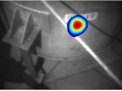
More and more, the decommissioning scenarios are evaluated using virtual reality modeling. This approach allows taking into account the specific constraints of an operation without expose workers. Theses simulations can include the data obtained from a gamma camera (location of a source, activities). The radiological characterization of large facilities is an example of use of inspection robots on cables in order to optimize the operations that should take place into it. The radiological characterization of large facilities is an example of use of inspection robots on cables in order to optimize the operations that will
7
take place inside. The integration of a gamma camera must be performed taking into account particularly the principle of minimizing the mass of the inspection robot [6, 7].
Figure 5 - Source location by a gamma camera
Nowadays, 3D scanner technologies of large facility are available. These technology can be used to create CAD models of the inside installation. The collect data from a 3D scanner can then be used in a 3D virtual reality showroom facility. We find here the concept of virtual simulation of the dismantling scenarios. Furthermore, when we add to this virtual model, dataset as dose rates and source locations obtained by a gamma camera, we obtain a better knowledge of the initial state of a nuclear facility. These elements are important in the objectives to reduce cost and guarantee the schedules of D&D operations. A large amount of 3D scanner devices are available on the market with specific characteristics. And the integration of such technology has to done with the objectives to always minimize the size and weight of the inspection robot.
The use of robot systems implies the need to monitor its internal components. For instance, the temperature of the motors must to be known during an operation to avoid failure of the motor. In the case of our inspection robot as noted previously, the motor used to move the robot is outside the facility to inspect. However as noted previously, the behaviors of the electronic components have to be particularly monitored. This is why we schedule to integrate a dosimeter to prevent any failure of the electronic and thus anticipate its maintenance.
CONCLUSIONS
In this paper, the development of an inspection robot on cables suited for monitoring tasks in nuclear facilities is presented. The use of a robot on cables has various advantages: capacity to monitor lengthwise facilities while avoiding the possible constraints on the ground and with a secure path whose positions are perfectly controlled. This system ensures robustness and repeatability of measurements in terms of location while achieving a high level of safety and security. If the use presented in this paper is for an application in a hostile environment due to the radiation and contamination, we can perfectly imagine use this system in a less hostile environment. Indeed this system is suited for monitoring tasks in lengthwise facilities or with hard access and in which measurements are difficult to realize. The presented illustration provides a first level of standardization in severe environments: cables, transfer carriage and containment equipment. Today, the goal is to improve the current system for example in term of range or
8
for diversifying the environment of application by developing its modularity and for allowing the integration of rich features embedded in the system.
REFERENCES
1. AUTORITE DE SURETE NUCLEAIRE. « ASN report on the state of nuclear safety and radiation protection in France in 2013 », Report in English available at: www.french-nuclear-safety.fr.
2. R. BOGUE. « Robots in the nuclear industry: a review of technologies and applications», Industrial Robot: An International Journal, Vol. 38 Issue 2 pp. 113 - 118 (2011).
3. INTERNATIONAL ATOMIC ENERGY AGENCY. « Maintenance, surveillance and in-service inspection in nuclear power plants – Safety Guide », Safety Standards Series No. NS-G-2.6, Vienna, 2002.
4. L. BRUZZONE, G. QUAGLIA. “Review article: locomotion systems for ground mobile robots in unstructured environments”, Mechanical Sciences, Vol. 3, pp 49 – 62 (2012).
5. H. MASSON, J. C. BATAILLES-LANNES, J.P. MISTRAL, B. VIGNAU, J. MISRAKI and P. GEIDER. « Marcoule UP1 reprocessing plant first steps towards decommissioning », Waste Management Conference, February 27 - March 2, 2000, Tucson, Arizona, USA.
6. O. GAL, C. IZAC, F. LAINE, A. NGUYEN. « CARTOGAM: a portable gamma camera », Nuclear Instruments and Methods in Physics Research Section A: Accelerators, Spectrometers, Detectors and Associated Equipment, Vol. 387, pp 297 - 303 (1997).
7. M. GMAR, M. AGELOU, F. CARREL, V. SCHOEPFF. « GAMPIX: A new generation of gamma camera », Nuclear Instruments and Methods in Physics Research Section A: Accelerators, Spectrometers, Detectors and Associated Equipment, Vol. 652, pp 638 – 640 (2011).