HAL Id: cea-02456851
https://hal-cea.archives-ouvertes.fr/cea-02456851
Submitted on 27 Jan 2020
HAL is a multi-disciplinary open access
archive for the deposit and dissemination of
sci-entific research documents, whether they are
pub-lished or not. The documents may come from
teaching and research institutions in France or
abroad, or from public or private research centers.
L’archive ouverte pluridisciplinaire HAL, est
destinée au dépôt et à la diffusion de documents
scientifiques de niveau recherche, publiés ou non,
émanant des établissements d’enseignement et de
recherche français ou étrangers, des laboratoires
publics ou privés.
R. Ragona, A. Messiaen, J. Ongena, D. van Eester, M. van Schoor, J.-M.
Bernard, J. Hillairet, J.-M. Noterdaeme
To cite this version:
R. Ragona, A. Messiaen, J. Ongena, D. van Eester, M. van Schoor, et al.. A travelling wave array
system as solution for the ion cyclotron resonance frequencies heating of DEMO. Nuclear Fusion, IOP
Publishing, 2020, 60, pp.016027. �10.1088/1741-4326/ab504a�. �cea-02456851�
1
A TRAVELLING WAVE ARRAY SYSTEM AS
SOLUTION FOR THE ICRF HEATING OF DEMO
R. RAGONA*, A. MESSIAEN, J. ONGENA, D. VAN EESTER, M. VAN SCHOOR Laboratory for Plasma Physics, LPP-ERM/KMS
Brussels, Belgium
Email: Riccardo.Ragona@rma.ac.be J-M. BERNARD, J. HILLAIRET CEA, IRFM Cadarache
Saint Paul-lez-Durance, France J-M. NOTERDAEME*
Max-Plank-Institute fur Plasmaphysik Garching-bei-Munchen, Germany
*Ghent University, Applied Physics Department, Ghent, Belgium
Abstract
Travelling Wave Array (TWA) antennas distributed along the periphery of the tokamak are presently considered as Ion Cyclotron Resonance Frequencies (ICRF) heating solution for the DEMO reactor. Compared to the conventional ICRF antenna systems currently in use or designed for future machines like ITER, the TWA consists of antenna sections integrated in the breeding blanket scattered around the machine, each one fed through a variable coupler in a resonant ring configuration. Previous modelling of an antenna system for DEMO with 16 quadruple TWA sections of 8 straps shows that a power capability exceeding 50 MW can be obtained in the frequency band of interest using the reference low coupling plasma profile of ITER. The described system optimizes the coupling to the plasma by providing a large number of radiating elements, which results in enhanced antenna directivity hereby decreasing the antenna power density. This results in a maximum strap voltage amplitude of only 15 kV and maximum inter-strap voltage amplitude of 18 kV. The generators remain matched for all loading conditions: the system is totally load resilient. Following the recommendation of the work package heating and current drive (WPHCD) Review Panel, a TWA ICRH system consisting in fewer sections concentrated in front of the equatorial ports is analysed in this paper and compared to the previous design. Reducing the number of sections increases the power density and its associated voltages. To couple 50 MW on the ITER density profile, voltages up to 30 kV are now required. Some aspects like the coupling between sections and its repercussion on the feeding network are briefly discussed. To assess the feasibility of the TWA fed by a resonant ring as ICRH system for a DEMO reactor, a test on an existing medium size tokamak is under study.
1. INTRODUCTION
To heat the core of a large fusion machine Ion Cyclotron Resonant Heating (ICRH) is a logical first choice as it enables coupling auxiliary heating power directly to the ions. In addition, ICRH does not suffer from a cut-off frequency and is thus an ideal method to heat plasmas at very high density, as projected for DEMO. A drawback of ICRH, however, is the difficulty of coupling large amounts of power through the plasma boundary without exceeding the voltage standoff of the antenna(s) located along the wall. This is because most of the RF wave (kz,
ky) spectrum (z along the toroidal direction, y along the poloidal one) excited by the antenna, located at the wall,
is evanescent up to a cut-off plasma density. The latter is an increasing function of |kz| and |ky|. For a given
plasma profile and ion mix, the antenna coupling can be increased by tailoring the spectrum through the phasing an array of toroidal straps such that to concentrate the excitation near low values of |kz| and |ky|. However, the
value of |kz| cannot be too low: it must exceed the vacuum propagation coefficient k0, to avoid the excitation of
so-called coaxial modes, and it must lead to good central power deposition for the chosen heating scheme. The coaxial modes are waves propagating between the wall and the plasma boundary, leading to edge power deposition. For this reason they should be avoided. The peaking of the ky spectrum around ky = 0 is obtained by
straps of sufficient length and with approximately constant current in the poloidal direction. High fields are required for the high power to tunnel through this evanescence layer, for the foreseen reactor parameters. A final request for the ICRH system is to be load resilient in order to continue to deliver the power in presence of fast changes of antenna loading due to ELM’s.
In order to clarify for the reader the difference between a conventional ICRH antenna system and a TWA for their application to the reactor, we present a short comparison between the two concepts.
An in-port plug-in antenna similar the one in its final development for ITER;
A large power density and its associated large voltages and currents characterize the first option
.
It is an adaptation to DEMO of the ICRF in-port system of ITER with its feeding network [1,2]. The system has been optimized in the following way: it is constituted of 8 effective long straps with nearly constant current amplitude. Three short straps fed in parallel by means of a 4-port junction constitute the effective long strap. The frequency response of the 4-port junction is adapted to cover the ITER frequency band (40-55 MHz) by a well-positioned service stub [3]. The triplet array is arranged in 4 poloidal columns of triplet pairs. Each poloidal triplet pair is fed by its own power source through a 3dB hybrid to insure load resilience and through matching-decoupling network. Pre-matching stubs are adjusted to decrease the antinode voltage from the output of the plug-in up to the decouplers and the main matching system. The decouplers are used to counteract the power transfer between triplets due to mutual coupling. They are also used to feedback control the antinode voltage amplitude in the lines at the input of the 4 port junctions. Double stub tuners are used as main matching circuits. Vertical Septa are placed between the 4 triplet pairs to decrease mutual coupling and avoid too large constraints to the decouplers network. Special care is taken to have an appropriate RF grounding of the plug-in to the vessel. The toroidal phasing control of the 4 poloidal triplet pairs is obtained by the phasing of the generators. The poloidal phasing in quadrature of each triplet pair is due to the hybrids. The voltage antinode amplitude at the plug-in input of the decoupler-matching network is used to control the antenna current amplitude. An automatic system for the adjustment of the complete matching-decoupling network has been developed and tested at LPP on an ITER mock-up in presence of variable dummy load [4]. It uses 23 simultaneously motorized feedback loops.A Traveling Wave Array antenna (TWA).
To reduce the antenna power density and the associated high voltage in low coupling conditions, TWA antennas distributed around the periphery of the tokamak are presently considered for the DEMO reactor [5,6]. A TWA section consists of an array of parallel grounded straps, each terminated by a self-integrated tuning reactance. Due to the inter-strap mutual coupling, the TWA array constitutes a passive travelling wave structure interacting with the plasma in front of it [7]. The absence of vertical septa between the straps can substantially increase the coupling of the TWA to the plasma. Those septa are inserted on purpose in the classical ICRH antennas to reduce the inter-strap mutual coupling and the resulting matching problems. The interested reader will find more details on the comparison between the ITER launcher and a TWA section in [8]. The TWA network acts as a band-pass filter between its input and output strap connections, i.e. it can sustain the propagation of a traveling wave in a frequency band determined by its geometry. When operated inside its band, it is equivalent to a lossy transmission line section loaded by the coupling to the plasma and the ohmic losses. The inter-strap phase difference can be adjusted by the choice of the frequency inside its frequency band. If the TWA section is fed in resonant ring configuration, the non-radiated part is recirculated of its input power. This TWA antenna system has the advantage to combine many interesting properties [7-11]:
(a) It optimizes coupling to the plasma. The TWA array coupling scales as the ratio nstr/Sz of the total number
of straps nstr to their inter-distance Sz. The coupling of msec sections of TWA arrays scales as msecnstr/Sz.
Furthermore, the radiated power capability per strap, for a given strap voltage, is also larger (e.g. factor 2 for |k//|=3 m-1) than for a conventional antenna, as e.g. in the ITER design, due to the removal of the vertical
septa between the straps.
(b) The generators remain matched for all loading conditions and therefore the system is totally load resilient. (c) The radiated power k// spectrum is very selective and can be tuned to concentrate the power in that part of
the spectrum that allows a sufficiently large tunnelling through the evanescent zone and at the same time good absorption in the core plasma.
(d) At ring resonance, an almost 100% power absorption by the plasma and associated negligible absorption in the loads of the hybrid couplers can be obtained for a broad range of loading resistances and frequencies. The voltage on the elements of the TWA adjusts itself such that all the power provided by the generators is delivered to the plasma and ohmic losses.
(e) The Voltage Standing Wave Ratio (VSWR) remains close to 1 (i.e. there is a negligible amount of power reflected back from the antenna) in all parts of the feeding circuit, in contrast to standard antennas. For the TWA system this aspect ensures a lower line voltage for a given coupled power and leads therefore to a smaller transmission line size or improved reliability.
3 Previous modelling of an antenna system for DEMO of 16 quadruple TWA sections of 8 straps shows that a power capability exceeding 50 MW can be obtained in the frequency band 46-54 MHz for a maximum strap voltage amplitude of only 15 kV and a maximum inter-strap voltage amplitude of 18 kV using the reference low coupling plasma profile of ITER (hereafter “ITER-2010-low” [12]). Presently the TWA system presented in [7,10] has been successfully tested on a scaled mock-up loaded by a salty water dummy load. To assess its feasibility for a DEMO reactor, a test on an existing tokamak is needed. Indeed, the TWA concept has been only partially tested for fast wave current drive at high harmonic cyclotron frequencies (200 MHz) [13] and a convincing test for standard IC minority heating scenarios is still missing. Another experimental verification of some properties of the combline TWA at very high cyclotron harmonic frequency (500 MHz) has been reported in [14].
To follow the recommendation of the Review Panel of the work-package heating and current drive (WPHCD) of PPPT (power plant physics and technology), in this paper the case of an ICRH system made of TWA sections grouped in 4 sectors of the machine is analysed. Each sector is made of 3 or 4 TWA sections. The total power is fixed at 50 MW and the required voltage on each strap is computed when the arrays are loaded by the ITER-2010-low profile. A first section describes briefly the target scenario defining the driving frequency for the array’s design. A second section introduces the new configuration and present the preliminary results for the RF coupling performances. A third section briefly discusses the proof of principle on a medium size tokamak (e.g. WEST). Discussion and conclusions are drawn in the last section.
2. SCENARIO
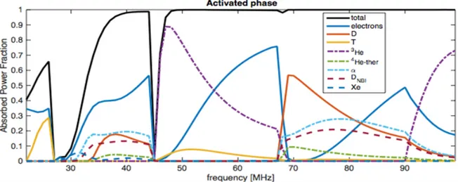
The target heating scenario for the computation made in this paper is minority heating of 3He and second harmonic heating of T (ω = Ω3He = 2ΩT); the key concentrations are X[3He] = 3%, X[D] = X[T]. Fig. 1 shows
the power absorption fraction, computed with TOMCAT [15], for the different components of the plasma in the activated phase, i.e. in presence of fusion born alpha particles, 10% in total, of which 1% fast. The parameters used are: a major radius of 9m, a minor radius of 3m, a central density of 10!"m!!, a central ion and electron
temperature of 28 keV and a toroidal number of 50 (that corresponds to a 𝑘!≈ 4 m-1). The figure shows the
presence of a suitable window starting at 40 MHz, where the 3He and T cyclotron resonance layers enter in the
confined plasma from the low magnetic field side (LFS), and ending at 68 MHz where the layers exit on the high magnetic field side (HFS). Fusion born alpha particles have a wide Doppler shift and absorb power well away from their cyclotron layer. Fortunately they are not playing a role in the abovementioned band, while they play a key role in the frequency ranges just below and just above the preferred one. Electrons are absorbing a considerable fraction of the power; this is a drawback of the big machine size and is a consequence of the fact that – unlike cyclotron heating – electron Landau damping and transit time magnetic pumping are not localised but only require the thermal velocity of the electrons and the wave phase velocity to be of similar size. An optimal frequency range for heating is then in the band 50 MHz to 55 MHz, which will be used in what follows. A complete analysis of the possible scenario with all the details will be published soon [16].
3. TRAVELLING WAVE ARRAY SYSTEM
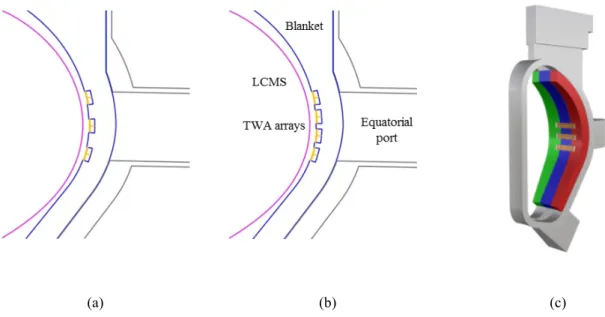
The design power for the DEMO ICRH system is set to 50 MW. It is assumed here to be launched from 4 equatorial ports of the machine. The aim is to evaluate the performance of a TWA system using only the equatorial port for the feeding. Installation and remote handling aspects are not discussed here. The system proposed consists of 12 or 16 TWA sections displaced poloidally in groups of 3 or 4 for each equatorial port, as shown in Fig. 2. The figure depicts a detail from an elevation cut in the middle of one equatorial port of the vessel for the triplet case (Fig. 2a) and quartet case (Fig. 2b). The cross-section of the central blanket module (blue) shows the poloidal location of the TWA sections. An overall view showing the three external blanket modules (green, blue and red), one vacuum vessel sector and the TWA sections for the triplet case embedded in the blanket modules is presented is Fig. 2c.
(a) (b) (c)
FIG. 2. Elevation cut through an equatorial port for the two cases analysed. (a) three poloidally distributed sections, (b) four sections. (c) view of the blanket modules, one vacuum vessel sector and three TWA sections embedded in the blankets modules.
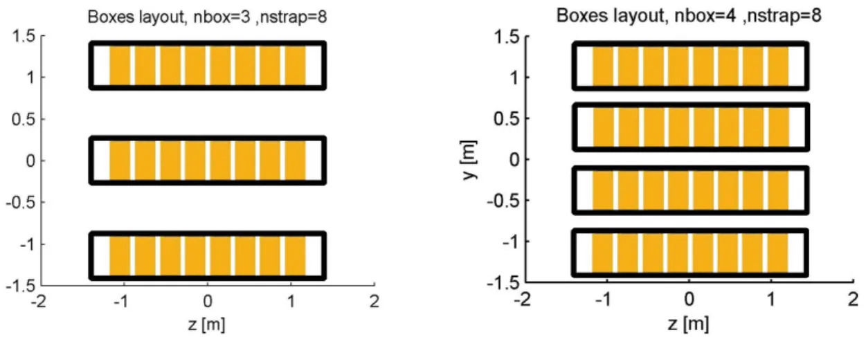
Each section is made by an array of 8 straps of the T-type, i.e. grounded centrally by a post. The two ends of each strap are terminated by an integrated capacitor. The dimensions of each array are: strap width of 20 cm, strap height of 54 cm, strap inter-distance of 30 cm, box depth of 21 cm and total box length of 2.80 m. The aperture of a section measures 1.54 m2. The power requirement per group/port is 12.5 MW. For the triplet, the power per section amounts to 4.17 MW with a power density of 2.7 MW/m2 while for the case of the 4 arrays
the power per section is 3.13 MW with a power density of 2.03 MW/m2. The plasma last close magnetic surface (LCMS) is at slightly different distances from the antennas. An inspection of Fig. 2a,b reveals that the lower arrays are closer to the LCMS (purple line). For the analysis, the mean value of 23 cm is assumed. The RF performances of the two cases are investigated by means of the recently upgraded ANTITER-II code [17]. In absence of an official DEMO plasma density profile that covers also the scrape off layer (SOL), the chosen profile in front of the antenna is the ITER-2010-low. It should be noted that this profile represents a low coupling scenario. The amount of power that can be coupled depends heavily on the density profile; mainly on the antenna/cut-off density distance and on the slope of the profile around that location. Thus the results presented here are valid only for the particular profile used. A different profile could increase the coupled power even by an order of magnitude [18]. The driving frequency is set to 50 MHz, as discussed in the previous section. The geometry of the two cases is shown in Fig. 3. The triplet has an inter distance between the sections of 60 cm, larger than the 22 cm of the 4 sections case, allowing a better isolation of the feeding networks. The maximum poloidal extent is limited by the height of the vessel port. The feeding of each section is made by a resonant ring. The feeding lines, 2 for each section, are routed through the equatorial port. Even using large
5 diameter coaxial transmission lines (30 cm) most of the space of the port is left free and could be used by other systems/diagnostics. The three sections show a fairly good isolation between them. On the contrary, the 4 sections are more coupled together due to their reduced inter-distance. Further analyses are required to characterise the complete feeding network for these two cases. The results reported here correspond to the performances of the antenna only, excluding the effect on the generators.
FIG. 3. Geometrical layout of the TWA section groups considered in this analysis. The maximum poloidal extension (y direction) is limited here by the height of the vessel port.
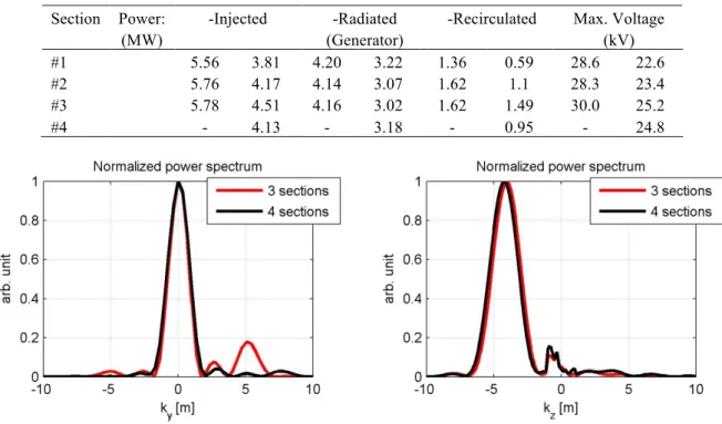
The voltages required to obtain the power of 4.17 MW/section, for the triplet case, and of 3.13 MW/section, for the 4 section case, are shown in Fig. 4 along with the inter-strap phasing. The voltage values are higher (factor 2) w.r.t to the previously presented antenna design because the number of sections is drastically reduced. The former design uses 32 sections while the one presented here uses 12 or 16 sections. The injected, radiated and recirculated powers for a single sector are tabulated in Table 1. The maximum voltage in each array is tabulated for convenience (cf Fig. 4.). Ohmic losses in the antenna structure and in the feeding lines are not considered here so the radiated power corresponds to the power delivered by the generator. The recirculated power is added to the generator power by means of the resonant ring and injected to the array. The normalised power spectra for the two cases analysed in this paper are presented in Fig. 5. This corresponds to the case where all the arrays are fed in the same direction and with the same phasing. The large directivity in the toroidal direction is due to the large number of straps in each section while the directivity in the poloidal direction results from the interaction of the poloidal sets. Different phasing could be easily investigated.
TABLE 1. POWER CIRCULATION AND MAX VOLTAGE PER SECTOR Section Power:
(MW)
-Injected -Radiated (Generator)
-Recirculated Max. Voltage (kV) #1 5.56 3.81 4.20 3.22 1.36 0.59 28.6 22.6 #2 #3 #4 5.76 5.78 - 4.17 4.51 4.13 4.14 4.16 - 3.07 3.02 3.18 1.62 1.62 - 1.1 1.49 0.95 28.3 30.0 - 23.4 25.2 24.8
FIG. 5. Normalised (left) poloidal and (right) toroidal power spectra for the two cases considered. Both spectra shows a high directivity. The poloidal spectra show the effect of the multiplicity of the array.
4. PROPOSED PROOF OF PRINCIPLE ON MEDIUM SIZE TOKAMAK
A proof of principle of the TWA concept for ICRH on a medium size tokamak is a needed step in order to be accepted in the conceptual design of DEMO. The TWA concept was presented in the early ’90 [9,19] and tested only for fast wave current drive (FWCD) at high frequency [13,14]. More recently, the travelling wave antenna concept has found new interests for application in the helicon current drive frequency domain [20,21] and in lower hybrid frequency range [22]. Despite that, a test for ICRH in a metal wall machine, in steady state operation, has never been done before. Those two conditions are fundamental for a reactor. For this reason, a test on WEST is presently under consideration [23]. It uses the equivalent of a single section of the DEMO proposed system, independently of the configuration (32 or 12/16 sections). WEST is the ideal machine for this task: it is a metal wall machine, it is designed for steady state operation, it is already equipped with a powerful ICRH system, it has dedicated diagnostics and the WEST team has a long experience in ICRH physics, engineering and technology. A test on WEST will allow validating experimentally the performances expected from a TWA in reactor relevant conditions. Due to the transformation from a limiter circular configuration to a divertor configuration [24], WEST has space available inside the vacuum vessel to install a relatively large antenna as the TWA. The relative position of the TWA w.r.t. the plasma can be adjusted in the design phase to be as large as 10 cm w.r.t. the LCMS of the reference plasma scenario. This mimics the large antenna-plasma distance expected for DEMO. Moreover, the design and exploitation of such system will allow extrapolating RAMI (reliability, availability, maintainability, inspectability) parameters that are key factors during the design of a fusion reactor like DEMO. A preliminary RAMI analysis is presented in [23] but more complete analysis will be published elsewhere. Fig. 6a presents an artist’s view of the TWA system for WEST. The location inside the machine will allow comparing the TWA with the classical antenna design already installed.
Another proposal consists in a set of TWA antennas to be installed in the T-15MD (fig. 6b) device in construction at the National Research Centre Kurchatov Institute in Moscow [25]. T-15MD represents a good opportunity to integrate a TWA in a tokamak from the design phase. Due to the availability of space all around
7 the torus, a set of 4 independent TWA could be installed toroidally, just below the equatorial ports. In this case, the mutual effect of a toroidal series of arrays could be experimentally tested. The plasma-antenna distance could be adjusted to DEMO like edge conditions, thus representing another possibility to test the response and performance of a TWA in various coupling conditions.
FIG. 6. Artist’s views of the proposed proof of principle of the DEMO TWA ICRH system on (a)WEST with two arrays in the poloidal direction and (b)T-15-MD with multiple arrays in the toroidal direction. Only half of the machine is
shown.
5. DISCUSSION AND OUTLOOK
A system made of 32 T-sections was presented previously with a power capability, when loaded by the ITER 2010 low coupling profile, exceeding 50 MW at a maximum strap voltage of 15 kV and at a power density of less than 1 MW/m2. Following the recommendation of the WPHCD Review Panel, a new TWA system that fits
into the space of few (here considered 4) equatorial ports is analysed and presented here. This constraint reduces the number of elements from 32 to 12-16 thus increasing the power density and the associated strap voltages. A total power of 50 MW with a 4 sector system results in a power per section of 12.5 MW. Two cases are considered: 3 and 4 vertically displaced sections. TWA sections could not be placed too close together poloidally without incurring in coupling of the feeding networks that results in the use of decoupling-matching networks, like for the classical designs. To couple 4.17 MW, each section of a triplet requires voltages in the order of 30 kV which is decreased to about 25 kV for the four sections with a unit power of 3.13 MW. Further optimisations are possible by changing the geometry of the arrays, e.g. increasing the number of strap and varying their dimensions. It is very important for the reader to keep in mind the high sensitivity of any ICRH system to the plasma density profile. For this reason, the results presented here have to be considered as a worst case scenario. Substantial improvements, i.e. lower voltage for the same amount of coupled power, could be achieved by using a different profile.
Each section, that is an independent antenna box which measure approximately 2-2.5 m, could be potentially deployed in the machine from the equatorial port. It could be mechanically connected only to the central blanket module remaining electrically isolated from the neighbouring (blanket) modules. In the equatorial plane, the toroidal extension of a blanket module is of about 1.5-1.8 m. Due to the small lateral emboss (only a fraction of the antenna box total length), the box should not suffer from mechanical problem in case of disruption forces. A dedicated analysis to assess the magnitude of those forces is required before proceeding with the RF design validation. Connections to the RF power feeding lines and cooling pipes could be performed from the equatorial port by a dedicated remote handling procedure. Each TWA section is made of the same material as the first wall of the machine so no particular issues are expected for what concern material reliability and activation.
To overcome the increased power density and voltage resulting from the configuration presented in this paper, a different layout for the arrays could be foreseen. Array sections could be placed on top and at bottom of each equatorial port in order not to interfere with any other system that require ports (e.g. EC, NB, diagnostics) thus increasing the number of sections back to 32 (one for each machine sector, i.e. 16 in the DEMO version here considered). Sections will be then slightly more vertically (poloidally) displaced from the equatorial plane. An assessment of the power deposition profiles in the core plasma is in progress. Analogously, 32 sections could be
arranged in the equatorial plane in the space between two ports, ideally directly integrated in the blanket. On this particular aspect, a research activity has been started. Having a large number of sections has the advantage of reducing not only the power density but also the required size for the feeding lines. This means a reduced impact on the breeding blanket where those lines have to be routed. In an extreme but still reasonable case, TWA sections of the size of a single blanket module could be designed to be operated at very low power. A fast estimate could be made considering that each sector of the machine is made by 3 blanket modules, for a total of 48, giving a power per module of 1.04 MW. When considering two arrays of 1.5 m x 0.55 m the resulting power density is 0.63 MW/m2. It can be shown that the voltages required by this compact array are in the range of 15
kV, when loaded by the ITER-2010-low profile.
TWA antennas consist of large arrays of toroidally adjacent radiating elements. The ratio antenna size vs. machine size and their intrinsic characteristic as a low power density array made them less attractive in the past. Several TWA have been tested at higher frequencies where that ratio is more favourable for integration in the vessel. In a larger machine like a reactor, this ratio is low and decreases even further as the machine size increases, making integration more feasible. In present day machines, the two devices with favourable conditions for a TWA system test are WEST and T-15MD.
Two complementary tests are being proposed. Both machines will allow exploring the performance of the TWA concept for larger than usual antenna-plasma distances. This is one of the key points for this technology in view of a reactor. On WEST, a direct comparison between the TWA and a traditional ICRH antenna can be performed simultaneously on the same target plasma. This will allow assessing the characteristics of a TWA and comparing the plasma response and the near field effects of both antenna designs. On T-15MD, the mutual effects of a toroidal series of adjacent TWA can be assessed in experimental conditions that can be extrapolated to the reactor. Two slightly different topologies of TWA, T-type and toroidal series for T-15MD or L-type and double array for WEST, can be tested and compared providing results directly applicable for the DEMO design. We are not aware of any specific physics or engineering showstoppers that prevent the use of a TWA in a fusion machine. As a TWA is generally larger than a classical compact array, it is beneficial to consider the integration of such an antenna with its larger spatial extent in the beginning of the design of a new device. An example is the NSTX HHFW antenna with its long (12 elements) phased array that covers one quarter (i.e. 90 degrees) of the machine circumference. This is similar to our proposal for T-15MD. For comparison, our WEST proposal covers a 45 degrees sector of the device.
A more compact TWA is possible by reducing the number of radiating elements. But in determining the optimal number of radiating elements, one has to consider the physical principles of power coupling by a TWA to the plasma.. The power injected by the feeding system on the first element of the antenna array is transferred, by mutual coupling, from element to element towards the end of the array. During its flow across the array, part of the power is radiated into the plasma. The ratio of the power radiated into the plasma to the power flowing across the array, is generally low. When a considerable amount of power reaches the end of the array (e.g. due to a too small number of radiating elements for the coupling conditions in the machine), this power has to be extracted from the antenna by a properly matched termination to avoid reflected power back to the array. This termination can be a dummy load, where the power is lost, or much better, a recirculation mechanism like the resonant ring we propose. Increasing the number of radiating elements will increase the power radiated into the plasma. For a sufficiently large number of elements, all power will be radiated in the plasma. In such a case there is no recirculated power. On the other hand, if the number of radiating elements is too large for given coupling conditions, then all RF power is already totally radiated in the plasma somewhere along the array. The remaining elements do not participate in coupling the power to the plasma and create an internally matched termination for the array. This is a non-optimal use of the in-vessel space.
In conclusion, a well-designed TWA system demonstrates simultaneously the following characteristics: it allows operation at low power densities at the antenna (i.e. low electric fields), (ii) it allows coupling the total RF power at large antenna-plasma distances (i.e. under low coupling conditions) and (iii) it is intrinsically load resilient. These are necessary characteristics for a large machine like DEMO, but they are also of interest for a medium size fusion device. The capability to couple MWs of RF power at a large antenna-plasma distance (e.g. 10 cm or more) with full load resilience and no need for a complex external matching systems are true assets that more than justify the efforts of its integration in present day and future fusion devices.
TWA arrays are a good option for an ICRH system in DEMO. They allow maximising the power coupling while reducing the high voltages (and associated EM fields) at the antenna aperture, thus reducing deleterious interaction with the SOL. Different layouts are possible to accommodate the reactor requirements in terms of
9 power capability, integration in the blanket and RAMI scoring. A test on a medium size tokamak is a necessary step to demonstrate the predicted beneficial properties of the TWA design.
ACKNOWLEDGEMENTS
This work has been carried out within the framework of the EUROfusion Consortium and has received funding from the Euratom research and training programme 2014-2018 under grant agreement No 633053. The views and opinions expressed herein do not necessarily reflect those of the European Commission.
REFERENCES
[1] B. Beaumont et al. 2017 EPJ Web of Conferences 157 02002 [2] P. Lamalle et al. 2013 Fusion Eng. Des. 88 6-8 517-520 [3] F. Durodié et al. 2014 Physics of Plasmas 21 061512 [4] D. Grine et al. 2011 Fusion Eng. Des. 86 6-8 978-981
[5] T. Franke et al 2018 IEEE Transaction on Plasma Science 46 1633-1640 [6] J.M. Noterdaeme et al 2019 Fusion Eng. Des. 146 A, 1321-1324 [7] R. Ragona and A. Messiaen 2016 Nucl. Fusion 56 076009
[8] A. Messiaen et al. 2016 Proc. 43rd EPD Conf. on Plasma Physics (Leuven, Belgium, 4-8 July 2016) Europhysics Conf. Abstracts Vol 40A, paper P2.066
[9] Moeller C.P. et al 1994 AIP Conference Proceedings 289, 323 [10] Messiaen and R. Ragona 2017 EPJ Web of Conferences. 157 03033 [11] R. Ragona and A. Messiaen 2017 EPJ Web Conferences. 157 03044 [12] S. Carpentier and R. A. Pitts 2010 Report ITER_D_33y59M_v2,3 [13] T. Ogawa et al. 2001 Nucl. Fusion 41 1767
[14] S. J. Wang et al 2017 Nucl. Fusion 57 046010
[15] D. Van Eester and R. Koch 1998 Plasma Phys. Control. Fusion 40 1949–1975 [16] D. Van Eester et al 2019 Nucl. Fusion 59 106051
[17] A. Messiaen and R. Ragona, 2019 Plasma Phys. Control. Fusion 61 044004 [18] A. Messiaen et al., 2011 AIP Conference Proceedings 1406, 89
[19] J. S. deGrassie et al., 1992 Proc. 17th Symposium on Fusion Technology (Rome, Italy, 14-18 September 1992) 457-461
[20] H.H. Wi et al, 2018 Fusion Eng. Des. 126, 67-72 [21] J.F. Tooker et al., 2017 Fusion Eng. Des. 123, 228-231 [22] JG. Jo et al, 2018 Physics of Plasmas 25, 082511 [23] R. Ragona et al., 2019 Fusion Eng. Des. 146 A, 854-857 [24] J. Bucalossi et al, 2014 Fusion Eng. Des. 89 7-8, 907-912 [25] J. Ongena et al., 2019Fusion Eng. Des. 146 A, 787-791