HAL Id: hal-01348480
https://hal.archives-ouvertes.fr/hal-01348480
Submitted on 24 Jul 2016
HAL is a multi-disciplinary open access
archive for the deposit and dissemination of
sci-entific research documents, whether they are
pub-lished or not. The documents may come from
teaching and research institutions in France or
abroad, or from public or private research centers.
L’archive ouverte pluridisciplinaire HAL, est
destinée au dépôt et à la diffusion de documents
scientifiques de niveau recherche, publiés ou non,
émanant des établissements d’enseignement et de
recherche français ou étrangers, des laboratoires
publics ou privés.
Electrical characterization and modeling of benthic
microbial fuel cells for energy harvesting
Armande Capitaine, T Chailloux, Gaël Pillonnet, Bruno Allard
To cite this version:
Armande Capitaine, T Chailloux, Gaël Pillonnet, Bruno Allard. Electrical characterization and
mod-eling of benthic microbial fuel cells for energy harvesting. 5e Journées Nationales sur la Récupération
et le Stockage d’Energie pour l’alimentation de microsystèmes autonomes (JNRSE’2015), May 2015,
Orsay, France. �hal-01348480�
Electrical characterization and modeling of
benthic microbial fuel cells for energy harvesting
A. Capitaine
1,2, T. Chailloux
1, G. Pillonnet
1, B. Allard
21 Univ. Grenoble Alpes, F-38000 Grenoble, France CEA, LETI, MINATEC Campus, F-38054 Grenoble, France 2 Univ. de Lyon, INSA Lyon, Ampère, UMR CNRS 5005, F-69621 Villeurbanne
Abstract— Microbial fuel cell (MFC) is a promising energy
harvester for supplying sensors in seafloors where solar, thermal and vibration sources are inadequate. Extensive efforts focus improvement of MFC biological and electrochemical capabilities while the electrical perspectives are poorly developed in literature. In order to promote MFC as energy scavenger, this paper explains the methods used to electrically characterize the specific MFC for seafloor conditions and the way to model its steady state operation close to the maximum power point. The method is applied to a compost-fed MCF delivering 5.7µW at 0.14V optimal output voltage. This work is the first step to efficiently apprehend the elaboration of an electrical harvesting interface.
Keywords—energy harvesting; microbial fuel cell I. INTRODUCTION
In addition to data processing in an eco-friendly way, harvesting energy in the surrounding environment is an advantageous alternative to conventional batteries for powering autonomously remote sensors. Besides solar, thermal gradient and mechanical vibration are widely used as primary energies. Less analyzed in literature, the microbial fuel cell (MFC) studied in this paper is an emerging technology that exploits catalysis properties of bacteria onto a couple of redox reactions, to convert chemical energy from sediment into electrical energy. The field of application is large regarding the wide range of organic substrates that can be used (organic rich sediment, compost, waste water) [1]. It is worth noting that they can be deployed in regions where any other energy harvesters would be inappropriate (seafloors, sewage works).
The MFC is a relatively mature concept but the generated power is not directly usable (typically less than 0.6V in open circuit) to power continuously low-power sensor node (around 10µW/cm² of electrode). These main limitations come from the redox potential involved in the MFC process and the slow bacteria activity. So far the related researchers have focused their works on optimizing the MFC electrochemical properties (electrode material and design, bacteria selection) in order to maximize the power density [1]. However only few of them study the MFC from an electrical point of view [2] i.e. how to characterize, model and efficiently extract the available electrical power from the MFC? A presumed reason would be that the field is widely covered by environmental science researchers rather than their counterparts in electrical domain. Yet actively capturing the energy with a power management unit is an essential step and can enhance tremendously the harvested power.
In order to elaborate an efficient harvesting circuit, it is crucial to electrically model the MFC. That is the focus of this paper for MFCs of very low electrical capabilities. Literature covers several characterization methods dedicated to MFC
electrochemical properties [3]. For example Cyclic Voltammetry (CV) is frequently used to study redox reactions and verify the electrodes performances. Concerning electrical characterizations, there are two main methods [3]: Polarization Curve (PC) which is the most extensively used technique for estimating static electrical performances and Electrochemical Impedance Spectroscopy (EIS) which is used to find the small-signal circuit model in a desired frequency range.
This paper reviews the main static methods, i.e. CV and PC, in order to clarify the application to electrical MFC characterization. Both methods were performed on an in-situ MFC and a Thévenin equivalent model was deduced.
II. METHODS AND MEASUREMENT A. MFC elaboration
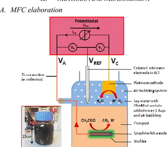
Fig. 1. Schematic diagram of the in-situ microbial fuel cell.
A schematic diagram of the lab-scale MFC is shown in Fig. 1. Bacteria catalyze the oxidation of the organic substrate on the Anode A while the oxygen is reduced at the Cathode C, inducing a transfer of electrons from A to C and thus energy generation [1]. Compost was chosen as the anaerobic bacterial medium in which 20-cm2 graphite-based anode is buried. In
the future the compost could be replaced by sand. A 3-cm2
platinum cathode is placed at the boundary surface of water, working with an air bubbling system to favor the oxygen reduction. 20mM of acetate were added in the 500mL water-filled reactor every 3 days during 40 days to boost the biofilm growth at the anode surface. This setup has been settled according to [4].
B. CV and PC characterisations Principle
The cyclic voltammetry consists in measuring the potential of each electrode separately using a reference electrode (REF
in Fig. 1, KCl-saturated Calomel electrode). To evaluate CV analysis, a potentiostat (Biologic VMP3) has been used. This device includes a controlled current source ICA (Fig. 1) placed
between the measuring electrode (called working electrode, WE) and the other electrode (counter electrode, CE). The device aims to measure the generated WE potential (vs REF) of the Cathode (VC) or Anode (VA).
The polarization curve results from the measurement of the voltage between the two electrodes UCA=VC-VA when the
current flow ICA varies. The PC can be obtained from the two
separated cathode and anode CV analyses, or by connecting different resistive output loads between VC and VA.
C. In-situ MFC measurements
Fig. 2 shows the cyclic voltammetry obtained on the lab-scale MFC reactor in Fig. 1 between open circuit (ICA=0) and
short circuit (ICA_max) conditions. Data are obtained using a
speed rate of 2mV/s and an initial open circuit measurement during 4 minutes. The open-circuit potential of the anode, VA,OC and cathode, VC,OC are equal to −0.73V and −0.23V
respectively, corresponding to the electrochemical activity. The positive current into the anode is due to the oxidation reaction, i.e. electron donor. Here the low slope of the cathode curve limits the current ICA (i.e. electron transfer) thus the
electrical energy harvesting.
Fig. 2. Cyclic voltammetry operated on the anode (green curve). Cyclic votametry performed on the cathode (blue curve).
Fig. 3. Polarization curve of the MFC measured by varying progressively the MFC output voltage by 2mV/s (solid blue curve). Polarization curve modelled by a Thevenin-equivalent electrical model (dashed blue curve). Output power (green curve).
The solid blue curve in Fig. 3 shows the MFC voltage UCA.
The open-circuit voltage, UOC, is 0.5V, confirming the need of
a harvesting interface to ultimately power sensors. This value could be extracted from Fig. 2 by subtracting the open-circuit
potential of the two electrodes, VA,OC and VC,OC. In
short-circuit conditions, the MFC delivers 97µA as shown in Fig. 3. This point is also correlated by the CV analysis when the polarizations of the two electrodes are equal (IA=−IC at 0.7V in
Fig. 2)
The green curve in Fig. 3 shows the calculated power UCA*ICA versus ICA. The Maximum Power Point MPP is
achieved at UCA,Opt=0.14V. At this point, the harvested energy
is 5.7µW corresponding to a power density of 2.9mW/m2.
III. MFCELECTRICAL MODEL
The solar, thermal or bio fuel-cell harvester is often modeled by a Thévenin equivalent circuit when operating close to MPP (Fig. 4) [5]. The polarization curve around MPP shown in Fig. 3 can be roughly estimated by a straight line (dashed line in Fig. 4) defined by Um=0.31 V and Rm=4 kΩ.
Fig. 4. Thévenin electrical circuit equivalent to the MFC close to MPP.
Identifying these two parameters is a crucial step to determine the value of Rh and maximize the power extraction
from the MFC. In fact the power received by a harvester interface is expressed as:
𝑃ℎ = 𝑈ℎ𝐼ℎ=
𝑅ℎ
(𝑅ℎ+ 𝑅𝑚)2𝑈𝑚 2= 𝑘𝑈
𝑚2
where k is the coupling coefficient between the harvester and harvesting interface.
The harvested power is optimized when k is maximized, i.e. Rh is equal to Rm. Then, the electrical interface (e.g. boost
converter) has to present an input impedance equal to the MFC output impedance Rm.
However the proposed model does not take into account the fluctuations due to environmental variations (temperature, substrate concentration, pH). Capacitive effects on the log term could also be hidden in the characterization process. The benefit of the intermittent harvesting studied in previous research is also not described here [6]. Further analysis will be done to propose a flexible and large signal model to overcome these limitations.
ACKNOWLEDGEMENT
Authors express many thanks to B. Erable for valuable ideas in the construction of the MFC reactor.
REFERENCES
[1] S. Venkata Mohan et al. “Microbial fuel cell: Critical factors regulating bio-catalyzed electrochemical process and recent advancements,” Renewable and Sustainable Energy Reviews, Dec. 2014.
[2] H. Wang, J.-D. Park, and Z. J. Ren, “Practical Energy Harvesting for Microbial Fuel Cells: A Review,” Environ. Sci. Technol., Mar. 2015. [3] B. E. Logan et al. “Microbial Fuel Cells: Methodology and
Technology†,” Environ. Sci. Technol., Sep. 2006.
[4] B. Erable et al. “Marine floating microbial fuel cell involving aerobic biofilm on stainless steel cathodes,” Bioresour. Technol., Aug. 2013. [5] S. Bandyopadhyay and A. P. Chandrakasan, “Platform Architecture for
Solar, Thermal, and Vibration Energy Combining With MPPT and Single Inductor,” IEEE Journal of Solid-State Circuits, Sep. 2012. [6] A. Dewan, et al. “Intermittent energy harvesting improves the