HAL Id: hal-03012819
https://hal.archives-ouvertes.fr/hal-03012819
Submitted on 18 Nov 2020
HAL is a multi-disciplinary open access
archive for the deposit and dissemination of
sci-entific research documents, whether they are
pub-lished or not. The documents may come from
teaching and research institutions in France or
abroad, or from public or private research centers.
L’archive ouverte pluridisciplinaire HAL, est
destinée au dépôt et à la diffusion de documents
scientifiques de niveau recherche, publiés ou non,
émanant des établissements d’enseignement et de
recherche français ou étrangers, des laboratoires
publics ou privés.
To cite this version:
Jaromir Mrazek, Eva Simeckova, Radomir Behal, Vadim Glagolev, František Vesely, et al.. Charged
particle activation facility in NPI CAS and in future GANIL/SPIRAL2-NFS. 2019 International
Conference on Nuclear Data for Science and Technology, May 2019, Beijing, China.
pp.17010,
�10.1051/epjconf/202023917010�. �hal-03012819�
Charged particle activation facility in NPI CAS and in future
GANIL/SPIRAL2-NFS
Jaromir Mrazek1,∗, Eva Simeckova1,, Radomir Behal1,, Vadim Glagolev1,, František Vesely1,, Milan Stefanik1,, Mitja
Majerle1,, Jan Novak1,, Martin Ansorge1,, Ivan Sivacek1,, Jitka Vrzalova1,, Xavier Ledoux2,, Francois de Oliveira
Santos2,, Ulrich Fischer3,, Axel Klix3,, Marilena Avrigeanu4,, and Vlad Avrigeanu4, 1Nuclear Physics Institute of the Czech Academy of Sciences, 250 68, ˇRež, Czech Republic 2GANIL CEA/DSM-CNRS/IN2P3, BP 55027, F-14076 Caen Cedex 5, France
3Karlsruhe Institute of Technology, 76344 Eggenstein-Leopoldshafen, Germany
4Horia Hulubei National Institute for Physics and Nuclear Engineering, P.O. Box MG-6, 077125 Bucharest-Magurele, Romania
Abstract.The proton, deuteron and alpha induced reactions are of a great interest for the assessment of induced radioactivity of accelerator components, targets and beam stoppers as well as isotope production for medicine and also to nuclear astrophysics. We present a new irradiation chamber for activation measurements, that forms a prolongation of long-term experimental activities using stacked-foil activation technique in NPI CAS, ˇRež. The chamber is based on an airlock system and is coupled to a pneumatic transfer system delivered by KIT Karlsruhe. This system is installed in GANIL/SPIRAL2-NFS and will be used for proton, deuteron and alpha particle activation measurements with long- and short-lived isotopes.
1 Introduction
A good knowledge of charged particle reaction cross sec-tions is important in number of cases, we name two, here: (a) construction, operation and decommissioning de-vices like ITER/DONES for IFMIF/DEMO - activation of construction materials, activation of accelerator com-ponents (targets, accelerator cavities, beamstops, etc.).
(b) improvements of the reaction models and under-standing the underlying physics, that helps to make predic-tions in combinapredic-tions of projectiles, targets and energies, where the data are missing or that are not experimentally accessible.
The experimental data are organized into large open access databases (e.g. EXFOR [1]) and are used - together with complex calculations based on theoretical models - to build open access libraries (e.g. TENDL [2]). An impor-tant part of the efforts, the underlying model parameters, obtained from interpretations are organized and kept in li-braries for building databases and other use (e.g. RIPL [3]). These efforts offer a framework of systematic and consistent approach also for other investigations in nuclear reactions.
A specific case, where more experimental data are needed and a theoretical interpretation is necessary to shed light on the reaction mechanism are reactions with a deuteron projectile. Where a direct processes compete with compound ones and where a breakup contributions play an important role. Number of works were already done to coherently describe the complex activation data in
∗e-mail: mrazek@ujf.cas.cz
the past (e.g. [4–8]). Another theoretical challenge is a prediction of population of isomeric states. Their impor-tance is emphasized in cases, where they decay to a dif-ferent daughter nucleus than the ground state. Such exper-imental measurements by activation can become difficult, when the isomer half-life is shorter or comparable to the time necessary for manipulation with the activated sample. While the number of systematic measurements and theoretical explanations were performed in the last decades, that have improved our knowledge and extended the available databases, there are still reactions, where the actual systematic measurements are difficult and thus very limited or non-existing. One of the important cases are the reactions leading to short-lived products. The aim of this paper is to introduce the complex system for mea-surements of both short-lived and long-lived isotopes in NFS [9] (Neutrons For Science) laboratory in GANIL-SPIRAL2.
2 Activation setup in NPI CAS
Nuclear Physics Institute of the Academy of Sciences of Czech Republic operates two cyclotrons: light particle, variable energy U-120M cyclotron (currents from nA to tens of µA) and a new high current (up to 300µA) pro-ton cyclotron TR24 (see the table 1). The operation of the cyclotrons is supported by the project CANAM (Center of Accelerators and Nuclear Analytical Methods) [10] of MEYS and RDI OP of EU.
The traditional charged particle activation setup used in NPI CAS consists of a stack of foils to be measured that are interleaved by monitoring foils (e.g. aluminium
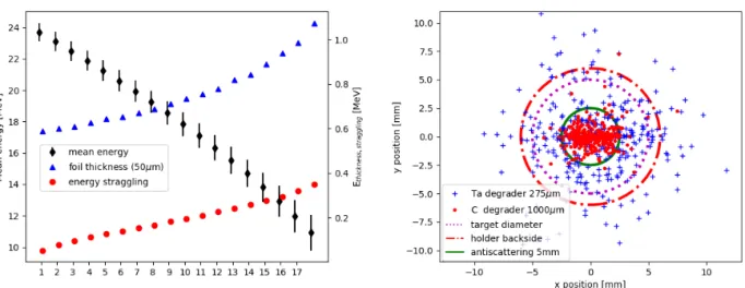
Figure 1. Left panel: a stacked foil simulation - an illustrative case of a proton beam on stack of 50 µmnatFe foils. Foil number is on x-axis, mean energy in the foil (black diamonds) is on the left y-axis), a foil thickness in terms of energy (blue triangles) and an energy straggling (red circles) are on the right-side y-axis. Right panel: A proton beam deposition simulation for Irradiation Chamber beam-target setup after 1 mm thick carbon degrader. The deposition is drawn at the backside of the sample holder. The distance between the degrader and the activation foil was 28 mm. The beam after the carbon degrader looses 5 MeV and is concentrated at the center (red dots). The beam spread for tantalum degrader (blue crosses) is shown for a comparison. The anti-scattering size is only depicted (a green circle) and was not included in the simulation.
Table 1. Beam energies in [MeV] of U-120M and TR24 cyclotrons (the second row is for TR24) in NPI CAS.
protons deuterons 3He 4He
6-38 11-20 16-53 22-40
18-24 – – –
[4]), that (a) make sure that there is no unobserved parti-cle exchange between neighbouring foils and that (b) the complete chain of procedures - from the beam energy and current measurement till detector efficiency calibration - is correct.
This method enables a simultaneous measurement of a number of data points. The energy losses and energy straggling have an impact on precision of (especially) low energy data points (see the left panel of figure 1). In measurements of short-lived isotopes with a stacked foils method, one needs to find a compromise between handling possibility of the accumulated activity and accessibility of shorter-lived isotopes. The stacked foils method was suc-cessfully applied in a number of experiments ([4–8]).
3 NFS at GANIL/SPIRAL2
A laboratory NFS (Neutrons For Science) in GANIL/SPIRAL2 was already presented elsewhere [9]. Despite its name, NFS laboratory will open new oppor-tunities also in activation by charged particles. Initially, light ion beams (p, d, α) are expected to be available with a maximum current 50 µA (a limit allowed for NFS, the maximum reachable current is 5 mA). The available energies are displayed in the table 2.
In the next section, we present the system for irradia-tion by charged particles for SPIRAL2/NFS, that was built
Table 2. Beam energies in [MeV] of LINAC accelerator of GANIL/SPIRAL2.
protons deuterons 3He 4He
0.75 - 33 1.5 - 40 2.25 - 72 3 - 80
within a program SPIRAL2-CZ, that is a framework of a Czech participation in GANIL/SPIRAL2.
4 Irradiation Chamber system
The need of construction of the new system for charged particle activation stems primarily from the limitations of deuteron beams in NPI CAS (see the tables 1, 2) and a simultaneous need of extension of the experimental possi-bilities. The demands for the construction of the system were based on long term experiences from NPI CAS and specific mode of operation in GANIL/SPIRAL2 NFS. A transport of a stack of foils between a beam in vacuum and storage was initially requested.
Further demands were defined, as a new technological solution and thus new abilities appeared:
• an irradiation of a single foil to measure short half-lives • a sub-minute transport time from the irradiation to the
detector
• a possibility of the fast change of the beam energy • a basic information on the beam quality on-line • a remote operation due to imposed safety restrictions
The selected solution was based on an airlock system coupled to a pneumatic transport system. The airlock sys-tem (in figure 2) is composed of two vacuum chambers: 2
Figure 1. Left panel: a stacked foil simulation - an illustrative case of a proton beam on stack of 50 µmnatFe foils. Foil number is on x-axis, mean energy in the foil (black diamonds) is on the left y-axis), a foil thickness in terms of energy (blue triangles) and an energy straggling (red circles) are on the right-side y-axis. Right panel: A proton beam deposition simulation for Irradiation Chamber beam-target setup after 1 mm thick carbon degrader. The deposition is drawn at the backside of the sample holder. The distance between the degrader and the activation foil was 28 mm. The beam after the carbon degrader looses 5 MeV and is concentrated at the center (red dots). The beam spread for tantalum degrader (blue crosses) is shown for a comparison. The anti-scattering size is only depicted (a green circle) and was not included in the simulation.
Table 1. Beam energies in [MeV] of U-120M and TR24 cyclotrons (the second row is for TR24) in NPI CAS.
protons deuterons 3He 4He
6-38 11-20 16-53 22-40
18-24 – – –
[4]), that (a) make sure that there is no unobserved parti-cle exchange between neighbouring foils and that (b) the complete chain of procedures - from the beam energy and current measurement till detector efficiency calibration - is correct.
This method enables a simultaneous measurement of a number of data points. The energy losses and energy straggling have an impact on precision of (especially) low energy data points (see the left panel of figure 1). In measurements of short-lived isotopes with a stacked foils method, one needs to find a compromise between handling possibility of the accumulated activity and accessibility of shorter-lived isotopes. The stacked foils method was suc-cessfully applied in a number of experiments ([4–8]).
3 NFS at GANIL/SPIRAL2
A laboratory NFS (Neutrons For Science) in GANIL/SPIRAL2 was already presented elsewhere [9]. Despite its name, NFS laboratory will open new oppor-tunities also in activation by charged particles. Initially, light ion beams (p, d, α) are expected to be available with a maximum current 50 µA (a limit allowed for NFS, the maximum reachable current is 5 mA). The available energies are displayed in the table 2.
In the next section, we present the system for irradia-tion by charged particles for SPIRAL2/NFS, that was built
Table 2. Beam energies in [MeV] of LINAC accelerator of GANIL/SPIRAL2.
protons deuterons 3He 4He
0.75 - 33 1.5 - 40 2.25 - 72 3 - 80
within a program SPIRAL2-CZ, that is a framework of a Czech participation in GANIL/SPIRAL2.
4 Irradiation Chamber system
The need of construction of the new system for charged particle activation stems primarily from the limitations of deuteron beams in NPI CAS (see the tables 1, 2) and a simultaneous need of extension of the experimental possi-bilities. The demands for the construction of the system were based on long term experiences from NPI CAS and specific mode of operation in GANIL/SPIRAL2 NFS. A transport of a stack of foils between a beam in vacuum and storage was initially requested.
Further demands were defined, as a new technological solution and thus new abilities appeared:
• an irradiation of a single foil to measure short half-lives • a sub-minute transport time from the irradiation to the
detector
• a possibility of the fast change of the beam energy • a basic information on the beam quality on-line • a remote operation due to imposed safety restrictions
The selected solution was based on an airlock system coupled to a pneumatic transport system. The airlock sys-tem (in figure 2) is composed of two vacuum chambers:
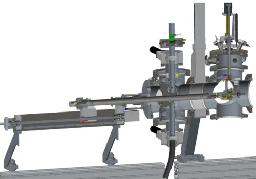
Figure 2. The Irradiation Chamber. It is composed of two vacuum chambers separated by an interlock valve (light gray). The rightmost part is permanently in the beamline and it contains a beam-target system. The left part contains a system for receiving/sending samples and is equipped with a manipulator. Two sample holders are depicted in green - one is waiting for receiving (in the middle) and the other is in the beam position (on the right).
Figure 3. Beam-target system. Beam direction is from the left, collimator, twelve position degrader,
anti-scattering-electrode.
one is equipped by a beam-target system and is perma-nently a part of the NFS beam-line. The other one is equipped by a sample receive/send system and a manipula-tor, that transfers a sample to/from the beam-target system of the first chamber.
Beam-target system
The beam-target system (see figure 3) consists of • an entrance collimator
• a cooled rotating degrader with twelve selectable posi-tions
• an anti-scattering collimator - electrode • a sample lock system with a suspension • a cooled Faraday cup
The beam is designed to have pencil-like characteris-tics with 4 mm diameter of the core. The entrance collima-tor is isolated and has a current readout, so that the infor-mation on beam position/focus change is available online.
The degrader will allow for a fast change of beam energy (as the time needed for the energy change of the accelera-tor and subsequent magneto-optic tuning is yet unknown ) at the expense of the energy (and angular - see right panel of figure 1) straggling. The degrader is connected to the same cooling loop as the Faraday cup and the isolation better than 500 MΩ is maintained. The degrader has its own electrical readout electrode. The third element down-stream is an anti-scattering collimator-electrode, that has several functions: (a) to remove eventual particles scat-tered by collimator or degrader to large angles (angular straggling, see figure 1), (b) to pose as an electrode for the sample+Faraday cup block, to repel eventual kicked-out electrons in Faraday cup measurement, (c) keep the elec-trons coming from the degrader material on the degrader side or deflect them by a pair of magnets that are installed around the collimator hole.
Collimator diameters are 5 mm both.
Cooling system was tested successfully with alcohol, but for safety constraints it will operate with much more viscous ethylene-glycol. The expected typical power on the system is in the order of Watts, the system was tested at 40 W.
The beam-target system is remotely retractable from the beam, so that after an irradiation, another experiment can take a place without a need of operator intervention.
Manipulator system and a sample holder
The second - send/receive - chamber is based on a 6-way cross with five valves. It is equipped by a manipulator arm, that can be positioned in the range of 0-350 mm. Two valves operate when a sample is needed to be received and sent, other two valves serve for the venting and
evacuat-ing. The interlock valve (between the chambers) can be operated, when the same pressure is on its both sides.
For practical and operational speed reasons, the sam-ples are received from top (see the middle part of figure 2) and sent out (also exploiting the gravity) downwards. To use the stacked-foil method, the key property of a ma-nipulator system is to align the sample holder not only to the beam axis, but also direction-wise. To ensure this, we decided for the design of the sample holder as shown in figure 4. The sample holder is from aluminium, 19 mm in diameter and 40 mm long. It is pierced through so that it can house a foil (a stack of foils) of 15 mm diameter. The inner diameter of the steel bolt fixing the foil(s) is 11 mm. The correct orientation in the beam (or detector) is ensured by two (symmetrically placed) magnets fixed in the body of the sample holder. The orientation of the sample - once it reaches the manipulator (in the airlock system or at the detector) - is immediate.
Further operation details
The operation of the airlock system has a slow phase of evacuating down to 10−5 mbar and a fast pressurized N2
venting using pressure guards to avoid eventual critical conditions for the valves.
The Faraday cup is inclined by approx. 30◦ from the
beam axis towards the manipulator. When the sample is being translated to the beam position, it comes into an electrical and thermal contact with the Faraday cup and then the Faraday rotates to the beam axis. This way the cooling and charge readout of the sample holder and the Faraday cup is connected.
There were performed several tests on U-120M cy-clotron of NPI CAS. These tests allowed to solve num-ber of issues, define degrader material (see figure 1) and proved the possibility to transfer the sample from the beam position to the HPGe detector (including venting) well bel-low one minute. The operational tests were performed with proton beam andnatFe foils and the measured data
follow the previous experimental data and TENDL curves of different reactions (natFe(p,x)52Mn,natFe(p,x)53m+gFe).
Pneumatic Transfer System
The Pneumatic Transport System (PTS) for neutron irra-diations is based on a system of TU Dresden and it was delivered by KIT Karlsruhe. Sample holders were made of plastic (lighter than aluminium) and the activation foil was located on top of the sample holder.
of the HPGe detector positioning.
5 Summary
The complex system of Irradiation Chamber (IC) and PTS for charged particle activation was installed in NFS lab-oratory of GANIL/SPIRAL2 facility, where the access is open and excellence based.
The Irradiation Chamber was built, tested and installed also with the efforts of J.Diviš, J.Záluský, J. ˇCerveˇnanský, L.Király, S.Slovák, M.Gschray, J.Gabrhel, M.Götz. Au-thors are indebted to GANIL/SPIRAL2 technical staff, that provided help and cooperation during various phases of the project. The authors acknowledge the MEYS project SPIRAL2-CZ, CZ.02.1.01/0.0/0.0/16_013/0001679.
References
[1] N. Otuka, E. Dupont, V. Semkova, B. Pritychenko, A. Blokhin, M. Aikawa, S. Babykina, M. Bossant, G. Chen, S. Dunaeva et al., Nuclear Data Sheets120, 272 (2014)
[2] A. Koning, D. Rochman, Nuclear Data Sheets113, 2841 (2012), special Issue on Nuclear Reaction Data [3] R. Capote, M. Herman, P. Obložinský, P. Young, S. Goriely, T. Belgya, A. Ignatyuk, A. Koning, S. Hi-laire, V. Plujko et al., Nuclear Data Sheets110, 3107 (2009), special Issue on Nuclear Reaction Data [4] P. Bém, E. Šimeˇcková, M. Honusek, U. Fischer, S.P.
Simakov, R.A. Forrest, M. Avrigeanu, A.C. Obreja, F.L. Roman, V. Avrigeanu, Phys. Rev. C79, 044610 (2009)
[5] M. Avrigeanu, V. Avrigeanu, P. Bém, U. Fischer, M. Honusek, A.J. Koning, J. Mrázek, E. Šimeˇcková, M. Štefánik, L. Závorka, Phys. Rev. C 88, 014612 (2013)
[6] M. Avrigeanu, V. Avrigeanu, P. Bém, U. Fischer, M. Honusek, K. Katovsky, C. M˘an˘ailescu, J. Mrázek, E. Šimeˇcková, L. Závorka, Phys. Rev. C89, 044613 (2014)
[7] M. Avrigeanu, E. Šimeˇcková, U. Fischer, J. Mrázek, J. Novak, M. Štefánik, C. Costache, V. Avrigeanu, Phys. Rev. C94, 014606 (2016)
[8] E. Šimeˇcková, P. Bém, M. Honusek, M. Štefánik, U. Fischer, S.P. Simakov, R.A. Forrest, A.J. Koning, J.C. Sublet, M. Avrigeanu et al., Phys. Rev. C 84, 014605 (2011)
[9] X. Ledoux, M. Aïche, M. Avrigeanu, V. Avrigeanu, L. Audouin, E. Balanzat, B. Ban-détat, G. Ban, G. Barreau, E. Bauge et al., Nuclear Data Sheets119, 353 (2014)
[10] http://canam.ujf.cas.cz