HAL Id: cea-02339107
https://hal-cea.archives-ouvertes.fr/cea-02339107
Submitted on 13 Dec 2019
HAL is a multi-disciplinary open access
archive for the deposit and dissemination of
sci-entific research documents, whether they are
pub-lished or not. The documents may come from
teaching and research institutions in France or
abroad, or from public or private research centers.
L’archive ouverte pluridisciplinaire HAL, est
destinée au dépôt et à la diffusion de documents
scientifiques de niveau recherche, publiés ou non,
émanant des établissements d’enseignement et de
recherche français ou étrangers, des laboratoires
publics ou privés.
Status of the EU DEMO breeding blanket
manufacturing RetD activities
L. Forest, J. Aktaa, L. Boccaccini, T. Emmerich, B. Eugen-Ghidersa, G.
Fondant, A. Froio, A. Li Puma, H. Namburi, H. Neuberger, et al.
To cite this version:
L. Forest, J. Aktaa, L. Boccaccini, T. Emmerich, B. Eugen-Ghidersa, et al.. Status of the EU DEMO
breeding blanket manufacturing RetD activities. SOFT, Symposium of Fusion Technology, Sep 2018,
Giardini, Italy. �cea-02339107�
_______________________________________________________________________________ 1/10 author’s email:
Status of the EU DEMO breeding blanket manufacturing R&D
activities
Laurent FORESTa*, Jarir AKTAAb, Lorenzo Virgilio BOCCACCINIb, Thomas EMMERICHb, Bradut EUGEN-GHIDERSAb, Gilles FONDANTa, Antonio FROIOc, Antonella Li PUMAa, Hygreeva NAMBURId, Heiko
NEUBERGERa, Jörg REYa, Laura SAVOLDIc, Denis SORNINe, Ladislav VALAd
aDEN-Service d'études mécaniques et thermiques (SEMT), CEA, Université Paris-Saclay, F-91191 Gif sur Yvette, France
bKIT, Karlsruhe Institute of Technology, Karlsruhe, Germany c
NEMO group, Dipartimento Energia, Politecnico di Torino, Torino, Italy dCentrum výzkumu Řež, Hlavní 130, 250 68 Husinec - Řež, Czech Republic
eDEN-Service de Recherches Métallurgiques Appliquées (SRMA), CEA, Université Paris-Saclay, F-91191 Gif sur Yvette, France
*Corresponding author: laurent.forest@cea.fr
The realization of a DEMOnstration Fusion Power Reactor (DEMO) to follow ITER, with the capability of generating several hundred MW of net electricity and operating with a closed fuel-cycle by 2050, is viewed by Europe as the remaining crucial step towards the exploitation of fusion power. The EUROfusion Consortium, in the frame of the European Horizon 2020 Program, has been assessing four different breeding blanket concepts in view of selecting the reference one for DEMO. This paper describes technologies and manufacturing scenarios developed and envisaged for the four blanket concepts, including nuclear “conventional” assembly processes as GTAW, electron beam and laser welding, Hot Isostatic Pressing (HIP), and also more advanced (from the nuclear standpoint) technologies as additive manufacturing techniques. These developments are performed in conformity with international standards and/or design/manufacturing codes.
Topics as the metallurgical weldability of EUROFER steel and the associated risks or the development of appropriate filler wire are discussed.
The development of protective W-coating layers on First Wall, with Functionally Graded (FG) interlayer as compliance layer between W and EUROFER substrate, realized by Vacuum Plasma Spraying method, is also propounded. First layer systems showed promising layer adhesion, thermal fatigue and thermal shock properties. He-cooled mock-ups, representative of the First Wall with FG W/EUROFER coating are developed for test campaigns in the HELOKA facility under relevant heat fluxes.
First elements of Double Walled Tubes (DWT) manufacturing and tube/plate assembly for the water cooled concept are given, comprising test campaign aiming at assessing their behaviour under corrosion.
Eventually, further development strategies are suggested.
Keywords: DEMO, Breeding Blanket, manufacturing, EUROFER.
1
Introduction
The realization of a DEMOnstration Fusion Power Reactor (DEMO) to follow ITER, with the capability of generating several hundred MW of net electricity and operating with a closed fuel-cycle by 2050 is viewed by Europe as the remaining crucial step towards the exploitation of fusion power [1]. In the frame of EU fusion roadmap [2] conceptual design activities have been launched since 2012 focusing to develop and/or to strengthen the technical basis and resolve main open technical issues associated with four blanket concepts (Figure 1), i.e., Helium-Cooled Pebble Bed (HCPB), Helium-Cooled Lithium Lead (HCLL), Water-Cooled Lithium Lead (WCLL) and Dual Coolant Lithium Lead (DCLL). The scope is selecting the most promising for DEMO. Each concept is a multi-chamber box strengthen through stiffening plates. In He cooled concepts (HCLL, HCPB and DCLL) plates are acting also as breeder zone coolant and feature meandering channels where circulates the pressurized helium, while in WCLL concept cooling of the breeder zone is ensured by double walled tubes
(DWTs). EUROFER steel (X10CrWVTa9-1) [3] [4], a reduced activation ferritic-martensitic (RAFM) steel, specially developed in EU for fusion reactors, is used as structural material for all concepts.
(a) (b) (c)
(d) (e)
Figure 1: DEMO (a) and blanket concepts (HCLL (b), HCPB (c), WCLL (d) DCLL (e))
This paper focuses on activities carried out in the frame of breeding blanket project manufacturing tasks in the period 2013-2018, including the definition of requirements and guidelines for the manufacturing of blanket component. Welding being the main assembly technique envisaged for structural components, metallurgical weldability of Eurofer is reviewed at first in section 2. In section 3, R&D on manufacturing technology of cooling sub component (sections 3.1 and 3.2), W coating to protect the FW structure (section 3.3) and DWTs manufacturing and assembly with back plate (section 3.4) are reported [5] [6] [7] [8]. Performances of manufactured components, as e.g. cooling capacity and aqueous corrosion, are initiated in section 4. Main conclusions and further R&D development needs are eventually discussed.
2 Weldability of EUROFER steel
EUROFER is derived from the conventional 9Cr–1Mo steel, with the high activation elements (Mo, Nb, Ni, Cu and N) either replaced by equivalent low activation elements (e.g. W, V and Ta) or reduced to the lowest content that is technically achievable at reasonable cost. Main advantages of RAFM steel over austenitic stainless steels are related to their excellent dimensional stability (low creep and swelling) under neutron irradiation as well as higher performance and compatibility with breeding materials and coolants. Due to its ferritic martensitic nature, welding strongly affects the microstructure. As an example, welded microstructures of 9%Cr in the Welded Zone (WZ) and in the Heat Affected Zone (HAZ) after Post Weld Heat Treatment (PWHT) are illustrated in [7]. Among the metallurgical risks identified on EUROFER steel welds, cold cracking sensitivity is identified. This phenomenon is related to three parameters as diffusible hydrogen content (parameter dependent on welding process and its implementation, minimizing H content allowing to reduce this sensitivity), stress induced by the welding operation (minimizing them is favorable to reduce sensitivity) and solidification structure (EUROFER featuring a hard martensite structure and it is not possible to adjust this parameter). With regard to H content, a preheating and post heating treatment can be envisaged to favour its diffusion of hydrogen. Recommended pre & post heating diagrams are available for 9%Cr steels as P91 and P92 [9] [10] steels but not for EUROFER steel. An experimental campaign has therefore been carried out to find out these diagrams. Self-restraint cold cracking tests have been chosen and designed to assess the cold cracking sensitivity of both parent materials and arc welding consumables. Tests consist of depositing a weld bead on a test sample made of two plates with pre-defined conditions and to examine transverse cut faces of the weld to detect whether cracks either in the weld metal or in the heat affected zone appeared.
In order to compare with literature results on 9%Cr steel and to use the same kind of test for laser and GTAW (Gas Tungsten Arc Welding), also known as TIG (Tungsten Inert Gas) welding processes, both envisaged as suitable for blankets manufacturing, Lehigh test [11], shown Figure 2, has been selected. Type Y relates to more stringent test conditions has been selected.
Figure 2: dimensions of cold cracking test plates for GTAW process
The filler metal used in this application, recommended for the welding of X10CrMoVNb9-1 steel, is much more alloyed than EUROFER steel, which is why cold cracking susceptibility is reported in the WZ. The CET (carbon equivalent, [12] and [13]) method gives a conservative prediction of preheating temperature, which allows avoiding the cold cracking in the WZ/HAZ. However, it is always constraining to maintain a preheating at 220 °C. The experimental results obtained with TIG process show no cracks in WZ after a preheating of 70 °C with the following conditions: arc energy: 0,82 kJ/mm, preheating temperature: 70 °C and diffusible hydrogen: 1,8 ml/100 g of deposited metal [14]. Arc energy and preheating temperature both have a significant influence on cooling time as tr800-500 °C between 800 and 500 °C and allow to
reduce cold cracking susceptibility. With the laser welding process, the hydrogen content is extremely low, that is why the cold cracking susceptibility is reduced. The tests carried out show no cold cracking.
Figure 3: cross sections of TIG and laser welds
The manufacturing of EUROFER blankets will require filler metal either for nominal and/or repairing steps. Based on activities carried out in the frame of EFDA Fusion technology work program [15] [16] and RCC-MRx specifications of the EUROFER steel [17], a specific filler material has been specified and provided. A batch of 22 kg wire of 1.2 mm has been manufactured through several steps including melting, hot and cold transformations (Figure 4). To notice, total duration to manufacture this experimental filler wire is one year. Next step will consist in assessing metallurgical and mechanical behaviour by manufacturing representative joints (in term of thickness and chamfer) so taking into account of the dilution of base material using two welding positions (flat and to be defined).
TIG cross section Laser Cross section Weld zone
3/10
Figure 4: illustrations of main EUROFER filler material manufacturing steps
3
Breeding
blanket
manufacturing
technologies
The manufacture of large cooled plates sub-components and their assembly in a very geometrically constrained space requires the selection and implementation of several forming and assembly (mainly welding) processes. Depending on components classification, e.g. pressure equipment, specific requirements must be taken into account in the selection of processes such as controllability and quality level and/or its ability to work in a nuclear environment.
Several technologies are under assessment in the frame of EUROfusion manufacturing programme for the fabrication of BB subcomponents and their assembly into a “closed” box. This includes several welding processes, like GTAW, laser, electron beam. Potential of machining plus forming technology is assessed for FW fabrication. Additive manufacturing is also envisaged for some components. These technologies are discussed in detail hereafter. The feedback from Test Blanket Modules (TBM) manufacturing activities is also recalled in section 3.1.
3.1 Manufacturing and assembly of He cooled sub component, feedback from TBM activities
With regard to HCLL and HCPB concepts, in the frame of F4E EU framework contracts concerning TBMs, specific technologies and procedures have been developed to manufacture the multi-chamber box made of plates cooled by multiple meandering channels where circulates the pressurized He. The fabrication of sub-components, namely Cooling Plates (CPs), Stiffening Plates (SPs), Side Caps (SCs) and First Wall (FW) is based on fusion and diffusion welding techniques (weld plus Hot Isostatic Pressing, HIP or double HIP) taking into account specificities of the EUROFER steel [5] [6] [7] [8].
3.2 Breeding blanket manufacturing technologies within EU DEMO programme
Techniques developed in the frame of EU TBMs programme could be adapted, transferred and consolidated to DEMO BB (e.g. with regard to bigger dimensions). On the other hand, in some cases these techniques are not applicable to DEMO (e.g. due to the high number of modules to be fabricated in an industrial scale which limits the use of customized tools). Moreover, due to more flexible time-schedule and allocated resources, some alternative, advanced and promising techniques and processes can be envisaged for DEMO whose nowadays maturity level is not compatible with their use in ITER (e.g. additive manufacturing).
3.2.1 Welding processes
Besides quality requirements previously mentioned, welding processes must be chosen and developed in order to, among others, minimize the deformations during welding and during multiple heat treatments required to soft martensite in WZ and HAZ and to recover mechanical properties (e.g elongation and ultimate tensile strength). The Welding Procedure Specification (WPS) developed for each process will have to be robust, repeatable and be in phase with the industrial processes. The assessment of processes suitability is performed through several steps: first step is the development of manufacturing procedures on small scale mock-ups representative of the real joints (including geometrical singularities) and involves the development of custom-made clamping and welding tools. Once the feasibility is acquired on these mock ups, WPS are transferred and consolidated on mock-ups of increasing representativeness and complexity.
GTAW is presently envisaged as reference for EU TBMs box assembly, nevertheless laser and electron beam welding processes, each one presenting advantages and drawbacks were also proposed and are being assessed in the frame of BB manufacturing programme. Given the low or no accessibility of the parts after welding, the Non Destructive Test (NDT), not developed in this article, is also to be taken into account throughout the manufacturing scenario.
3.2.1.1 GTAW process
As already mentioned, in the frame of HCLL TBM studies, GTAW has been identified as reference welding process for assembly of the stiffening grid into the box and has been widely assessed, Main results are detailed in [7]. GTAW process has been selected for TBM application mainly because it is widely used for nuclear applications (because essentially of quality and robustness). On the other hand, it features a quite “large” WZ and HAZ (which could affect cooling channels near welds) and imply “quite large” deformations. Welding torches are available off the shelves, sometimes requiring specific adaptations vis-à-vis, among others, the problem of space and complex trajectory.
3.2.1.2 Laser process
Laser can also be envisaged for assembly of breeding blankets, as it guarantees “high quality” joints. One of advantages of this process is the low induced deformation during welding, characteristic that is all the more interesting with regard to big dimensions of DEMO blanket modules. Another advantage of this process is the small WZ and HAZ which allows to decrease the distance between the cooling channels and the welded joint plane. Assessment of laser welding process is in progress. A specific welding head (Figure 5) has been designed adapted to specific HCLL stiffening grid geometrical constraint (to be inserted between two SPs). The head has been manufactured and validated at high power (up to 8 kW), as needed to weld in one run the 11 mm EUROFER thickness.
Ingots (25 kg) Billet forging
Winding (bar
wire rod) Filler wire
Figure 5: view of custom compact laser welding head
Test campaigns, mainly targeting to vary laser beam focus distance,laser beam power,welding speed,front and back shield gas system, allow us to define pWPS, i.e. featuring no defects in terms of lack of fusion and porosities (Figure 6). The definition of welding sequence in order to minimize welding distortions will be furthermore investigated. Numerical simulation are ongoing in parallel to estimate welding distortions and find out the optimum welding sequence as already performed for GTAW process [6].
(a) (b)
Figure 6: assembly of stiffening grid (SG) alveoli (a) and cross section of laser weld (one run, b)
To solve accessibility and distortion issues, another process is currently also under study based on diffusion welding techniques.
3.2.1.3 EB process
Parametric experiments have been performed to transfer to DEMO geometries parameter sets for the assembly of plates with internal channel structures developed for the HCBP TBM Breeder Zone. The goal was to create a parameter set which is suitable for the assembly of the HCPB BB relevant SP structure as a hybrid component consisting from Power Bed Fusion (PBF) built lateral parts (see hereafter and Figure 7) and one segment in between with parallel channels manufactured by conventional methods.
3.2.2 Additive manufacturing
Two different additive manufacturing processes have been investigated. The laser PBF process as well as Metal Powder Application (MPA) in combination with machining. Both processes have been verified with regard to their potential for the realization of the First Wall with regard to level of maturity and cost and the possibility to implement surface profiles for heat transfer enhancement. A demonstrator for a double walled Flow Channel Insert (FCI) has been built for DCLL concept using laser PBF. A dedicated test series to optimize process parameters with regard to dimensional tolerances and deformation was performed. As such, the design requirements induced by application of additive PBF to a complex product such as a BB relevant SP segment (~ 200 x 200 x 20 mm³, cavities for channels > 50 %, see Figure 7, left) have been investigated. The improvement in precision as result of the new set of process parameters in combination with the
implemented design modifications has been quantified, the maximum dimensional deviation is lower than 0.5 mm.
Figure 7: Cooling Plate made by laser PBF (left), 3D-forming of plate with channel structure (right)
Progress has also been made in the thermal post processing of PBF products featuring the same chemical composition as EUROFER. Material properties with less than 20 % difference in terms of mechanical strength and Upper Shelf Energy. The Ductile to Brittle Transition Temperature (DBTT) increased by ~ 40 K towards room temperature in comparison to EUROFER with comparable heat treatment history. The behavior under irradiation needs to be investigated.
3.2.3 Electrical Discharge Machining (EDM) plus forming
As an alternative to the weld plus HIP or double HIP techniques recalled in section 3.1, EDM plus forming is being investigated for HCPB subcomponents manufacturing. The largest semi-finished FW demonstration part presently planned within the HCPB manufacturing programme, a mock-up with a total length of 1600 mm and 12 channels has been manufactured and acceptance tests are almost completed. Manufacturing of the demonstrator allowed to improve procedure parameter sets with focus on economic aspects; in parallel a study was addressed to investigate modifications of an EDM facility for simultaneous operation; e.g. 5 cutting wires have been implemented to reduce the process time.
3.2.4 Forming
The verification of the forming procedure of a demonstration part (L = 900 mm, 14 channels, 1 x 90 ° bend) by determination of the cooling channels locations after bending in reference to the plate surface is concluded (Figure 8). The machining into the demonstrators final dimensions with constant wall thickness dimension along the external bending surface is on-going and expected to be completed by the end of 2018.
In continuation of these activities, the industrial forming process to create 2 x 90 ° bends for the 1600 mm and 12 channels demonstrator (§3.2.3) is prepared.
In addition to the “bending only” processes developed for HCPB BZ CPs and the HCPB FW, the forming into 3D-free shape surface of plane plates containing cooling channel was investigated and supported by numerical studies (Figure 7, right). The goal is to explore and define
One run 11 mm SG alveoli Laser head Clamping system
5/10
limits of feasibility in order to answer to requests from plasma physics side concerning feasibility of non-plane FW shapes.
Figure 8: FW forming demonstrator (left), wall thickness record external surface (right)
3.3 Fabrication and characterization of
W-sacrificial coating on a First Wall Mock-up
To protect the FW structures of future fusion reactors against the plasma, tungsten (W)-coatings are propounded due to the favorable thermo-mechanical properties of W. Differences in the coefficients of thermal expansion (CTE), between the W-coating and the steel substrate of the FW, can be compensated by a functionally graded (FG) interlayer [18].
Using the Vacuum Plasma Spraying (VPS) technique, respective layer systems were deposited on 50×50 mm² EUROFER samples [19, 20]. The layers withstood thermal shock tests of at least 0.19 GW/m² and 500 cycles of thermal fatigue between 350 and 550 °C, in a vacuum furnace, without damage [20, 21].
Thicker layer systems, with a FG-layer thickness of up to 1.2 mm and 0.8 mm thick W-top coats, were also produced by VPS [20, 21]. Such FG coatings are favored for later application, as finite element (FE)simulations indicate that the gradation decreases the maximum creep strain per thermal cycle in the substrate significantly [18]. In regard to the layer adhesion, testing at 550 °C reveals metallurgical bonding to the substrate [20]. The influence of VPS parameters on layer adhesion has also been investigated to find a compromise between good interface toughness and VPS induced substrate hardness loss [21, 22].
With these promising results and in view of later structural FW components, it is of interest whether coatings, with similar quality and properties, can be produced on larger surface areas. In case of successful coating, it is planned to test such structures under thermal-mechanical loading conditions relevant to the operation in a fusion reactor, in order to analyze their behavior. Suitable testing parameters and behavior of the coated structure have been estimated beforehand by FE-simulations using sequential thermal-stress analyses [22].
For first coating tests, small mock-ups, representing FW-structures, were manufactured. They consist of an EUROFER plate with three cooling channels (cross-section 10×15 mm²), similar to He-cooled FW, and two manifolds. The coated area is above the cooling channels and 270×65 mm² large. A successfully coated specimen and a schematic cross-sectional view are depicted in Figure 9. The coating consists of a 1.2 mm thick FG and a 0.8 mm thick W-layer. Overspray was removed by dry ice blasting.
No fractures are observed in the coating or at the edges. An ultrasonic analysis of the coating indicates that no bonding failure exist at the interface, as the signal amplitude decreases evenly over the whole coating area (Figure 9).
Figure 9: test Mock-up after coating
For the testing of such a coating under relevant surface heat fluxes and relevant temperature gradients, another mock-up was produced (Figure 10). The respective EUROFER plate is wider, having five cooling channels, and also the coating area with 270×115 mm². To ensure a homogeneous He-distribution in all cooling channels new manifolds were designed and the respective He-flow checked using CFD-analyses. The HELOKA facility [23], at KIT, will be used to provide the needed testing conditions, both in terms of surface heat load as well as in terms of required cooling conditions.
Figure 10: mock-up after welding
3.4 Double Wall Tubes manufacturing and
assembly with back plate
As to warranty, reliability and safety of the WCLL BB, any contact between molten metal and cooling water must be avoided. Therefore, the tightness function of the BZ cooling tubes must be redundant. This consideration drives to the proposition of using DWTs able to improve the blanket reliability [24, 25]. As for all BB sub components, EUROFER is envisaged as DWTs material. Production of DWT involve many aspects like material
supply, manufacturing, heat treatments, bending in the desired dimensions and finally welding of the tubes to the module BP.
3.4.1 DWT manufacturing
The DWT geometry is fixed at ø13.5x2.75 mm. This geometry consists of an inners tubes ø 10.5X1.25 mm and an outer tube ø 13.5X1.5 mm assembled together in a single DWT. As to ensure the redundancy, an interface is applied between the tubes. The interface must warranty that fatigue cracks are deviated or blunt at the interface to preserve the integrity of the second wall. Selection and justification of the most appropriate layer technology is under progress. After deposition, the inner and outer tubes are joined together during a single HIP operation. The obtained DWT are bended in various needle that will be welded to BP.
Because EUROFER tubes are not available off the shelves, first assessment of manufacturing route have been performed using X10CrMoVNb9-1 (9%Cr steel, grade 91). In 2017, a needle design has been selected and bending operation has been instructed. A massive grade 91 tube has been supplied in a normalized metallurgical state. Bending parameters and tooling have been determined for a 45 mm bending radius. Two needles, presented in Figure 11, have been manufactured for DWT/BP welding studies in 2018.
Figure 11: grade 91 bended needle supplied for back plate welding demonstration
The analysis of the section distortion in the bended region confirms that the bending conditions fits the design rationale. Thickness and geometry measurement shows that inner section reduces by 6% whereas outer wall nominal thickness is only reduced by 6% during the bending operation. This reduced section of the outer wall is assumed to be mechanically balanced by material hardening due to bending deformation. Those first results are to be confirmed for the real EUROFER DWT. The acceptability of such a section deformation needs to be validated by design.
3.4.2 DWT to back plate welding
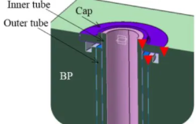
According to previous specification, in order to increase blanket reliability and availability, double welds shall be foreseen between water and Pb-Li and between water and plasma [26]. This will concern, in particular, welds of DWTs on the blanket module back plate. According to present manufacturing scenario, DWTs will be inserted from the rear into the box (FW plus SWs plus caps), then BP will be inserted and welded to the box and to the DWTs, which means one side access (from outside) for these welds. A configuration for double weld between water and Pb-Li compatible with one side access
requirement, is proposed as schematically shown in Figure 12.
Figure 12: Scheme of the DWT to BP welding
This configuration features three welds (red triangles in the Figure 12) for each tube: the outer tube is at first welded to the back plate, then a "cap" is inserted around the tube, which is then welded to the inner tube and to the BP. The cap thickness has been dimensioned in order to resist to water pressure (15.5 MPa).
GTAW and laser processes could be pertinent, both featuring some advantages and drawbacks. GTAW process is widely used in nuclear environment because of recognized welds quality. It is indeed used for tubes to plate welding, e.g. in steam generators, and off-the-shelf welding heads seem to be available equipped for tube expansion plus orbital welding. Laser welding is advantageous mainly because of smaller welds and induced deformations and because the laser head can be deported from the joint.
The feasibility of such a configuration and the pertinence of the welding process is being assessed through different types of mock ups with an increasing representativeness as described in section 3.2.1. Laboratory Mock Ups (LMU-1), featuring only one tube are used at first to define preliminary WPS. Grade 91 has been used as a material and DWTs have been simulated through a massive tube machined, on one extremity, to represent the inner tube only. Several parameters have been tested, varying chamfers geometry and welding parameters. Pictures of obtained joints are shown in Figure 13. Satisfying results (no defects) have been achieved for GTAW process, while WPS needs to be improved for laser process. Some porosities are indeed observed whose origin and improvement are being investigated. Laboratory Mock Ups 2 (LMU-2), featuring four tubes will be used to assess the effect of one tube welding on the adjacent ones, namely the heat pumping and deformation effect. Intermediate Mock Ups (IMU) featuring more bent tubes (section 3.4.1), will eventually be used to investigate the transferability to a more complex geometry.
It can be seen that HAZ and WZ are, as expected, larger for GTAW process than for laser. Experimental campaign to further optimize geometries and welding parameters for both processes, comprising thermal treatment and mechanical characterization is ongoing.
7/10
(a)
(a) (b)
Figure 13: LMU-1, (a) assembly 4 (TIG), (b) assembly 1903-10-107-6 (laser)
4
Characterization of components
4.1.1 Corrosion of DWTs and welded jointsSeveral EUROFER specimen representative of DWTs (sandwich mock ups) and welds have been manufactured to assess the corrosion resistance of DWTs interface layer and weld regions under irradiation. Plate mock ups (with and without HIP) and row tube corrosion mock ups (without any weld) will also be tested for comparison. While tube mock ups feature the same original metallurgical state, plate and sandwich mock ups differ in their metallurgical state and interface layer chemical composition. Specimen details are summarized in Table 1.
Table 1: details of specimens to be exposed in RVS-3
For each type of mock ups, one mockup will be kept as reference for comparison and at least two will be exposed to the same conditions (corrosion only or corrosion plus irradiation). The impact of manufacturing process (and therefore surface status) will be assessed, as well as the effect of HIP treatment and welding. The microstructural evolutions of candidate materials irradiated in the in-pile water corrosion loop RVS-3 in the LVR-15 research reactor of CVR, simulating PWR operation conditions of the WCLL blanket cooling system will be characterized. The operating conditions of the RVS-3 loop are: pressure of 15.7 MPa, max. temperature of 350 °C, water flow of 1.5-2.0 m/s, and neutron flux of 1×10¹⁸ n/m2·s. The outcome of the research work emphasis on (i) evaluating resistance of DWT candidate materials in simulated operational conditions of the WCLL blanket cooling system and (ii) understanding the knowledge on materials microstructural behaviour exposed to water corrosion environment (hot pressurized water) and neutron flux. The Post-irradiation Test Evaluation (PTE) will be performed in CVR hot-cells with various length scale
analysis techniques that are capable of performing precise post irradiation microstructural examination. Table 2 describes the PTE sequence, techniques and specific aim of characterization. In the current study, it is possible to determine the quantitative changes in the specimens tested in the corrosion loop and evaluate their resistance to exposed test conditions. Primary focus is to characterize oxide layer, microstructure (grain size, texture and precipitates), quantitative chemical analysis as well as hardness to determine the corrosion and irradiation induced material changes.
Table 2: post-irradiation Test Evaluation sequence
4.1.2 Blanket Back Supporting Structure
experimental investigation
The coolant distribution along a BB segment plays a relevant role on the reliable operation of the various breeding blanket modules. Since these modules are cooled in parallel, it is essential to ensure that the flow rates through these modules stay within the operating range. To investigate these aspects, various experiments in the existing facilities are foreseen. Thus, sub-size mock-ups of the HCPB and HCLL Back Supporting Structure (BSS) have been designed at PoliTO [27]. Such mock-ups will be manufactured and tested in the HELOKA experimental facility at KIT [23]. Such experimental campaign will provide useful data in order to validate the models that are used to design the BSS itself, including both detailed (e.g. 3D CFD) and system level (e.g. GETTHEM [28]) models. The mock-ups have been dimensioned as scaled-down version of the full-size BSS, keeping constant the dimensionless parameters relevant for the hydraulic behavior of the coolant inside the manifolds, i.e. the Reynolds number in the main manifold branch and the ratio between main branch and derivation flow areas. The hydraulic similarity has then been checked through CFD analyses (as reported in Figure 14). To complete the experimental setup, a valve system has been dimensioned, aiming at representing the BB modules when connected in between the inlet and outlet manifolds. The valve have been chosen (among off-the-shelf available valves) in order to allow reproducing different operating points (such as cold operation and hot operation), without substituting them.
Figure 14: Comparison of the pseudo-dimensionless pressure drop distributions computed with the 1D and the 3D models in the Inlet Manifold, for the mock-up (dashed, 1D and dotted, 3D)
and full-size (solid, 3D) BSS, respectively (adapted from [27]).
5
Conclusions and further development
This paper summarises activities carried out in Europe in the frame of breeding blanket project manufacturing tasks in the period 2013-2018.
Results of Eurofer weldability assessment are reported with regard to different envisaged welding process. Tests reveal a low sensitivity to cold cracking, both for GTAW and laser processes. A filler wire for the welding of EUROFER steel, with low activation, is developed and manufactured and will soon be evaluated in representative conditions.
In the frame of EU TBMs programme, several techniques are developed, which could be adapted, transferred and consolidated to DEMO BB. In some cases, nonetheless, these techniques are not applicable to DEMO; moreover due to more flexible time-schedule and allocated resources, some alternative, advanced and promising techniques and processes can be envisaged for DEMO whose nowadays maturity level is not compatible with their use in ITER (e.g. additive manufacturing). In this frame, high energy density processes are evaluated in EU DEMO manufacturing programme. This has led to the development and validation of a welding laser head featuring a low geometrical constraint for the welding of medium thickness and the assessment of electron beam potentials for hybrid assembly of components having channels made by additive manufacturing and machining method. An alternative technique Electrical Discharge Machining plus forming has also been investigated for FW manufacturing; a mock-up with a total length of 1600 mm and 12 channels has been manufactured and acceptance tests are almost completed.
More advanced techniques, as PBF laser additive manufacturing process are also evaluated. Results reveal their capability to manufacture components of complex geometries with channels of small dimensions and good mechanical properties compared to those on base material. The robustness of the process for big components manufacturing as well as the behavior of additive manufactured structures under irradiation should be investigated.
The manufacturability of W FW coating is assessed. Good results are obtained by using the VPS technique. Next steps will consist to test of such a coating under relevant surface heat fluxes and relevant temperature gradients via the HELOKA facility.
The manufacturing of DWTs for WCLL, is ongoing with the choice of layer material and deposition technology and the pursue of assembling and bending processes assessment. Promising results have been obtained on grade 91 steel which have to be confirmed on EUROFER. Double welds between DWT and back plate have been designed and assessed using different welding processes. Several EUROFER specimen representative of DWTs and welds have been manufactured to assess the corrosion resistance of DWTs interface layer and weld regions under irradiation. Tests will be performed in the CVR RVS-3 loop and the Post-irradiation Test Evaluation (PTE), performed in CVR hot-cells.
Manufacturing activities for DEMO programme next phase will consist of consolidating ongoing and addressing new issues (mainly linked to big components). These activities can be distinguished in two categories, generic and concept specific. Among generic issues to be further investigated we can highlight:
Assess the capability on industrial scale to machine and more generally to manufacture complex and big (sub-components respecting admissible tolerance. This concern, e.g. the manufacturing of BSS (about 13 m in developed length).
To assess W coatings technologies on larger surface areas.
To consolidate manufacturing technologies (e.g. WPS) defined on small LMUs on more representative mock ups/components.
To assess stress Relief Cracking (reheat cracking) after manufacturing.
To assess the impact of manufacturing steps (comprising heat treatments) on distortion. Numerical simulation can be used to optimize experimental campaign up to full scale mock ups;
To define optimum PWHT and assess the effect of cumulated PWHT on the structure. The aim is to define the range of satisfying metallurgical and mechanical requirements.
To assess mechanical properties of welded joint for their qualification with regard to design and fabrication codes and standard.
To assess and to develop Non-destructive Tests on representative component including low accessibility and channel environment. Tests should be done in accordance with regulation and code requirements.
To investigate promising alternative manufacturing technology and to develop the associated preliminary procedure (task strongly linked to the evolution of design).
To supply plate, bar and tube EUROFER material. In addition to that, more “concept specific” issues needs to be further investigated, e.g. with regard to the WCLL concept, the assembly and characterization of tube bundles, its assembly with BP, manufacturing of a functional mock-up DWT+Plates to be tested and characterization (mechanical, thermo-mechanical, corrosion).
Acknowledgments
This work has been carried out within the framework of the EUROfusion Consortium and has received funding
9/10
from the Euratom research and training programme 2014-2018 under grant agreement No 633053. The views and opinions expressed herein do not necessarily reflect those of the European Commission.
References
[1] C. Bachmann and al., "Initial DEMO Tokamak Design Configuration Studies," Fusion Engineering
and Design, Vols. 98-99, pp. 1423-1426, 2015.
[2] F. Romanelli, "Roadmap to the Realization of Fusion Energy".
[3] F. Tavassoli, "EUROFER Steel, Development to Full Code Qualification," 6th International Conference
on Creep, Fatigue and Creep-Fatigue Interaction [CF-6], pp. 300-308, 2013.
[4] F. Tavassoli, A. Alamo, L. Bedel, L. Forest, J.-M. Gentzbittel and al., "Materials design data for reduced activation martensitic steel type EUROFER," Journal of Nuclear Materials, pp. 257-262, 2004.
[5] M. Zmitko and al., "The European ITER Test Blanket Modules: Current status of fabrication technologies development and a way forward,"
Fusion Engineering and Design, pp. 199-207, 2015.
[6] O. Doyen and al., "Assessment of HCLL-TBM optimum welding sequence scenario to minimize welding distortions," Fusion Engineering and
Design, vol. 121, pp. 80-86, 2017.
[7] L. Forest and al., "The European ITER Test Blanket Modules: Fabrication R&D progress for HCLL and HCPB," Fusion Engineering and Design, p. In press, 2018.
[8] M. Zmitko and al., "The European ITER Test Blanket Modules: EUROFER97 material and TBM’s fabrication technologies development and qualification," Fusion Engineering and Design, vol. 124, pp. 767-773, 2017.
[9] W. F. Newell, "Guideline for Welding P(T) 91," Euroweld Ltd, 2001.
[10] D. Richardot and al., "The T92/P92 Book," Vallourec & Mannesmann Tubes, 2000.
[11] Standard, "17642-2, NF EN ISO, Destructive tests on welds in metallic materials - cold cracking tests for weldments - Arc welding processes - Part 2: Self-restraint tests," July 2005.
[12] Standard, "1011-2, NF EN, Welding / recommendations for welding of metallic materials / Part 2: Arc welding of ferritic steels," July 2002. [13] Standard, "17844, FD CEN ISO/TR, Welding /
Comparison of standardised methods for the avoidance of cold cracks," February 2005.
[14] Standard, "3690, NF EN ISO, Welding and allied processes - Determination of hydrogen content in arc weld metal," June 2012.
[15] A. Fontes, "FUSION TECHNOLOGY / Annual Report of the association EURATOM-CEA 2001 / RAFM steels - Qualification fabrication processes
EUROFER weldability," 2001.
[16] L. Forest, "FUSION TECHNOLOGY / Annual Report of the association EURATOM-CEA 2002 / RAFM steels - Tensile and impact test on EUROFER weldments," 2002.
[17] AFCEN, "RCC-MRx - Design and construction rules for mechanical components of nuclear installations applicable to high temperature structures and to the ITER vacuum vessel," 2015.
[18] D. Qu, W. Basuki and J. Aktaa, "Numerical assessment of functionally graded tungsten/EUROFER coating system for first wall applications," Fusion Eng. Des., Vols. 98-99, pp. 1389-1393, 2015.
[19] D. Qu, W. Basuki, J. Gibmeier, R. Vaßen and J. Aktaa, "Development of Functionally Graded Tungsten/EUROFER Coating System for First Wall Application," Fusion Sci. Technol., vol. 3, pp. 578-581, 2015.
[20] D. Qu., Development of functionally graded
tungsten/EUROFER coating systems, Karlsruhe,
2016.
[21] J. Aktaa and D. Qu, "Spraying 2 mm thick coating system and optimising the spray parameters," EUROfusion IDM EFDA_D_2MLW4C, 2016. [22] T. Emmerich and J. Aktaa, "Report on coating and
testing of a FW Mock-up with W-sacrificial coating and W/EUROFER functional," EUROfusion IDM EFDA_D_2N9CUB, 2017.
[23] B. Ghidersa, M. Ionescu-Bujor and G. Janeschitz, "Helium Loop Karlsruhe (HELOKA): A valuable tool for testing and qualifying ITER components and their He cooling circuits," Fusion Engineering and
Design, vol. 81, no. 8-14, pp. 1471-1476, 2006.
[24] M. Eid, L. Giancarli and E. Proust, "Evaluation of different options of cooling tube design for the Water Cooled Pb-17Li Breeder DEMO Blanket. A preliminary reliability analysis," CEA Report, SERMA/BP/1627, 1994.
[25] M. Eid and A. Li Puma, "Double walled tube concept impact on the pressure tubes reliability/availability," CEA Report, SERMA/LCA/RT/01-2999/A, 2001.
[26] L. Giancarli and M. Fütterer, "Water Cooled Pb-17Li Blanket Line Status report on EU related activities," CEA Report, SERMA/LCA/1801, 1995.
[27] A. Bertinetti, A. Froio, B.-E. Ghidersa, F. A. Hernández González, L. Savoldi and R. Zanino, "Hydraulic Modeling of a Segment of the EU DEMO HCPB Breeding Blanket Back Supporting Structure," Fusion Engineering and Design, vol. http://dx.doi.irg/10.1016/j.fusengdes.2018.04.099, 2018 (in press).
[28] A. Froio, F. Cismondi, L. Savoldi and R. Zanino, "Thermal-hydraulic analysis of the EU DEMO Helium-Cooled Pebble Bed Breeding Blanket using the GETTHEM code," IEEE Transactions on