HAL Id: cea-02328960
https://hal-cea.archives-ouvertes.fr/cea-02328960
Submitted on 4 Dec 2019HAL is a multi-disciplinary open access
archive for the deposit and dissemination of sci-entific research documents, whether they are pub-lished or not. The documents may come from teaching and research institutions in France or abroad, or from public or private research centers.
L’archive ouverte pluridisciplinaire HAL, est destinée au dépôt et à la diffusion de documents scientifiques de niveau recherche, publiés ou non, émanant des établissements d’enseignement et de recherche français ou étrangers, des laboratoires publics ou privés.
Hydrodynamic numerical simulations of a prototypical
oxide-metal corium melt representative of fukushima
1-F1 severe accident conditions
A. Boulin, J.F. Haquet, P. Piluso, M. Semenov, M. Antoni, T. Washiya, A.
Nakayoshi, T. Kitagaki
To cite this version:
A. Boulin, J.F. Haquet, P. Piluso, M. Semenov, M. Antoni, et al.. Hydrodynamic numerical simulations of a prototypical oxide-metal corium melt representative of fukushima 1-F1 severe accident conditions. ATH 2018, Nov 2018, Orlando, United States. �cea-02328960�
HYDRODYNAMIC NUMERICAL SIMULATIONS OF A PROTOTYPICAL
OXIDE-METAL CORIUM MELT REPRESENTATIVE OF FUKUSHIMA
1-F1 SEVERE ACCIDENT CONDITIONS
A. Boulin, J.F. Haquet, P. Piluso CEA-Cadarache,
DEN/DTN/SMTA
13108 Saint-Paul-lez-Durance, France
anne.boulin@cea.fr;jean-francois.haquet@cea.fr; pascal.piluso@cea.fr
S. Semenov, M. Antoni Aix Marseille University
CNRS, MADIREL
141 Trav. Charles Susini,13102 Marseille, France
s.semenov@univ-amu.fr; m.antoni@univ-amu.fr T. Washiya, A. Nakayoshi, T. Kitagaki
Japan Atomic Energy Agency
Collaborative Laboratories for Advanced Decommissioning Science 4-33 Muramatsu, Tokai-mura, Ibaraki, 319-1194 Japan
washiya.tadahiro@jaea.go.jp; nakayoshi.akira@jaea.go.jp; kitagaki.toru@jaea.go.jp
ABSTRACT
In the frame of Severe Accident studies, the VULCANO-facility at PLINIUS-platform (CEA - Cadarache) is devoted to the understanding of the interaction of corium with a concrete containment pit (Molten Corium Concrete Interaction-MCCI) [1]. The VULCANO VF-U1 experiment was designed to be closer as possible of the MCCI conditions possibly occurring in the Fukushima F1 reactor considering the coexistence of two dispersed phases (metallic liquid droplets and gaseous bubbles) in a continuous phase (oxide melt liquid). A MCCI industrial code was used to perform predictive calculation of the VF-U1 experiment, being closer as possible of Fukushima 1-F1 MCCI conditions. The results shown that the axial ablation is 8 times higher than the radial one. Then, a multiplicative factor of 8 for the axial heat exchange coefficient must be applied to find the final cavity shape. VULCANO VF-U1 Post-Test Analyses have shown that the metallic phase is preferably close to the vertical concrete walls and at the bottom of the test section whereas a stratification due to density difference between the oxide and the metallic phase is expected (as modeling by the MCCI code). Regarding to the real coupling physical effects in the integral the VULCANO-ICB test and the difficulties for the MCCI code to reproduce experimental behaviors, numerical simulations were conducted. For this purpose, a multiphase Volume Of Fluid (VOF) code at AMU (MADIREL) has been developed . In these calculations, the corium has been modelled numerically under isothermal conditions as a two-dimensional dispersed medium with multiple metal drops and gas bubbles. The results showed a possible hydrodynamic re-localization matching to experimental results.
KEYWORDS Molten Corium Concrete Interaction, Fukushima, Volume Of Fluid, multiphasic, stratification
1. INTRODUCTION
In case of a severe accident in a Light Water Reactor, corium, a complex and aggressive mixture including nuclear fuel, cladding and structural materials -so-called corium-, can be formed in the reactor vessel. In some scenarios, corium is assumed to melt through the vessel and spreads over the basemat of the reactor cavity and finally starts to interact with the concrete (Molten Core Concrete Interaction - MCCI). MCCI is a complex process characterized by concrete ablation and volatile generation with some key phenomena which are coupled together: thermal and solutal convection (due to the ablation of the concrete at a lower temperature than the melt one) in a bubble-agitated melt, physico-chemical evolution of the corium pool with a wide solidification range for the oxide melt part (from 3000 K at the beginning of the MCCI to 2000 K at the end of the MCCI process). Due to the specific properties of uranium dioxide, experiments with prototypic materials are absolutely necessary. The MCCI VULCANO program dedicated to MCCI understanding and modelling has been performed in the frame of national and international collaboration (EC-EDF-SUEZ-IRSN-CEA) during these last 10 years [1]. Twelve 2D-experiments have been carried out in the CEA-VULCANO-ICB facility with prototypic corium and sustained heating, simulating different PWRs severe accident conditions.
In 2011, after the earthquake and the tsunami, severe accidents have occurred at Fukushima Dai-chi units BWRs 1-3. From the status of current common knowledge for the Fukushima accidents, it seems that vessel of unit 1-F1 has failed and corium has interacted with concrete. The VF-U1 experiment has been performed in the VULCANO- facility, specially designed to be representative as being the “Best Estimate” MCCI conditions occurring at Fukushima 1-F1 reactor, considering the coexistence of two dispersed phases (metallic liquid droplets and gaseous bubbles) in a continuous phase (oxide melt). Calculations of VF-U1 test were performed using the MCCI code in order to compare calculated and experimental results, especially concerning the ablation direction and final shape of ablated cavity . No segregation due to the density difference between the oxide and the metallic phase has been estimated by MCCI-code, compared to the hydrodynamic segregation experimentally observed in the test section
In order to understand such unexpected behavior, numerical simulations were performed. Under isothermal conditions (temperature of 393 K), the oxide corium has been modelled numerically. For this purpose, a multiphase Volume of Fluid (VOF) code has been developed by AMU (MADIREL) and applied on VULCANO VF-U1 test.
A section of this paper deals with the description of the VF-U1 test, experimental results and its calculation using MCCI code. Another section is dedicated to the numerical simulations and its results before a discussion for the application of the VOF method for MCCI studies.
VULCANO VF-U1 TEST AND MCCI CODE SIMULATION
2.1. VULCANO VF-U1 test description
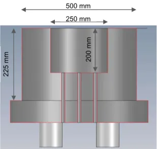
The test section is cylindrical (see Fig. 1). The inner diameter of the test section is 250 mm and its length is 200 mm. The initial thickness of the concrete walls is 125 mm.
The concrete composition is given in Table I. The initial mixture (powder of UO2, ZrO2 and Zr, stainless
steel balls – Fe, Ni, Cr- , and plates of ZrO2) weight is 46.4 kg.
An induction generator is used for both melting and sustained heating of the corium. After melting, 42,9 kg of corium are produced (3.5 kg are ejected). Its composition is given in Table II.
Figure 1. Overview of VF-U1 test section. Table I. VF-U1 concrete composition (weight %)
Component Al2O3 CaCO3 CaOH2 SiO2 H2O Fe2O3
Weight fraction
(%) 14 7 10 58 5 6
Table II. VF-U1 corium composition (after melting)
Component UO2 ZrO2 CaO SiO2 Zr Fe Cr Ni
Weight fraction (%) 58.8 15.6 0.6 0 11.8 9.5 2.2 1.5 Weight (kg) 25.23 6.69 0.25 0.01 5.06 4.08 0.96 0.62
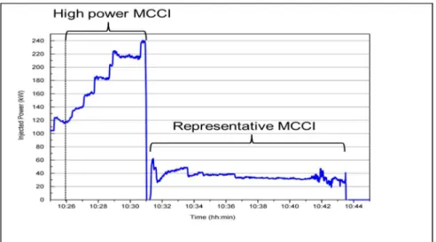
The calculated liquidus temperature of the initial molten melt is about 2750 K. The MCCI has started at (10:25:59) till the stop of power induction system (10:43:30). As illustrated on Fig. 2, after the end of the melting, the injected power grew up from 200 kW to 240 kW. Then, between 10:30:56 and 10:43:29, the injected power, closed to 38 kW is representative of medium and long term of MCCI (heat fluxes about 150 kW/m2 assuming isotropic ablation)
500 mm 250 mm 2 2 5 m m 2 0 0 m m
Figure 2. Injected power into the melt during the MCCI phase of VF-U1 2.2. VULCANO VF-U1 experimental results
The initial and final experimental ablation profiles are shown on Fig. 3. The “best-estimate” final ablation profile is obtained from the TC measurements and dismantling observations. It appears that the axial ablation is six times greater than the radial one (mean axial ablation depth is about 𝑑 = 6 𝑐𝑚 compared to mean radial ablation depth which is 𝑑 = 1.1 𝑐𝑚). The ablated concrete volume during MCCI phases evaluated from these profiles is about 15.3 liters
Figure 3. Initial (dotted black line) and final ablation (red line with dots) profiles of the representative MCCI phase
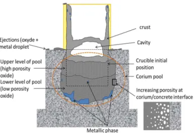
Figure 4. Topology of the frozen melt
The dismantling of the VULCANO VF-U1 test section has shown a specific ablated shape and spatial configuration between the oxide melt and the metallic phase. As illustrated on Fig. 4 and Fig. 5, a continuous metallic phase is observed in the bottom of the cavity and close to the vertical concrete walls.
Figure 5. Topology of metallic alloy 2.3. VF-U1, MCCI code calculations
For some years, a MCCI code has been developed in order to capitalize the understanding and the knowledge of MCCI with different concretes and configurations. In this code, there is no meshing of the corium pool (one single layer -0D- or two layers if stratification).Only main assumptions related to specific VF-U1 calculations are described for this MCCI code.
In case of oxide-metal corium, stratification of immiscible liquid phases might exist according to the BALISE criterion (based on gas flow rate and the density difference which allows stratification if the gas superficial velocity is lower than a limit velocity based on the density difference between an heavy and a light liquid) [2]. In this case, the two layers are considered in thermodynamic equilibrium at the interfacial temperature between the two liquids. Thus, there is no crust between the two liquid layers. In order to take
into account an isotropic ablation, the user can impose a multiplicative coefficient on the heat transfer coefficients.
A first calculation of the VF-U1 test, performed with the physical models proposed by default in this version of the software, allowed to calculate correctly the volume ablated on all the test. Indeed, the calculated ablated volume is 0.85 l which is unless 10 % near the experimental one (0.96 l). It confirmed the injected profile of power deduced from the exploitation of the measurements made during the experiment. Moreover, this calculation correctly reproduced the kinetics of ablation during the first phase (high power MCCI on figure): the profile ablated in the end of this phase was very close to that determined experimentally. The simulation of the second phase required to reproduce the anisotropy by introducing a multiplicative coefficient of 8 on the convective exchanges in lower wall. Up to now, there is no available phenomenology explanation of this anisotropic process of ablation The final shape cavity is well reproduced by the simulation (see Fig. 6).
However, the MCCI code predicted no segregation in this configuration. Furthermore, the level of description of the melt (0D, multi-layers) does not allow neither to report local important information such as zones of the oxide phase (more or less porous), nor to represent the final distribution of the metallic phase (inclusions, tongues in walls). The unexpected location of the metallic phase seems to be a key to understand the specific phenomenology of Fukushima-Daiichi corium-concrete interaction. In order to understand such unexpected behavior, numerical simulations are necessary and have been developed. Under isothermal conditions, the corium has been modelled numerically in the frame of an AMU/CEA agreement. For this purpose, a multiphase volume of fluid (VOF) code developed at AMU (MADIREL) is employed.
Figure 6. : Initial and final ablation profiles calculated with MCCI-Code and comparison to the experimental profile
NUMERICAL SIMULATIONS OF THE HYDRODYNAMIC BEHAVIOR OF A OXIDE-METAL CORIUM IN CASE OF MCCI
3.1. Methodology for three-phase VOF
The corium was modelled numerically under isothermal conditions as a two dimensional dispersed medium with metal drops and gas bubbles. For this purpose, a homemade multiphase volume of fluid (VOF) code is employed ([3],[4]). In VOF methods, different immiscible fluids are treated as a unique continuous phase but with changing material properties according to the local value of color functions.
The Navier-Stokes equation is modified introducing a capillarity force (𝑓⃗ ): 𝜌𝜕𝑉⃗
𝜕𝑡 + 𝜌𝑉⃗. ∇𝑉⃗ = −∇P + μ∆V⃗ + 𝜌𝑔⃗ + 𝑓⃗
A color function Ci(x,y,t) (volumic fraction of the ‘i’ phase at the x,y position) is defined and advected
with an hyperbolic equation :
𝜕𝐶
𝜕𝑡 + 𝑉⃗. ∇𝐶 = 0
with : i=ox (oxidic phase) or i=met (metallic drop) or i=gas (gas bubble) and Cox(x,y,t) + Cmet(x,y,t) + Cgas(x,y,t) = 1
The capillary force is computed from the color function according to Brackbill’s approach [5] :
𝑓⃗ = 𝜎 𝜅 𝑛⃗ 𝛿
Where, 𝛿 = |∇𝐶 |, 𝜅 is the curvature and 𝑛 the normal to the interface and 𝜎 , the phase specific surface tension of the i phase
In case of three phases being in contact, interfacial tensions 𝜎 can be expressed through “artificial” phase specific surface tensions such as 𝜎 = 𝜎 + 𝜎 , (see Fig. 7, [6]). In this case, the following relationships can be obtained:
ox-met +
ox-gas
met-gas)
ox-met
ox-met +
met-gas)
ox-met +
ox-met +
met-gas)(1)
(2)
(3)
(4)
Figure 7. Representation of a three phases contact point. Each phase is represented by a specific color.
Knowing the value of 𝐶 (x,y,t) for each phase allows the final computation of the physical properties using approximation with simple mixing laws (for density and viscosity) :
𝜌 = 𝜌 𝐶 + 𝜌 𝐶 + 𝜌 𝐶 𝜇 = 𝜇 𝐶 + 𝜇 𝐶 + 𝜇 𝐶
Wetting of the walls by the metallic phase are treated numerically (to our knowledge no model available yet in the literature). A contact between the wall and the metallic phase is considered as established only when the near-wall cell is fully filled with the metal color function .If it happens, then, according to the algorithm, the near-wall cell stops flowing: the wall boundary conditions are set on each of its sides. This is equivalent to cell solidification and, though it is purely artificial process, it helps simulating a strong adhesion between the wall and the liquid metallic phase.
The scheme VOF-PLIC (Piecewise Linear Interface Calculation) is used for the interface reconstruction. Color functions are advected using the Eulerian Implicit – Lagrangian Explicite (EI – LE) method [7]The interfacial curvature is computed with the help of a height function [8]. The finite volume method on a staggered uniform computational mesh is used for spatial discretization of all the equations. The resulting system of equations is solved with help of effective penta-diagonal solvers:
- MSIP (Modified Strongly Implicit Procedure) for velocity components
- CG-SIP (Conjugate Gradient with Strongly Implicit Procedure preconditioner) for pressure. 3.2. Physical properties and initial conditions
The physical properties corresponding to early stage of VF-U1 experiment are listed in Table III. Table III. Physical properties used in the numerical simulations
ox
(kg/m3) (kg/mmet3) (kg/mgas3) (kg/(s.m)) ox (kg/(s.m)) met (kg/(s.m)) gas (N/m) ox-gas (N/m) met-gas (N/m) ox-met
6312 6461 0.17 0.0194 4.75 10-3 6.187 10-5 0.58 1.79 0.25
The computational mesh of size 250x150 elements has been used to model 2D physical domain of size 250x150 mm2 (15 cm corresponding to the initial molten corium height).
The initial distribution of metallic drops and gas bubble is imposed as visualized in in Fig. 8. The degassing description and the metallic drop oxidation (due to either dissolved oxygen in the oxide phase
(6) (7)
or air bubble and metal drop contact) are not taken into account. Initial average size of metallic drops is 30 mm (volume fraction of 13%) and the one of gas bubbles is 5 mm (volume fraction of 7,5%)
Figure 8. Initial repartition of the 3 phases used in the numerical simulations (gas bubbles in orange, metal drops in black and the oxidic phase in blue)
3.3 Numerical simulations of a oxide-metal corium percolated by gas bubbles: application to VF-U1 MCCI
As shown in Fig. 9, the phase separation occurring in the presence of a suspension of metallic drops (black color in Fig. 9) in an oxide phase (blue color in Fig. 9) results from two phenomena:
- Convective flow within the melt due to buoyancy force
- Wetting of the concrete walls by the metallic phase (rising gas bubbles near the lateral walls also contribute to the upward motion of the metallic phase and to the appearance of wetting phenomena) For the first 10 seconds VF-U1, the results of numerical simulation are shown at different steps. It is important to stress the following points obtained thanks to the numerical simulations (see fig. 10) - The presence of a continuous metallic phase in contact with the bottom wall at specific zones, - Millimetric metallic droplets floating in the oxide phase,
- Metallic wetting patterns on the right lateral wall.
This final result is in agreement with experimental phenomenology observed for VULCANO VF-U1, allowing for the first time a local insight for the evolution of the melt.
25 cm
15 cm
Figure 9. Time evolution for t ≤ 0,54s for VF-U1 simulation. Black, orange and blue colors represent metal, gas and oxide phase respectively
Figure 10. Snapshots of VF-U1 simulation for 6s < t < 10s.Black, orange and blue colors represent metal, gas and oxide phase respectively
2. CONCLUSIONS
In the frame of severe accidents studies for Fukushima Daiichi 1F1 reactor, an experimental test, VF-U1, has been performed at CEA-Cadarache on the VULCANO facility of the PLINIUS platform with prototypical corium. The coupled phenomena involved in corium-concrete interaction, representative of Fukushima Daiichi conditions have shown another ablation mechanism with an important axial ablation and re-localization of metallic melt on the bottom vertical walls. Some pre and post-test calculation have been performed using a classical industrial MCCI code, allowing finding the ablated concrete volume applying artificially a coefficient rate, but not the configuration of the phases (metallic and oxide phases). For these reasons, it has been decided to develop a VOF code, allowing to have locally a better description of the different coupled phenomena, firstly under isothermal conditions
Thanks to this new approach for MCCI, it has been possible to obtain a satisfactory, though qualitative, spatial phase distribution and to have a dynamic insight of the 3 phases. One can conclude that the numerical
t = 0,4000s t = 0,5400s
Continuous metallic phase wetting with side walls phenomenon
metallic droplets t = 6s
t = 8s
tool allows simulating complex bubble droplet interactions and that the coalescence phenomena are precisely described. The simulation of VF-U1 MCCI over 10 seconds took less than 3 days of computational time on one CPU core
In order to improve the wetting modeling and to simulate the concrete ablation process, it is planned to take into account the concrete walls as a 4-th phase .The inlet of gaseous phase will be modified in order to take into account the degassing description (continuous, intermittent…). Furthermore, the oxidation of the metal phase (due to either dissolved oxygen in the oxide phase or air bubble and metal drop contact) should be implemented. The parallelization of this CFD coder would reduce CPU time required to simulate more than the 10 first secondes.
More generally, in order to update the safety numerical tools, developing new modeling to increase their reliability should be now done taking into account up-scaling from local-scale (DNS or CFD codes) to macroscopic scale (such as MCCI code). This is one of the objective of H2020 proposal called “Ex-Vessel Retention European Simulation Tools EVEREST”,
ACKNOWLEDGMENTS
This work has been partly done in the frame of JAEA-CEA collaboration for a better knowledge on Fukushima-Daiichi Severe Accidents.This paper includes the results obtained under the research program entrusted to the International Research Institute for Nuclear Decommissioning (IRID) by the Agency for Natural Resources and Energy, Ministry of Economy, Trade and Industry (METI) of Japan.
REFERENCES
1. C. Journeau, P. Piluso, J.F. Haquet, E. Boccaccio, V. Saldo, J.M. Bonnet, S. Malaval, L; Carénini, L. Brissoneau, “Two-dimensional interaction of oxidic corium with concretes: The VULCANO VB test series”, Annals of Nuclear Energy, Volume 36, pp. 1597-1610 (2009)
2. B. Spindler, B. Tourniaire, J.M. Seiler, “Simulation of MCCI with the MCCI code based on the phase segregation model”, Nuclear Engineering and Design, Volume 236, pp. 2264-2270 (2006)
3. A. Lekhlifi,J. Ouazzani, M. Antoni, “Drainage of water droplets in a bounded paraffin oil continuous phase : role of temperature, size and boundary walls”, Colloids and surfaces A, Volume 460, pp. 342-350 (2014)
4. A. Lekhlifi,J. Ouazzani, M. Antoni, “A numerical investigation on the drainage of a surfactant-modified water droplet in paraffin oil”, Adv. Colloid Interface Sci., Volume 222, pp. 446-460 (2015)
5. J.U. Brackbill, D.B. Kothe, C. Zemach, “A continuum method for modeling surface tension”, J. Comput. Phys., Volume 100, pp. 335-354 (1992)
6. N. Tofighi, M. Yildiz, “Numerical simulation of single droplet dynamics in three-phase flows using ISPH”, Computers and Mathematics with Applications, Volume 66, pp. 525–536 (2013)
7. E. Aulisa, S. Manservisi, R. Scardovelli, S. Zaleski, “A geometrical area-preserving Volume-of-Fluid advection method”, J. Comput. Phys., Volume 192, pp. 355-364 (2003)
8. S. Popinet, “An accurate adaptive solver for surface-tension-driven interfacial flows”, J. Comput. Phys., Volume 228, pp. 5838-5866 (2009)