Academic and Research Staff
Prof. M. Eden Prof. J. Allen Prof. B. A. Blesser Prof. T. S. Huang Prof. F. F. Lee Prof. S. J. Mason Prof. W. F. Schreiber J. Bonn W. T. Borroz J. E. Bowie B. E. Boyle P. Coueignoux J. R. Ellis, Jr. I. S. Englander A. M. Fakhr A. E. Filip S. G. Finn D. W. HartmanProf. D. E. Troxel
Prof. I. T. Young Dr. R. R. Archer Dr. G. H. Granlund Dr. E. G. Guttmann Dr. K. R. Ingham Graduate Students M. Hubelbank F. H. IvesJ. W. Klovstad
H. S. MagnuskiP. L. Miller
B. Minkow O. R. Mitchell, Jr. J. A. Myers D. O'Shaughnessy R. A. Piankian R. S. Putnam R. San Antonio Dr. J. I. Makhoul Dr. D. M. Ozonoff Dr. O. J. Tretiak F. X. Carroll Deborah A. Finkel E. R. Jensen J. S. Ventura R. J. Shillman D. G. Sitler J. R. Sloan A. A. Smith R. D. Solomon J. H. Stabler W. D. Stratton H-m. D. Toong K. P. Wacks H. M. Wolfson K. H. YungA.
RECOGNITION AND ANAL'
BY COMPUTER
YSIS OF BIOLOGICAL OBJECTS
This report describes the latest applications of the modular picture processing package (MP 3 ) developed in our group. This package was originally prepared by J. E. Green and 0. J. Tretiak, and further developed by J. E. Green. In the past year certain modifications have been made that allow greater flexibility in MP 3 . At present, the package is used for analysis of erythrocytes (red blood cells) both normal and those infected with malarial parasites. Projects are under way to adapt MP 3 to recognize and analyze chromosomes and reticulocytes. The software was written for implementation on a PDP-9 computer with 32K core memory and 106 word disk memory.
Functions performed by this package can be divided into three main categories.
1. Receiving and Storing Digitized Pictures
Each picture is sampled on a rectangular array of points by a mechanism that will be described. The brightness corresponding to each point is stored as a 6-bit number, packed 3 per word in the PDP-9 computer. These brightness values are stored as a one-dimensional array.1 Resolution and size of the picture can be varied as desired. The only factor that limits the resolution is the scanning device and the only factor
This work was supported by the National Institutes of Health (Grant 5 P01 GM14940-06).
limiting the size is the core memory required to store and analyze the picture. For example, on the PDP-9 computer, a picture no larger than 150 columns X 190 rows can be processed.
Two input sources are available to the computer (Fig. XII-1).
FLYING INTERFACE SPOT WITH SCANNER PDP-9 PDP -9 COMPUTER MICROSCOPE SERIAL
TEMPO COMPUTER LINK
Fig. XII-1. Input sources available to the PDP-9 computer.
(a) Flying-Spot Transparency Scanner (System I)
System I is a high-resolution flying-spot scanner designed and built in this labo-ratory.2 This system is not directly linked to the microscope, and for this reason it is necessary to take a photomicrograph of several microscopic fields and scan these photographs on the transparency scanner. The photographic film is Kodak Panatomic X. Exposures are chosen so that the linear region of the dose-response (H-D) curves is used. After scanning the transparency (negative), the total digitized brightness is sent to the computer through an interface.
(b) Microscope and Tempo Computer (System II)
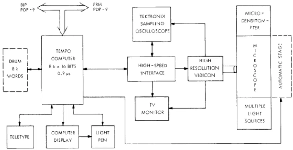
This system employs several different devices to scan pictures directly from a microscopic field. A block diagram of the system is shown in Fig. XII-2. The soft-ware written for implementation on the Tempo computer is capable of scanning the desired microscopic field with a given resolution at the required magnification. A
powerful feature of this system is the capability of the scanner to average each picture column an arbitrary number of times which can be specified by the user. The effect of such averaging is to reduce the noise in the scanning process, if the noise is zero mean and additive.
After each picture is scanned, it can be sent to either of the available PDP-9 com-puters (BIP or FRM). At this point the digitized picture can either be recorded on a Dec-tape and/or analyzed as it is received.
The advantage of System II over the System I is that scanning is done directly and not through recording microscopic fields on a transparency, and hence the time that would be required for photographing and processing each field is saved. Also, there
inaccuracy in photography can be removed. A drawback of this system is that there is a loss in reproducibility, since it is rather difficult to return to scan a given field for the second time after that field has been varied.
BIP FRM PDP-9 PDP-9 <PDP-9 PDP-9 TEKTRONIX MICRO-SAMPLING DENSITOM -OSCILLOSCOPE ETER TEMPO I < DRUM COMPUTHIGH R
S 8 k 8 k x 16 BITS HIGH-SPEED - RESOLUTION
0.9 ps INTERFACE I ON IWORDS VIDICON C TV MULTIPLE MONITOR LIGHT SOURCES COMPUTER LIGHT
TELETYPE DISPLAY PEN
Fig. XII-2. Television- microscope scanning system.
2. Locating Objects in the Picture
Since objects are scanned in a rather uniform background, the brightness of a back-ground point is markedly different from that of an object point. Algorithms have been developed to locate the objects in the picture. First, a brightness histogram of all points in the picture is determined, then by appropriate methods3 thresholds are determined to separate the objects from the background. All cells touching the border
are removed from the picture. A systematic search for a point whose corresponding brightness differs from that of the background brightness then begins. Upon encountering the first such point, a contour of the object to which that point belongs is formed. In this way we separate all of the objects from the background.
3. Analysis of the Objects
Since different objects, such as red blood cells, chromosomes, and so forth vary in shape and size, MP 3 must be adapted to each class of objects separately. We have used MP 3 to analyze erythrocytes more than for any other kind of cell or object. For this reason, in the rest of this report we shall explain the functions of MP 3 in the anal-ysis of red blood cells.
Initially, after locating a cell, a refinement of the cell is made by finding the bright-ness histogram of the background in the immediate vicinity of the cell and redefining the threshold values. This process provides improved object definition in local regions of the image.3
Now the cell is ready for analysis and we are able to extract some of the character-istics of the cell (called features) by automatic processing. The most important features that we can now obtain are the following.
a. Mass [summed optical density (SOD)] obtained by summing the optical density at each point over all of the points in the picture. Optical density corresponding to the .th i point is defined as I o (O.D.) = In , i It
t
where It is the intensity corresponding to point i, and Io is the background intensity obtained when the local neighborhood of the cell is histogrammed. Furthermore,
S.O.D. = (0.D.) .
all i
b.
Area of the cell is obtained by counting the total number of picture points on and
inside the contour specifying the cell.
c.
Perimeter of the cell is calculated by counting the total number of points on the
contour of the cell.
d. Mass/area is the ratio of the quantity in (a) divided by the quantity in (c). It is a measure of the mass concentration.
e. Perimeter is a measure of the circularity of the cell. 2 '!Area/wr
For a circle it is equal to Tr and for any other geometrical shape it is greater than rr. f. Area of the central pallor (if any) is a feature representing a measure of the size of the central pallor. It is obtained by defining a threshold for the brightness of the
central pallor and dividing it from the rest of the cell for analysis.
g. Area of inclusions measures such features as Howell-Jolly bodies, Cabot rings, malarial parasites, and nucleus residue.4
Feature (a) contains information about the hemoglobin content of red blood cells. In fact, it is possible to show theoretically that the amount of light absorption by the red
cells is linearly proportional to the mean corpuscular hemoglobin (MCH) content of the cells.5 We have conducted a series of experiments using the flying-spot scanner to verify such a relationship. We are now performing the same set of experiments using System II.
A. M. Fakhr References
1. J. E. Green and 0. J. Tretiak, "Modular Picture Processing Package (Mp3),, Quarterly Progress Report No. 94, Research Laboratory of Electronics, M. I. T., July 15, 1969, pp. 261-279.
2. W. F. Schreiber, "The New Scanner" (unpublished Manual, Cognitive Information Processing Group, Research Laboratory of Electronics, M. I. T., Cambridge, Mass.,
1968).
3. J. E. Green, "Computer Erythrocyte Analysis," Proc. IEEE Conference on Feature Extraction and Selection in Pattern Recognition, Argonne, Illinois, 1970.
4. B. S. Leavell and O. A. Thorup, Jr., Fundamentals of Clinical Hematology (W. B. Saunders Company, Philadelphia, Penn,, Zd ed., 1966).
5. E. G. Guttmann, "Mechanization of the Interpretation of Vaginal Smear," Ph.D. Thesis, Department of Electrical Engineering, M. I. T., October 1970.

![[Ni(cyclam)] 2+ and [Ni(R,S-Me6cyclam)] 2+ as Linkers or Counterions In Uranyl–Organic Species with cis-and trans-1,2-Cyclohexanedicarboxylate Ligands](data:image/gif;base64,R0lGODlhAQABAIAAAP///wAAACH5BAEAAAAALAAAAAABAAEAAAICRAEAOw==)