HAL Id: hal-01278693
https://hal.univ-lorraine.fr/hal-01278693
Submitted on 9 Nov 2018
HAL is a multi-disciplinary open access
archive for the deposit and dissemination of
sci-entific research documents, whether they are
pub-lished or not. The documents may come from
teaching and research institutions in France or
abroad, or from public or private research centers.
L’archive ouverte pluridisciplinaire HAL, est
destinée au dépôt et à la diffusion de documents
scientifiques de niveau recherche, publiés ou non,
émanant des établissements d’enseignement et de
recherche français ou étrangers, des laboratoires
publics ou privés.
Ammonia based CO2 capture process using hollow fiber
membrane contactors
Camel Makhloufi, Elsa Lasseuguette, Jean Christophe Remigy, Bouchra
Belaissaoui, Denis Roizard, Eric Favre
To cite this version:
Camel Makhloufi, Elsa Lasseuguette, Jean Christophe Remigy, Bouchra Belaissaoui, Denis Roizard,
et al.. Ammonia based CO2 capture process using hollow fiber membrane contactors. Journal of
Membrane Science, Elsevier, 2014, 455, pp.236-246. �10.1016/j.memsci.2013.12.063�. �hal-01278693�
OATAO is an open access repository that collects the work of Toulouse
researchers and makes it freely available over the web where possible
Any correspondence concerning this service should be sent
to the repository administrator:
[email protected]
This is an author’s version published in:
http://oatao.univ-toulouse.fr/20258
To cite this version:
Makhloufi, Camel and Tournadre-Lasseuguette, Elsa
and
Remigy, Jean-Christophe
and Belaissaoui, Bouchra and Roizard,
Denis and Favre, Eric Ammonia based CO2 capture process using
hollow fiber membrane contactors. (2014) Journal of Membrane
Science, 455. 236-246. ISSN 0376-7388
Ammonia based CO
2
capture process using hollow fiber
membrane contactors
Camel Makhloufi
a, Elsa Lasseuguette
b,c, Jean Christophe Remigy
b,c, Bouchra Belaissaoui
a,
Denis Roizard
a, Eric Favre
a,na
LRGP-CNRS Université de Lorraine 1, rue Grandville, 54001 Nancy, France b
Université de Toulouse, INPT, UPS, Laboratoire de Génie Chimique 4, Allée Emile Monso, 31030 Toulouse, France c
CNRS, Laboratoire de Génie Chimique, 31030 Toulouse, France
a r t i c l e
i n f o
Keywords: Membrane contactors CO2 Absorption Carbon capture NH3a b s t r a c t
Due to its low regeneration energy demands relative to MEA, ammonia is one of the most attractive solvents for post-combustion CO2 capture processes. Nevertheless, additionally to a lower kinetic
constant, a high ammonia slip takes place when the absorption process is performed in a packed column. In this study, the feasibility of an ammonia based CO2capture process using hollow fiber
membrane contactors is investigated. CO2absorption experiments in ammonia have been performed
with porous polypropylene membranes (Oxyphan) and with two different dense skin composite hollow fibers: tailor made (Teflon AF2400) and commercial (TPX). It is shown that microporous membranes do not offer stable performances, due to salt precipitation and pore blocking. Contrarily however, dense skin membranes show stable and attracting performances, whatever the operating conditions: reduced ammonia slip and intensified CO2 mass transfer are obtained compared to packed column.
The potentialities of dense skin membrane contactors, particularly based on fluorinated polymers, are discussed with regard to both increased CO2mass transfer performances and mitigation of ammonia
volatilization compared to conventional gas/liquid contactors.
1. Introduction
Climate change, which is closely related to anthropogenic CO2
emissions, is one of the main growing issues our society has to face. Particularly, electricity production, mostly performed using fossil fuels, is the largest stationary source. Beyond promoting renewable energies, large efforts have been carried out to reduce CO2emissions through improved power plant efficiencies.
Never-theless, developing technologies able to remove CO2 is still
required in order to achieve the recommended objectives. Coal being the most widespread resource available, post-combustion CO2 capture from coal fired-plant flue gas is of higher interest,
especially for retrofit purpose[1]. Up to now, the most mature technology for post-combustion capture consists in reacting CO2
with a chemical solvent in a packed column. The reference solvent is an extremely reactive primary amine with fast reaction kinetics: monoethanolamine (MEA). Despite extensive research efforts, large scale deployment is not likely to happen. Indeed, energy penalty related to MEA based CO2 capture process in packed
column is prohibitive consequently to the high regeneration energy demand induced by this solvent (around 4 GJ per ton
of CO2removed)[2]. Besides, MEA is corrosive and is subjected to
thermal and oxidative degradation by O2 and SO2. As a result,
volatile pollutants are produced and significant MEA losses take place (up to 6.5 kg MEA per ton CO2) [3]. Accordingly, an
important solvent make up increasing the operational cost and a deep desulfurization of the flue gas (content less than 5 ppm) are compulsory[4].
For these reasons, numerous studies investigate new absorp-tion solvents for post-combusabsorp-tion CO2 capture and, over time,
ammonia in aqueous solution has appeared as a serious candidate for that purpose [5]. Firstly, NH3 could significantly reduce the
energy regeneration demands and save up to 75% energy com-pared to MEA. In addition, NH3is cheaper than MEA (ratio 1/6 on
the same mass basis) and its absorption capacity is 3 times higher. Finally, NH3is not corrosive and does not suffer from thermal or
oxidative degradation. On the contrary, reusable products can be formed when reacting with NOx and SOx and a combined capture of these pollutants can be introduced. Nevertheless, ammonia shows two main drawbacks that lower its interest. First of all, ammonia absorption kinetics is less favorable than MEA, leading thus to larger absorber which increases the investment cost. Then, being highly volatile, high ammonia losses are generally observed when the absorption is performed in direct gas/liquid units such as packed columns. A washing section is therefore required to meet the ammonia emissions limits, thereby increasing again the http://doi.org/10.1016/j.memsci.2013.12.063
n
Corresponding author. Tel.: þ 33 383 17 53 90. E-mail address:[email protected](E. Favre).
operating costs. Additionally, a solvent make-up must be consid-ered. In that context, a gas/liquid contactor offering both improved CO2mass transfer performances and mitigating the ammonia slip
compared to packed column could be of major interest.
Initially tested for CO2absorption by NaOH using microporous
hollow fibers[6,7], membrane contactors are now considered as one of the most promising intensification strategies[8]. Generally speaking, hollow fiber membrane contactors could logically be of interest as gas/liquid units for the absorption of CO2in ammonia
solution. Indeed, the very large interfacial area developed by membrane contactors (up to 6000 m2/m3) compared to packed
columns (around 300 m2/m3
) could potentially result in a signifi-cant improvement of the CO2 absorption capacity compared to
conventional absorption processes [9]. Furthermore, ammonia losses due its high volatility being certainly worsened by a direct contact between gas and liquid, the indirect gas/liquid contact allowed by membrane contactors could possibly lead, at first glance, to ammonia slip mitigation. To our knowledge, no study discussing the feasibility of a process using hollow fiber membrane contactors for CO2 absorption in ammonia has been reported up
to now.
A large number of studies dealing with CO2 absorption by
membrane contactors involve hydrophobic microporous hollow fibers for which impressive intensification factors have been reported[10,11]. Nevertheless, membrane wetting usually takes place after long term use decreasing thus the overall mass transfer coefficient [12]. While many studies have shown that the long term use of MEA for CO2 absorption results in the membrane
wetting for several membrane materials, no study discusses the use of microporous hollow fiber for CO2absorption in ammonia. In
this work, the potential of microporous hollow fibers as gas/liquid contactor for an ammonia based CO2absorption process will be
evaluated and discussed.
To avoid membrane wetting, the reference alternative consists in using composite hollow fibers membrane contactor where a thin dense layer added to a microporous support acts as a physical barrier facing the liquid phase [13,14]. In that case, wetting is suppressed while mass transport performances can be found comparable to those observed in microporous membrane contac-tors[15] in the peculiar case where the dense skin is properly
chosen. Composite hollow fiber membrane contactors as gas liquid contactors for ammonia based CO2 capture process could be of
interest compared to conventional CO2 absorption in a packed
column. Indeed, a chemically resistant composite fiber made of a thin dense layer ideally highly permeable to CO2but less
perme-able to NH3 could potentially lead to a high CO2 mass transfer
intensification while drastically lowering ammonia slip.
In the following, the feasibility, advantages and drawbacks of both conventional microporous and composite hollow fibers for the absorption of CO2in ammonia will be discussed on the basis of
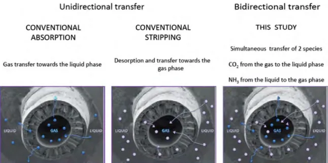
experimental work performed using different lab scale modules. Numerous publications have been already reported for mem-brane contactors fundamental studies and applications [16,17]. Generally speaking, the transfer of a single species is system-atically studied, either in an absorption or in a stripping config-uration (Fig. 1). The study detailed in this paper is however unique in that the simultaneous transfer of two different reacting com-pounds (CO2 and NH3) in two opposite directions is considered
(Fig. 1c). The system is further complicated by the role of water and the possibility to generate precipitating solids through the reaction between CO2, NH3and H2O. As a consequence, solid salt
formation as well as ammonia causticity should absolutely be taken into account for fiber selection.
The objectives of the study are the following:
1. Evaluate the possibilities and limitations of membrane con-tactors based on microporous membranes for CO2absorption in
ammonia.
2. Achieve dense materials screening tests, in order to identify the most appropriate dense skin polymer for CO2 absorption in
ammonia, with an emphasis on chemical resistance and pre-cipitating salt complications.
3. Design dense skin composite hollow fiber membrane contac-tors based on the polymer proposed in step 2, and achieve absorption tests at laboratory scale, with an analysis of the effect of different operating conditions on process performances.
4. Determine the mass transfer characteristics of the different membrane contactors and perform a performances comparison with conventional packed columns.
Fig. 1. Different types of situations investigated for gas–liquid membrane contactors applications. Studies almost systematically address a single solute absorption (a) or stripping (b) operation. In this study, the simultaneous CO2absorption and NH3stripping is considered (c).
2. Mass transfer in hollow fiber membrane contactors Membrane contactors are a promising alternative to packed column, especially in absorption processes accompanied with a fast reaction where the interfacial area should be favored relatively to the reactor volume[18]. Nevertheless, the membrane induces a supplementary mass transfer resistance compared to direct gas/ liquid contactors and the overall CO2mass transfer coefficient KCO2
from the flue gas to the absorbing solution is generally lowered. The membrane resistance is particularly important in the case of composite materials where a dense layer, generally placed at the outer surface of a microporous support, is used as a physical separation between flue gases and absorbing medium. To compete with conventional CO2absorption processes using direct gas/liquid
contactor, the microporous or composite fibers used should allow a high CO2 mass transfer from the flue gas to the ammonia
solution. At the same time, NH3transfer from the solution to the
gas phase should be as low as possible.
To better understand the respective transport of CO2and NH3
and design the most appropriate membrane contactor, a detailed analysis of the overall mass transfer coefficient for each type of system is needed.
2.1. Overall mass transfer coefficient KCO2and KNH3
The CO2and NH3overall mass transfer coefficient respectively
from the gas phase to the absorption liquid (KCO2) and from the
ammonia solution to the gas phase (KNH3) can be described using
the in resistance-in-series model (Fig. 2). The global resistance for each species corresponds to the sum of the resistances induced by the gas, membrane and liquid phase[19]. In the case where the flue gas is circulated in the fibers lumen, the overall mass transfer coefficients KCO2 and KNH3 can be linked to the individual mass
transfer coefficients using the following expressions[16,20,21]: 1 KCO2 ¼do di 1 kg þdo dlm 1 kmCO2 þHCO2 RT 1 EkL ð1Þ 1 KNH3 ¼do di 1 kgþ do dlm 1 kmNH3þ HNH3 RT 1 kL ð2Þ
where do, di and dlm are respectively the outer, inner and
logarithmic mean diameter of the composite fiber (expressed in m). kg and kl are the individual gas and liquid mass transfer
coefficient related to CO2and NH3(m s% 1). kmCO2 and kmNH3are the
membrane mass transfer coefficients of CO2and NH3through the
membrane (m s% 1). E is the enhancement factor due to the
chemical reaction of CO2with ammonia within the liquid phase.
HCO2 and HNH3 are the Henry constant related to CO2 and NH3
(Pa m3mol% 1). NH
3 under its free form being in equilibrium
within the solution with NH4þ ions, HNH3 is considered as a
function of the solution pH. This should reflect the evolution of the free ammonia species concentration as a function of the absorption reaction.
A high KCO2=KNH3ratio is expected, due to the chemical reaction
enhancement term. Increasing KCO2 to enhance the CO2 mass
transfer and simultaneously lowering KNH3 to mitigate ammonia
volatilization would be of major interest, but this requires one to carefully design the membrane mass transfer properties through optimizing the specific mass transfer resistance for each species. This possibility is discussed afterwards.
2.2. Membrane mass transfer coefficient km
2.2.1. Microporous membrane mass transfer coefficient
The transport of a gaseous penetrant through a microporous membrane is defined by the microporous membrane mass transfer
coefficient kmicrogiven by the following relationship[16]:
kmicro¼
Dgasε
τemicro
ð3Þ
kmicrois primarily a function of the material thickness (emicro) and
structural properties, namely porosity ε, tortuosityτ and pore radius. In addition, it depends on the gas diffusivity within the pores (Dgas) and particularly on the ratio between the mean pore
radius rpand the molecular mean free path which defines the
penetrant mass transfer mechanism (mainly molecular diffusion or Knudsen). In order to maximize the gas diffusivity through the microporous structure during CO2 absorption operation,
non-wetted mode is necessary (i.e. with the porous network filled with gas).
Reaching high CO2mass transfer performances using a
micro-porous membrane involves selecting a membrane as thin as possible and showing both a high porosity with large mean pore radius and low tortuosity. Nevertheless, these features necessarily maximize at the same time the ammonia slip from the liquid to the gas phase, because the CO2 and NH3diffusion coefficients in
gaseous phase are very close[19].
2.2.2. Composite membrane mass transfer coefficient and transport through the dense layer
In the case of a composite membrane (Fig. 2), the overall membrane resistance is the sum of the resistances due to the microporous support and the dense layer[15]:
1 km ¼ 1 kmmicro þ 1 kmdense ð4Þ
kmdensecan be determined precisely if the mass transport
proper-ties of the different species are known. Indeed, each species is transferred through the dense layer through a solution diffusion mechanism[22]. As a consequence, the process is fully determined by:
&
A thermodynamic factor which corresponds to the solubility in the polymer S (mol m% 3Pa% 1
)
&
A kinetic factor which corresponds to the species diffusion coefficient in the dense polymer D (m2s% 1).These two contributions are gathered together in a term generally used to characterize the transport of a given species through a dense polymer: the permeability coefficient P (mol m m% 2s% 1Pa% 1). As a consequence, the dense layer mass
transfer coefficient can be obtained through[15]
kmdense¼
PRT edense
ð5Þ
with edensethe dense skin thickness (m) and P the permeability
coefficient related to CO2 or NH3 through the considered
dense skin.
It should be stressed that, whereas microporous membranes only offer a limited number of degrees of freedom for differentiat-ing CO2and NH3mass transfer, a meticulous selection of the dense
skin could potentially allow maximizing CO2mass transfer while
lowering ammonia slip. This target requires designing a composite hollow fiber membrane contactor made of a chemically resistant dense layer showing both[23]:
&
a CO2permeability as high as possible,&
a NH3permeability as low as possible,The possibilities and limitations with respect to this selective mass transfer tuning property are some of the key targets of this study.
3. Materials and methods 3.1. Polymeric films
TPXs
flat sheets were purchased from Goodfellow Cambridge Limiteds
. PDMS was obtained from Perouse Plastie. All samples were used as received. Flat membranes of the copolymers poly (2,2-bis(trifluoromethyl)-4,5-difluoro-1,3dioxole-co-tetrafluor-oethylene) (Teflon AF2400s
, Dupont) were prepared by solution casting from polymers pellets. Homogeneous Teflon AF2400s
films were prepared by casting a 1 wt% solution, previously filtered to 0.45 mm, onto glass dishes in Fluorinert FC-72 (3 M) fluids. After a slow and controlled evaporation of the solvent, the membranes were dried under vacuum at a temperature below the glass transition temperature until constant weight was reached.
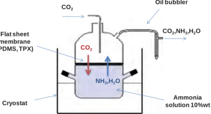
3.2. Permeability measurements and chemical resistance assessment Preliminary absorption experiments were performed using laboratory made flat sheet membranes. The experimental setup (Fig. 3) consists in two compartments separated by a flat sheet. A stagnant fresh ammonia solution of a given concentration is placed in the bottom part of the apparatus while pure CO2flows in
the upper part of the setup. The whole setup is disposed within a cryostat in order to precisely control the temperature. Each experiment was performed using a 10 wt% ammonia solution for a single value of the CO2 volumetric flow. A rubbery amorphous
polymer (polydimethylsiloxane) as well as a glassy material (TPX) were tested in order to stress their ability to chemically withstand the harsh conditions met during the CO2 absorption process in
ammonia. Their physical aspect as well as the amount of ammo-nium salt absorbed has to be taken into account in the material selection process.
Besides chemical resistance tests, CO2 and NH3 permeability
measurements were performed using the Time Lag method[24]. The upstream and downstream pressure gauges are MKS Baratron, respectively, 870B 0–7 bar and 626B 0–26 mbar. The set up is thermostated and each experiment is performed at 294 K. The tests were repeated on a given membrane until at least 5 experi-ments showing results within an average error of 5% were obtained for the set of conditions tested. After permeation tests were performed using CO2 and NH3, any alteration of the
mem-brane performance was verified by performing reference time lag experiments. Any variation of the transport parameter higher than the average error led to a withdrawal of the polymer sample. Care was taken to neutralize all ammonia effluents in sulfuric acid solutions. CO2 Cryostat Oil bubbler CO2,NH3,H2O Flat sheet membrane (PDMS, TPX) Ammonia solution 10%wt CO2 NH3,H2O
3.3. Hollow fibers preparation
Two different types of hollow fiber membrane contactors were designed for this study: microporous membrane contactors and composite membrane contactors. The microporous membrane contactors are made of commercial polypropylene hollow fibers (Oxyphan). Additionally, two other contactors, made of dense skin composite hollow fibers, were prepared: one tailor made obtained by coating a Teflon AF2400 solution on the outer surface of an Oxyphan fiber used as microporous support[15], and a commer-cial hollow fiber (Oxyplus, Membrana) made of a thin layer of poly (4-methyl-1-pentene) coated on the external surface of a poly-propylene microporous support. In each case, the fibers used have been gathered together in the form of a module of 54 fibers for gas/liquid absorption test. Fibers and module characteristics are summarized inTable 1.
3.4. Gas/liquid absorption setup
The experimental setup used for the absorption experiments is shown inFig. 4. A gas mixture made of CO2and N2(15/85 vol) is
produced by means of 2 mass flow controllers (Bronckorst El-Flow Select) and flows through the fibers lumen at atmospheric pressure. Besides, a freshly prepared aqueous ammonia solution (1–3–5 wt%) is circulated counter-currently to the gas mixture in the membrane contactor shell side using a peristaltic pump (Watson and Marlow 314D). The membrane contactor is placed in a thermostated chamber and experiments are performed at 21 1C and 45 1C. A 20 m long stainless steel coil is placed in the enclosure upstream to the membrane contactor for a proper control of the gas temperature. Inlet and outlet gas concentrations (CO2, NH3) are measured on line using an infrared analyzer
MGA3000 (Gruter and Marchand). All ammonia effluents, being gaseous or liquid, are neutralized in sulfuric acid solution. To ensure that the ammonia measured in the outlet gas results from ammonia evaporation only, a water wash of the shell side is performed between each experiment. Moreover, an additional nitrogen sweeping line allows one to remove all the ammonia gas remaining both in the fiber lumen and in the analyzer after each experiment. The same membrane conditioning was used for all membrane contactors (microporous and composite). More specifically, membrane contactors were vacuumed prior to each Table 1
Characteristics of the three types of membrane contactors tested in this study.
Oxyphan Oxyphan-Teflon AF 2400 Oxyplus
Nature of the fiber Microporous Composite Composite
Nature of the dense skin – Teflon AF2400 Poly(4-methyl-1-pentene)
Dense skin thickness (lm) – 1.3 0.1
Microporous fiber material Polypropylene Polypropylene Polypropylene
Microporous fiber outer diameter (lm) 380 380 380
Fiber inner diameter (lm) 280 280 200
Fiber number 54 54 54
Liquid flow conditions Shell side Shell side Shell side
experiment in order to begin each test under similar experimental conditions. Care was taken to perform steady state experiments, checked through mass balance calculations. Each experiment performed on one type of membrane contactor was repeated several times on the same module; additionally, at least 2 membrane contactors of the same type were compared under similar operating conditions in order to ensure liable absorption performances.
4. Results and discussion
4.1. Dense skin selection: preliminary screening tests
The main objective of these preliminary materials screening tests, performed with flat sheet membranes, is to evaluate the candidate polymers that withstand the harsh chemical conditions of the system and offer interesting CO2 and NH3 permeabilities.
Among the different materials tested, totally different behaviors were observed during CO2 absorption in ammonia performed,
thanks to the set-up shown inFig. 3. For instance, a large amount of solid ammonium salt is surprisingly observed when a rubbery PDMS matrix is used (Fig. 5a and b). As a consequence of the salt incorporation within this dense polymer, the membrane weight has increased by almost 400% in mass and the material is disfigured, unusable for further experiments. These results show that, with NH3and CO2fluxes occurring in the opposite directions,
the chemical reaction may in some cases occur inside the poly-meric structure. On the contrary, no degradation is observed when a TPX membrane is used (Fig. 5c), suggesting that a rigid glassy polymer might be more appropriate for an ammonia based CO2
capture process.
Taking into accounts these chemical resistance considerations, CO2 and NH3 pure gas permeability measurements were
per-formed in order to better evaluate the mass transfer through the dense layer. Time lag experiments were performed on the rubbery PDMS as well as on different glassy polymers. Particularly, TPX and Teflon AF2400 were chosen as appropriate dense skin materials. CO2and NH3pure gas permeabilities obtained performing time lag
experiments for these three polymers are summarized inTable 2. CO2permeability for PDMS, TPX and Teflon AF materials are in
good agreement with the literature data [25–27]. PDMS is a solubility selective matrix favoring the transport of condensable penetrants. Being a smaller and more condensable molecule than CO2, NH3 permeation is logically faster than CO2 through the
rubbery PDMS structure and a global selectivity αCO2=NH3 lower
than 1 is observed. NH3 solubility in PDMS is high [24]. Its
simultaneous solubilization with CO2 inside the dynamic free
volume network of the rubbery PDMS could potentially explain the in-situ ammonium salt precipitation observed[28]. Based on the results reported above, rubbery polymers reveal to be inap-propriate and have been deliberately ruled out of the dense skin selection process.
TPX is a glassy semi-crystalline polyolefin with medium CO2
permeability. Considering the size sieving properties of this poly-mer, NH3 permeability is logically higher than CO2 leading to
αCO2=NH3lower than 1. On the contrary, a selectivity αCO2=NH3higher
than 1 is surprisingly achieved for the super glassy Teflon AF2400. In this case, the CO2 permeability is enhanced by its increased
solubility in fluorinated polymers whereas NH3 permeability is
lower than expected by the usual correlation. This unexpected result has been previously assigned to a lower solubility ability of ammonia molecules in fluorinated structures [24]. Composite fibers made of a thin Teflon AF2400 layer have already shown CO2 mass transfer coefficient comparable to those observed in
microporous fibers [15]. The decreased ammonia permeability Fig. 5. Examples of flat membrane samples after exposure to ammonia and CO2in
the set-up shown inFig. 3. (a and b) Two different rubbery (PDMS) samples showing in situ salt precipitation and (c) TPX sample.
Table 2
Pure CO2and NH3permeabilities of PDMS, TPX and Teflon AF2400 films obtained by time-lag experiments.
P(Barrer) PDMS TPXs Teflon AF2400s PCO
2 2652 (0.7%) 99 (1.5%) 3127 (0.3%)
PNH3 6552 (0.4%) 188 (2.9%) 1635 (0.6%)
towards Teflon AF2400 offers attractive characteristics to possibly mitigate the NH3slip from the absorption solution. This possibility
will be discussed afterwards.
More generally, the dense skin selection results reported in this section address unsolved issues on the occurrence of an external or internal salt precipitation process. A rigorous analysis of the different experimentally observed behaviors would require the complex framework of diffusion reaction coupling phenomena to be modeled [19,28]. Depending on the relative concentration ratios of CO2, NH3 and H2O (which vary from one membrane to
another depending on solubility) and local temperature (heat being released through the precipitation reaction), the conditions leading to salt precipitation can take place on the liquid side, inside the membrane or in the gaseous phase. We propose here-after a tentative and qualitative data interpretation.
When a microporous materials is used, water, CO2 and NH3
fluxes will be high and no flux tuning effect can be expected from the membrane because of the absence of selectivity. Furthermore, capillary condensation effects are likely to occur in some pores. These characteristics probably favor the attainment of the salt solubility product within the membrane material, leading to in situ precipitation which has been observed with Oxyphan.
When a rubbery dense skin material such as PDMS is used, ammonia solubility is high, while water and CO2 solubilities
remain larger than that in glassy polymers. These conditions may induce salt precipitation within the membrane material, such as that experimentally observed with the PDMS tests.
For glassy dense skin materials, ammonia concentration will be lower (due to the reverse selective behavior) and water and CO2
solubility is lower than in rubbery PDMS. Because no viscous flow takes place in the material (solution–diffusion process), the prob-ability to locally attain the salt solubility product can be expected to be very low. Consequently, salt precipitation does not take place within the membrane, but may occur in the gas or liquid boundaries, where the three species probability contact is maximal.
It is obvious that these qualitative explanations remain hypothetical and should not be taken as generic. More specifically, the membrane thickness is also expected to play a role, because it will modify the fluxes and associated thermal effects.
In the following, CO2 absorption experiments performed on
both microporous and composite hollow fiber membrane contac-tors under steady state conditions are presented and discussed. 4.2. CO2absorption experiments in microporous hollow fiber
membrane contactors
Generally cheaper than composite hollow fiber membrane contactors, microporous hollow fiber membranes are usually considered as the reference system for CO2absorption operations
[10,16]. Accordingly, CO2absorption experiments were performed
on polypropylene microporous hollow fibers in fresh ammonia solutions of different concentrations (1, 3, 5 wt%). Despite numer-ous attempts, the experiments performed have systematically revealed the impossibility to reach steady state conditions during the absorption operation. An example of results is shown inFig. 6; it can be seen that no stable value of the CO2removal efficiency
can be achieved under the set of operating conditions. The CO2
transfer efficiency decreases indeed continuously from the very beginning of the absorption process. Visual observation confirmed that this behavior results from ammonium salt precipitation within the porous structure as well as on the lumen side of the microporous fibers. As a consequence, CO2 absorption
perfor-mances turn out to be erratic and absolutely no reproducibility is observed. This phenomenon could be explained by a too high ammonia slip from the liquid phase to the gas phase where precipitation takes place in the humid environment. Microporous
hollow fibers being clearly inappropriate for this application, composite hollow fiber membrane contactors have been tested in a second step.
4.3. CO2absorption experiments in composite hollow fiber
membrane contactors
Another set of experiments was performed on commercially available contactors made of composite TPX coated PP fibers (Oxyplus) and tailor made fibers with a reverse selective dense skin of Teflon AF2400 (detailed in the materials and method section). Contrary to the results with microporous hollow fibers, all the CO2absorption experiments achieved with these types of
membranes led to perfectly reproducible steady state operation. Additionally, stability over time proved to be excellent, no perfor-mance loss being observed for any membrane contactor after more than 6 months of use. It can thus be concluded that both types of composite fibers are appropriate and resistant to the harsh operating conditions met during this process. The evaluation of the mass transfer and ammonia losses performances of the two composite fibers is detailed hereafter.
CO2mass transfer performances were evaluated according to a
classical procedure detailed hereafter[6]. During the CO2
absorp-tion process, the macroscopic CO2 mass transfer parameter for
steady state conditions is the CO2removal efficiency (or capture
ratio) η defined by[15]: η¼Qin½CO2(in% Qout½CO2(out
Qin½CO2(in
ð6Þ
The removal efficiency which is experimentally obtained can be linked to the overall CO2 mass transfer coefficient performing a
mass balance on the gas phase along the axial coordinate. In the case of CO2 absorption in membrane contactors, the following
assumptions are generally proposed[6]:
&
First order reaction (e.g. the CO2and NH3carbamate formationreaction takes place under large ammonia excess in the aqu-eous solution)
&
Plug flow of the gas phase&
Constant gas velocityFor the sake of comparison, all absorption experiments with microporous and composite fibers were performed with the liquid phase circulating on the shell side of the membrane contactor. Indeed, the dense skin of the composite fiber is located on the outer surface of the microporous support facing the liquid absor-bent. Accordingly, the following expression is used to determine Fig. 6. Example of the evolution of CO2outlet concentration in the gas phase for a microporous membrane contactor (Oxyphan) used for CO2absorption in ammonia aqueous solution. The CO2absorption performances decrease with time, due to salt precipitation.
the mass transfer performance for a membrane contactor with a fiber length L: KCO2) a ¼ % ug L ) lnð1 % ηÞ ) ϕ ) 1 % δ ro ! "2 ð7Þ
where ugis the gas phase velocity (m s% 1) and a is the membrane
contactor interfacial area defined as the ratio of the total outer surface available with the contactor volume (m2m% 3). δ and r
oare
respectively the overall membrane thickness and the fiber outer radius (m). ϕ is the membrane contactor packing fraction.
Eq. (7) shows that the evolution of CO2 capture ratio as a
function of the gas phase velocity enables the overall mass transfer coefficient to be determined. Each experiment was performed for three different concentrations of fresh ammonia solutions (1, 3 and 5 wt%) at 21 1C.
As shown in Fig. 7a and b, the removal efficiency logically decreases with the gas velocity for both contactors, due to the decreasing contact time. For carbon capture application, a carbon capture ratio larger than 85% is classically recommended. Experi-mental results are fitted, thanks to Eq.(7), with the overall mass transfer coefficient K being taken as the only fitting variable. It can be seen that for all operating conditions, a good agreement between experiments and model is obtained, similar to previously reported studies[15,29]. An example of results reproducibility for two different Oxyplus membrane contactors is shown inFig. 7b.
CO2 removal efficiency significantly depends on ammonia
concentration in the liquid phase. The larger the amount of free ammonia species available in the solution, the higher the carbamate formation kinetics and finally the higher the CO2absorption rate [30–32]. Under the experimental
con-ditions tested, a 1 wt% ammonia solution cannot reach the 85% CO2capture ratio target, whereas CO2capture ratio close to 90%
is reached for higher concentrations. Particularly, switching from 3 to 5 wt% has only minor effects on CO2 removal
efficiency.
As stated in the introductory part, CO2 mass transfer
perfor-mances should however be balanced with ammonia slip, which is also strongly dependent on the ammonia concentration. Indeed, ammonia volatilization rate is logically linked to the amount of Fig. 7. CO2removal efficiency (capture ratio) evolution with gas phase velocity during CO2absorption experiments in ammonia at 21 1C under steady state conditions. Three different ammonia concentrations in solutions are shown. Symbols correspond to the experimental data. The lines correspond to model fit with K as adjustable parameter (Eq.(7)). (a) Composite fiber contactor Oxyphan–Teflon AF2400. (b) Composite fiber contactor Oxyplus (TPX dense skin).
Fig. 8. Comparison of CO2removal efficiencies (left y axis) and ammonia slip (right y axis) for 3 different ammonia concentrations. (a) Composite fiber contactor Oxyphan– Teflon AF2400—gas velocity of 1.1 m s% 1. (b) Composite fiber contactor Oxyplus (TPX dense skin)—gas velocity of 1.3 m s% 1.
Table 3
TPX and TeflonAF2400 dense skin characteristics and corresponding CO2and NH3 permeances for the two different composite fibers tested in this study.
Dense skin material Membrane thickness (lm) CO2permeance (GPU) NH3permeance (GPU) Teflon AF 1.3 2400 1300 TPXs 0.1–0.2 495–990 990–1880
free ammonia available and thus increases with the solution concentration[33].Fig. 8a and b explicitly show the relationship between ammonia concentration, ammonia slip and CO2removal
efficiency for a typical industrial absorber gas velocity (around 1 m s% 1). Increasing ammonia concentration from 3 wt% to 5 wt%
has a small impact on CO2capture ratio but it leads to a strong
increase of ammonia losses in the gas phase, respectively, from 15 to 30 kg NH3per ton of CO2removed. A 3 wt% ammonia solution
thus appears as a good compromise between a high enough CO2
removal efficiency and a minimal ammonia slip. It can also be noticed that the ammonia losses of the Oxyplus and Oxyphan-Teflon AF2400 membrane contactors are almost similar. This fact reflects the permeance characteristics of the two composite fibers, summarized in Table 3; even though membrane thickness and material intrinsic permeability strongly differ between the two membranes, the resulting ammonia effective permeance is finally almost similar. As a consequence, experimental ammonia losses for the two different composite fibers, which result from the combined driving force and mass transfer coefficient, are logically rather close.
The effect of temperature on CO2 removal efficiency and
ammonia losses has been studied with a 5% ammonia solution. Temperature has a positive effect on the carbon capture ratio which increased from 21 1C to 45 1C. A higher reaction kinetics effectively translates into a higher overall mass transfer coefficient. The CO2mass transfer gain discussed above should however be
balanced to the ammonia slip increase which is induced when temperature increases. As shown inFig. 9a and b, the ammonia volatilization strongly increases between 21 1C and 45 1C for both contactors, from about 30 kg to 50 kg of NH3 per ton of CO2
removed.
In order to assess the potential of composite hollow fibers membrane contactors for CO2capture in ammonia, a comparison
to conventional gas/liquid absorption processes (such as packed columns) is required and will be discussed hereafter.
4.4. CO2mass transfer comparison for different gas/liquid absorption
processes
Two options can be considered in order to evaluate the intensi-fication factor of a gas liquid absorption system[12,14,34–36].
First, the CO2transfer time inverse KCO2a (s
% 1
) which corre-sponds to the effective mass transfer performances of the process can be compared. The effective specific interfacial area (a) of the module is known, and K can be determined through a curve fit of the experimental results, as shown before. The characteristic KCO2a
value related to the two different membrane contactors employed have been compared to the packed column performances in order to assess the mass transfer intensification factor of membrane contactors.
In a second step, the CO2effective absorption capacities Cvwere
compared. Cv (mol m% 3s% 1) corresponds to the amount of CO2
absorbed per unit time and unit contactor volume and is calcu-lated as
Cv¼
ηugð1 % ðδ=roÞÞ2ϕPCO2
RTL ð8Þ
with PCO2being the CO2partial pressure in the gas phase (Pa) and L
the contactor length (m).
The results of the two approaches are summarized inTable 4. For packed columns, both KCO2a and CO2removal efficiencies are
taken from[37]in which CO2absorption experiments were carried
Fig. 9. Effect of temperature on CO2removal efficiency (left y axis) and ammonia slip (right y axis). Operating conditions: ammonia concentration 5 wt%, (a) Composite fiber contactor Oxyphan–Teflon AF2400—gas velocity of 1.1 m s% 1. (b) Composite fiber contactor Oxyplus (TPX dense skin)—gas velocity of 1.7 m s% 1.
Table 4
Mass transfer (KCO2a ratio) and volume capacity (Cvratio) intensification factors of the two composite fiber membrane contactors tested in this study, compared to a packed
column for CO2absorption in ammonia[38]. A module packing fraction of 60%, typical of industrial conditions for membrane contactor applications, has been assumed for the calculations. Volume capacities have been determined for a CO2removal efficiency of 90%.
Intensification factors (I) NH3concentration
1 wt% 3 wt% 5 wt%
Mass transfer intensification factor: ðKCO2aÞContactor
ðKCO2aÞPacked column
TPX dense skin module 14.4 9.3 7.1
Teflon AF2400 dense skin module 13.5 12.3 8.6
Volume intensification factor: Cv Contactor
Cv Packed column
TPX dense skin module 9.3 6.0 4.0
out using fresh ammonia solutions. It can be noticed that both types of intensification calculations lead to similar trends. Considering similar concentrations, solvent loading and phase velocity conditions, intensification factors are in all cases sig-nificant and largely favorable to membrane contactors. The highest intensification factor is observed for 1 wt% ammonia solutions with a factor 15. Nevertheless, if target CO2 removal
efficiencies are taken into account, 3 wt% ammonia solution appears as the best compromise. The tailor made membrane contactor made of a Teflon AF2400 layer leads to better CO2
mass transfer performances than those achieved using commer-cial Oxyplus contactors. All experiments were performed under similar operating conditions, the mass transfer coefficient in the liquid phase should be the same in both cases [20]. Conse-quently, the increased intensification factor observed with the Teflon AF2400 fiber results from the better intrinsic mass transfer performances (i.e. a larger membrane mass transfer coefficient). In fact, despite being thicker than the TPX dense layer of the Oxyplus contactor, the Teflon AF2400 dense skin shows a larger CO2permeance. The larger intensification factor
can thus be attributed to the factor of 2.5 which exists between the CO2permeance of the Teflon AF2400 and the TPX dense skin
(Table 3).
RegardingTable 4, it can be concluded that despite sharp CO2
permeances differences, both types of contactors allow one to largely enhance the CO2 mass transfer compared to a packed
column. Finally the absorption performances offered by ammonia have been compared to those observed when MEA (30%wt) is used as a solvent for CO2 capture (Table 5). The CO2volume absorption
capacity values calculated for both solvent show that ammonia can offer similar absorption performances for concentration as low as 3%wt.
Generally speaking, studies reporting ammonia losses for conventional gas/liquid packed columns are scarce. A recent work by Yu et al. has shown that the absorption of CO2 by
ammonia in a packed column generates a loss of 58 kg NH3per
ton of CO2for a 5 wt% lean solution with a loading of 0.31[38].
For the experiments reported in this study, the absorption solutions are fresh, corresponding to maximal ammonia losses. Indeed, whatever the concentration considered (1, 3 or 5 wt%), the solution pH is higher than 11.5 and more than 99% of ammonia under its free form is available for desorption. Ammo-nia slip related to a fresh solution being necessarily higher than the one observed in a loaded solution, the lower losses obtained with membrane contactors in this study compared to the packed column data suggest that the ammonia losses mitigation due to the dense membrane layer is effective. This statement is con-firmed through another comparison: in a recent work [39], ammonia slip in a packed column is reported to correspond to around 10 vol% of the outlet flue gas. A ten times smaller value has been experimentally obtained with the dense skin mem-brane contactors tested in this study.
5. Conclusion
This study intended to explore the potentialities and limita-tions of membrane contactors for post-combustion CO2capture by
gas–liquid absorption in an aqueous ammonia solution. From an industrial point of view, process intensification and ammonia slip mitigation, which are effectively major issues for this technology, could possibly be tackled thanks to a tailor made membrane contactor. From a fundamental point of view, the simultaneous transfer of CO2 from the gas to the liquid phase, and ammonia
from the liquid to the gas phase, in a chemically reactive and harsh environment, correspond to a unique framework for membrane contactor operation.
The major conclusions of this exploratory study can be sum-marized as follows:
i) Membrane contactors based on hydrophobic microporous fibers (i.e. the reference technology for industrial application) do not enable stable absorption performances, due to in situ salt precipitation. It is obvious that this conclusion is based on a limited number of tests and operating conditions, and it should not be considered as generic. Nevertheless, micropor-ous structures probably lead to large ammonia and water striping fluxes simultaneously to CO2absorption, thus
promot-ing carbamate formation in or on the membrane.
ii) Alternative membrane designs were tested, through the concept of dense skin composite fiber. Different polymeric materials were tested on a dedicated set-up in order to check the chemical compatibility and the structural and functional stability towards the CO2/NH3/H2O system. Rubbery materials showed a rapid
detrimental evolution due to in situ salt precipitation. Selected super permeable glassy materials (TPX and Teflon AF2400) however showed stable performances over time. Consequently, two types of dense skin composite hollow fiber modules based on these two materials were designed and tested.
iii) When operated for CO2 absorption in aqueous ammonia, the
dense skin composite membrane modules showed stable perfor-mances, with ammonia concentration and process temperature having a significant effect on mass transfer performances. iv) Despite significant differences (dense skin thickness,
perme-ability), the two composite fibers (TPX and Teflon AF2400) showed closed performances for CO2 and NH3 mass transfer.
The CO2permeance is indeed large enough in both cases to
result in a low membrane mass transfer resistance. The ammonia losses are similar in accordance with the effective permeances.
v) The experimental results confirm the high intensification potential of membrane contactors for ammonia absorption process compared to packed columns. Moreover, a significant reduction of ammonia slip is observed. These characteristics offer promising perspectives for industrial operation in terms of reduced installation size and higher flexibility in terms of process temperature. A classical strategy for ammonia process consists of operating under limited temperature conditions (chilled ammonia) in order to reduce ammonia losses; unfor-tunately, this translates into a slower absorption kinetics and consequently a larger unit size. The fact that membrane contactors offer the unique possibility to both increase inter-facial area and limit ammonia slip, such as reported in this proof of concept study, offers promising perspectives.
Acknowledgments
This research was funded by the Agence Nationale de la Recherche, France (ANR), through the Project Grant AMELIE. Table 5
CO2volume absorption capacity for Oxyphan–TeflonAF2400 and Oxyplus: solvent performances comparison. Data for NH3 and MEA have been obtained with identical membrane contactors (same module, fibers and capacity) and in both cases for fresh absorption solutions. Data for MEA (30 wt%) are taken from[12]. Data for NH33 wt% from this study. A module packing fraction of 60%, typical of industrial conditions for membrane contactor applications, has been assumed for the calculations. Volume capacities have been determined for a CO2 removal efficiency of 90%.
Volume capacity ratio
ðCv contactorÞNH3 3% wt ðCv ContactorÞMEA 30 wt%
TPX dense skin module 1 Teflon AF2400 dense skin module 1.3
Nomenclature
a interfacial area [m% 1
] d diameter [m]
Cv absorption capacity (volume basis) [mol m% 3s% 1]
D diffusion coefficient [m2s% 1
] e membrane thickness [m]
E enhancement factor [dimensionless] H Henry’s constant [Pa m3mol% 1
]
kg local mass transfer coefficient in the gas phase
[m s% 1]
kl local mass transfer coefficient in the liquid phase
[m s% 1
]
km local mass transfer coefficient in the membrane
[m s% 1]
K overall mass transfer coefficient [m s% 1
] L fiber length [m] P pressure [Pa] P permeability [m2s% 1 Pa% 1 ] Q flowrate [m3s% 1] r radius [m]
R perfect gas constant [J mol% 1
K% 1
] T temperature [K]
ug gas velocity [m s% 1]
z axial coordinate [m]
[CO2] CO2concentration [mol m% 3]
α selectivity [dimensionless] ε porosity [dimensionless]
ϕ module packing fraction [dimensionless] η capture ratio [dimensionless]
τ tortuosity [dimensionless]
References
[1]B. Metz, Intergovernmental Panel on Climate ChangeWorking Group III, IPCC Special Report on Carbon Dioxide Capture and Storage, Cambridge University Press for the Intergovernmental Panel on Climate Change, Cambridge, 2005. [2]R. Steeneveldt, B. Berger, T.A. Torp, CO2capture and storage: closing the
knowing–doing gap, Chem. Eng. Res. Des. 84 (9) (2006) 739–763.
[3]J. Yang, X. Yu, J. Yan, S.-T. Tu, E. Dahlquist, Effects of SO2on CO2capture using a
hollow fiber membrane contactor, Appl. Energy 112 (2013) 755–764. [4]E.S. Rubin, H. Mantripragada, A. Marks, P. Versteeg, J. Kitchin, The outlook for
improved carbon capture technology, Prog. Energy Combust. Sci. 38 (5) (2012) 630–671.
[5]A. Bandyopadhyay, Amine versus ammonia absorption of CO2as a measure of
reducing GHG emission: a critical analysis, Clean Technol. Environ. Policy 13 (2) (2011) 269–294.
[6]Z. Qi, E.L. Cussler, Hollow fiber gas membranes, AIChE J. 31 (9) (1985) 1548–1553.
[7]H.A. Rangwala, Absorption of carbon dioxide into aqueous solutions using hollow fiber membrane contactors, J. Membr. Sci. 112 (2) (1996) 229–240. [8]E. Drioli, M. Romano, Progress and new perspectives on integrated membrane
operations for sustainable industrial growth, Ind. Eng. Chem. Res 40 (5) (2001) 1277–1300.
[9]P.H.M. Feron, A.E. Jansen, CO2separation with polyolefin membrane contactors
and dedicated absorption liquids: performances and prospects, Sep. Purif. Technol. 27 (3) (2002) 231–242.
[10]J.-L. Li, B.-H. Chen, Review of CO2absorption using chemical solvents in hollow
fiber membrane contactors, Sep. Purif. Technol. 41 (2) (2005) 109–122. [11]D. deMontigny, P. Tontiwachwuthikul, A. Chakma, Comparing the absorption
performance of packed columns and membrane contactors, Ind. Eng. Chem. Res. 44 (15) (2005) 5726–5732.
[12]E. Chabanon, D. Roizard, E. Favre, Membrane contactors for postcombustion carbon dioxide capture: a comparative study of wetting resistance on long time scales, Ind. Eng. Chem. Res. 50 (13) (2011) 8237–8244.
[13]K. Simons, K. Nijmeijer, M. Wessling, Gas–liquid membrane contactors for CO2
removal, J. Membr. Sci. 340 (1–2) (2009) 214–220.
[14]E. Favre, H.F. Svendsen, Membrane contactors for intensified post-combustion carbon dioxide capture by gas–liquid absorption processes, J. Membr. Sci. 407–408 (2012) 1–7.
[15]P.T. Nguyen, E. Lasseuguette, Y. Medina-Gonzalez, J.C. Remigy, D. Roizard, E. Favre, A dense membrane contactor for intensified CO2gas/liquid
absorp-tion in post-combusabsorp-tion capture, J. Membr. Sci. 377 (1–2) (2011) 261–272. [16]A. Gabelman, S.-T. Hwang, Hollow fiber membrane contactors, J. Membr. Sci.
159 (1–2) (1999) 61–106.
[17] K.K. Sirkar, Membranes, phase interfaces, and separations: novel techniques and membranes—an overview, Ind. Eng. Chem. Res. 47 (15) (2008) 5250–5266. [18]K.R. Westerterp, W.P.M. van Swaaij, A.A.C.M. Beenackers, H. Kramers, Chemical
Reactor Design and Operation, Wiley, New York, 1984.
[19]E.L. Cussler, Diffusion: Mass Transfer in Fluid Systems, Cambridge University Press, Cambridge, 1997.
[20] Z. Qi, E.L. Cussler, Microporous hollow fibers for gas absorption: I. Mass transfer in the liquid, J. Membr. Sci. 23 (3) (1985) 321–332.
[21]Z. Qi, E.L. Cussler, Microporous hollow fibers for gas absorption: II. Mass transfer across the membrane, J. Membr. Sci., 23, 333–345.
[22] R. Baker, Membrane Technology and Applications, John Wiley & Sons, New York, 2004.
[23] D.C. Nymeijer, B. Folkers, I. Breebaart, M.H.V. Mulder, M. Wessling, Selection of top layer materials for gas–liquid membrane contactors, J. Appl. Polym. Sci. 92 (1) (2004) 323–334.
[24] C. Makhloufi, D. Roizard, E. Favre, Reverse selective NH3/CO2permeation in
fluorinated polymers using membrane gas separation, J. Membr. Sci. 441 (2013) 63–72.
[25] S.A. Stern, B.D. Bhide, Permeability of silicone polymers to ammonia and hydrogen sulfide, J. Appl. Polym. Sci. 38 (11) (1989) 2131–2147.
[26] J.M. Mohr, D.R. Paul, Effect of casting solvent on the permeability of poly(4-methyl-1-pentene), Polymer 32 (7) (1991) 1236–1243.
[27] I. Pinnau, L.G. Toy, Gas and vapor transport properties of amorphous perfluorinated copolymer membranes based on 2,2-bistrifluoromethyl-4,5-difluoro-1,3-dioxole/tetrafluoroethylene, J. Membr. Sci. 109 (1) (1996) 125–133.
[28] E.L. Cussler, M.M. Breuer, Strongly coupled diffusion fluxes, Nature 235 (56) (1972) 74–75.
[29] E. Chabanon, D. Roizard, E. Favre, Modeling strategies of membrane contactors for post-combustion carbon capture: a critical comparative study, Chem. Eng. Sci. 87 (2013) 393–407.
[30] G. Puxty, R. Rowland, M. Attalla, Comparison of the rate of CO2absorption into
aqueous ammonia and monoethanolamine, Chem. Eng. Sci. 65 (2) (2010) 915–922.
[31]B.R.W. Pinsent, L. Pearson, F.J.W. Roughton, The kinetics of combination of carbon dioxide with ammonia, Trans. Faraday Soc. 52 (1956) 1594–1598. [32] X. Wang, W. Conway, D. Fernandes, G. Lawrance, R. Burns, G. Puxty,
M. Maeder, Kinetics of the reversible reaction of CO2(aq)with ammonia in
aqueous solution, J. Phys. Chem. A 115 (24) (2011) 6405–6412.
[33] J.T. Yeh, K.P. Resnik, K. Rygle, H.W. Pennline, Semi-batch absorption and regeneration studies for CO2 capture by aqueous ammonia, Fuel Process.
Technol. 86 (14–15) (2005) 1533–1546.
[34] O. Falk-Pedersen, H. Dannström, Separation of carbon dioxide from offshore gas turbine exhaust, Energy Convers. Manage. 38 (Supplement) (1997) S81–S86.
[35] N. Nishikawa, M. Ishibashi, H. Ohta, N. Akutsu, H. Matsumoto, T. Kamata, H. Kitamura, CO2 removal by hollow-fiber gas–liquid contactor, Energy
Convers. Manage. 36 (6) (1995) 415–418.
[36] K.A. Hoff, O. Juliussen, O. Falk-Pedersen, H.F. Svendsen, Modeling and experi-mental study of carbon dioxide absorption in aqueous alkanolamine solutions using a membrane contactor, Ind. Eng. Chem. Res. 43 (16) (2004) 4908–4921. [37]Q. Zeng, Y. Guo, Z. Niu, W. Lin, Mass transfer coefficients for CO2absorption
into aqueous ammonia solution using a packed column, Ind. Eng. Chem. Res. 50 (17) (2011) 10168–10175.
[38] H. Yu, S. Morgan, A. Allport, A. Cottrell, T. Do, J. McGregor, P. Feron, Results from trialling aqueous ammonia based post combustion capture in a pilot plant at Munmorah, Energy Proc. 4 (2011) 1294–1302.
[39] Z. Niu, Y. Guo, Q. Zeng, W. Lin, Experimental studies and rate-based process simulations of CO2absorption with aqueous ammonia solutions, Ind. Eng.