Supporting Information
Hybrid magnetic iron oxide nanoparticles with tuneable field-directed
self-assembly
Vikash Malik,
a+Antara Pal,
b+Olivier Pravaz,
aJ´erˆome J. Crassous,
bSimon Granville,
cBernard Grobety,
dAnn M. Hirt,
eHerv´e Dietsch,
a‡and Peter Schurtenberger
∗baAdolphe Merkle Institute and Fribourg Center for Nanomaterials, University of Fribourg, Fribourg, Switzerland. bDivision of Physical Chemistry, Department of Chemistry, Lund University, Lund, Sweden.
cInstitut de Physique de la Mati`ere Condens´ee, EPF Lausanne, Lausanne, Switzerland. dDepartment of Geosciences, University of Fribourg, Fribourg, Switzerland.
eInstitut fur Geophysik, ETH Zurich, Zurich, Switzerland.
+ These authors contributed equally to this work.
‡ Present address: BASF SE, Advanced Materials, Formulation Platform, 67056 Ludwisghafen am Rhein, Germany.
1
Synthesis and characterization
1.1
Synthesis of hematite (SH) particles
In a typical synthesis, 46.22 g (0.19 M) of iron (III) perchlorate hydrate, 6 g (0.1 M) of urea, and 0.65 g (4.710−3M) of sodium dihydrogen phosphate was dissolved in 1 liter of deionized water in a glass bottle. The solution was shaken vigorously to fully dissolve all chemicals, after which the bottle was transferred to a preheated oven and left to react at 98◦C for 24 hours. The reaction mixture was then cooled to room temperature, centrifuged and washed repeatedly in order to remove the unreacted chemical species. Nearly monodisperse hematite spindles were obtained after 5 centrifugations (10 minutes at 10000 rpm) and redispersion steps. The size and morphology of hematite nanoparticles were analyzed with transmission electron microscopy (TEM). To check the morphology of these synthesized nanoparticles, a drop of hematite dispersion (0.1 wt% in water) was dried on a carbon coated copper grid at room temperature. Prior to the next step of nanoparticle synthesis, hematite nanoparticles sediment was obtained by centrifugation (10000 rpm for 10 minutes). The particle sediment was subsequently dried at 90◦C for 24 hours.
1.2
Synthesis of Silica Coated Hematite (SCH)
For a typical 20 nm thick silica coating, 250 mg of hematite spindles were dispersed in 100 mL of MilliQ water, 2.0 g of PVP were then added to the solution and stirred overnight. The excess of the PVP was removed by centrifuging and the PVP stabilized hematite particles were dispersed in a mixture of 10 mL of water and 225 mL of ethanol and were stirred mechanically at 400 rpm in a plastic bottle. 300 mg of TMAH (25 wt%) were then added and 2.9 mL of TEOS were diluted by 3 mL ethanol and were added in four portions to the stirred suspension every 30 minutes. The stirring was continued for 8 more hours, after which the particles were washed with repeated centrifugation. The particles were then dried at 98oC for 24 hours before carrying out
the transformation of the particles as described in the main manuscript.
S1
Electronic Supplementary Material (ESI) for Nanoscale.
This journal is © The Royal Society of Chemistry 2017
Supporting Information
1.3
Size distribution of uncoated and thick coated spindles
Figure S1 (a) TEM image of the uncoated hematite spindle and (b) their size distribution. (c) TEM image of silica coated hematite spindle for thicker coating (40 nm) and (d) their size distribution.
1.4
X-ray diffraction measurements
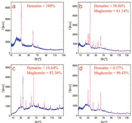
Figure S2 XRD pattern of (a) SH00 (b) SH60 (c) SH120 (d) SH240. The pattern in blue represents the obtained data and the pattern in red is a simulated pattern.
Figure S2 displays the XRD results of SH00, SH60, SH120 and SH240. All the peaks present in the powder X-ray diffraction patterns could be attributed to either hematite or maghemite. By considering their relative intensity one can determine their relative amount.
Supporting Information
1.5
Bulk magnetization property
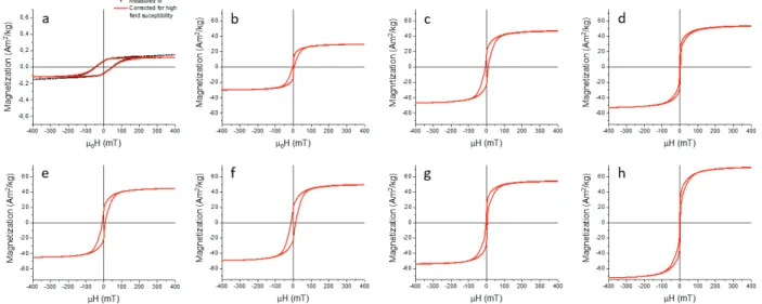
We have studied the effect of the partial transformation on the magnetic properties of the anisotropic particles. The effect of magnetic field on the hybrid nanoparticles was studied by recording the magnetization as a function of applied field strength in a so-called MH loop. From a demagnetized state the field is first swept in one direction (positive field) to saturation, then in the other direction (negative field) until saturation and then again to saturation in the original (positive field) direction again. For all conversion times a hysteresis loop can be seen from the MH curves.
Figure S3 MH loop for (a) SH00 (b) SH10 (c) SH30 (d) SH40 (e) SH60 (f) SH90 (g) SH120 (h) SH240.
1.6
Alignment and self-assembly of hybrid particles at the early conversion stage
At the initial stage of the conversion process, some particles exist with thin strips of maghemite that extend along the width of the ellipsoid. At this stage, lmaghemite< w, where lmaghemite is the width of the maghemite strip, the maghemite domain
contributes to the magnetic moment along the width of the ellipsoid, i.e. along the same direction as the magnetic moment of the hematite majority phase. The stronger magnetic moment of maghemite, leads to a strong magnetization that aligns the ellipsoids perpendicular to the applied filed at low field strength. As the conversion process proceeds further, the maghemite domains broaden so that they are extended along the long particle axis, i.e. lmaghemite> w, resulting in a net magnetic moment that lies
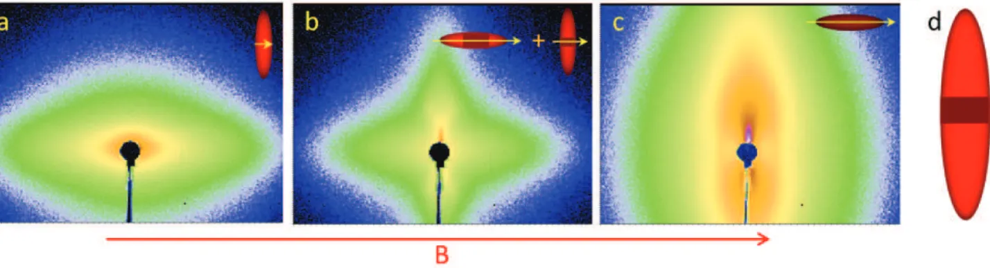
parallel to the long particle axis, which favors parallel alignment. Figure S4(a) shows the scattering pattern for SH00, which is made up of pure hematite and has a magnetic moment that is parallel to the short axis. As a result, the scattering pattern is stretched along the field direction indicating that the particles are aligned with their short axis being parallel to magnetic field. Figure S4(c) shows the scattering pattern for SH60, where we now see that it is stretched perpendicular to the magnetic field, indicating that the maghemite domains in these particles have a larger dimension along the long axis of the particles. Because of these large maghemite domains, the particles are now aligned with their long axis being parallel to the field. In the intermediate conversion time, e.g. 10 minutes, the scattering pattern is not only stretched along the field but also perpendicular to the field (Fig. S4(b)). The origin of this unusual scattering pattern stems from the fact that the ratio of hematite/maghemite shown in the main manuscript (Fig. 1e) represents an average value only, and we expect a quite broad distribution of the resulting volume ratios V(maghemite) = V (hematite) in the individual particles. The SH10 thus consists of two different types of hybrid particles, one with lmaghemite< w and the other with lmaghemite> w, resulting in two different possible alignment of the ellipsoids, perpendicular
and parallel to the field, respectively. This provides clear evidence for two different alignment states, one perpendicular and one parallel to the field direction.
Supporting Information
Figure S4 Magnified diffraction pattern of (a) SH00 and (b) SH10 and (c) SH60 at high magnetic field (1048 mT). The alignment of the particles are shown in the inset. (d) Cartoon of a single particle consists of both hematite and maghemite domains.
The order of magnitude of the typical thickness lc= lmaghemiteat which the particle starts to align perpendicular to the magnetic
field at 3 mT can be calculated by comparing the combined magnetic energy of a thin maghemite disk (shown by dark red in Fig. S4(d)) and rest of the particle which consists of hematite (shown by light red in Fig. S4(d)) with the thermal energy. The volume of a disk of thickness lcand diameter w = 55 nm is:
VM= π · (w/2)2· lc (S1)
Considering the density of maghemite to be ρM= 4900kg/m3and the magnetization of bulk maghemite at 3 mT to be 12.2
Am2/Kg (Fig. S3), the magnetic moment of the disk is found to be ~µM= 142.25 × 10⁻²¹lcJ/T. The magnetic energy of a particle
of magnetic moment ~µM in a magnetic field ~Bis:
UM= − ~µM· ~B= −4.27 × 10⁻²²lcJ (S2)
Now the total volume of a single particle is:
V =4
3π (l/2)(w/2)
2 (S3)
The volume of the portion of the particle which consists of hematite is:
VH= V −VM (S4)
Considering the density of hematite to be ρH = 5300kg/m3 and the magnetization of bulk hematite at 3 mT to be 0.076
Am2/Kg (Fig. S3), the magnetic moment of the hematite domain is found to be ~µH= 1.9657 × 10⁻¹⁹− 0.9587 × 10⁻²¹lc J/T.
The particles will start to get aligned when their thermal energy is compensated by their magnetic energy. By considering this condition we found that the critical thickness lcto be 8.3 nm. This leads us to the conclusion that at lower magnetic field (3 mT)
the SH10 particles align perpendicular when the maghemite strips satisfy the condition 8.3 nm < lmaghemite< 55 nm. However,
once the maghemite strips are large enough to satisfy 55 nm < lmaghemitewe have a parallel alignment of the particles. Hence, by
tuning the conversion time we can also tune the alignment of composite particles.