HAL Id: hal-00983571
https://hal.archives-ouvertes.fr/hal-00983571
Submitted on 4 Sep 2019
HAL is a multi-disciplinary open access
archive for the deposit and dissemination of
sci-entific research documents, whether they are
pub-lished or not. The documents may come from
teaching and research institutions in France or
abroad, or from public or private research centers.
L’archive ouverte pluridisciplinaire HAL, est
destinée au dépôt et à la diffusion de documents
scientifiques de niveau recherche, publiés ou non,
émanant des établissements d’enseignement et de
recherche français ou étrangers, des laboratoires
publics ou privés.
Compact Patch Antenna for Automatic Identification
System (AIS)
Thierry Dousset, Christian Renard, Hubert Diez, Julien Sarrazin, Anne-Claire
Lepage
To cite this version:
Thierry Dousset, Christian Renard, Hubert Diez, Julien Sarrazin, Anne-Claire Lepage. Compact
Patch Antenna for Automatic Identification System (AIS). International Symposium of Antenna
Tech-nology and Applied Electromagnetics (ANTEM), Jun 2012, Toulouse, France. pp.1-5,
�10.1109/AN-TEM.2012.6262302�. �hal-00983571�
Compact Patch Antenna for
Automatic Identification System (AIS)
Thierry DOUSSET, Christian RENARD Thales Systemes Aeroportes (TSA)
Department: RWS-IM/RF-AA Elancourt, FRANCE [email protected]
Hubert DIEZ
Centre National d'Etudes Spatiales (CNES) Department: DCT/RF/AN
Toulouse, FRANCE [email protected] Julien SARRAZIN, Anne Claire LEPAGE
Institut Mines-Telecom, Telecom ParisTech, LTCI Department: Comelec
Paris 13ome, FRANCE
[email protected] - [email protected]
Abstract - This paper presents a radiating element developed
for the space AIS application. This element is a compact sized and reduced mass microstrip patch antenna integrating frequency resonant adjustment devices. Theoretical and experimental results with good agreement are presented.
Keywords: UHF Antenna, Automatic Identification System,
Microstrip Patch Antenna
I. INTRODUCTION
An important emerging application for satellite communications in VHF band is Automatic Identification System (AIS) aimed at detecting messages sent by vessels for maritime tracking, safety and security purposes. Other potential functionalities like fisheries control campaigns, maritime border control operations, maritime pollution survey, search and rescue and anti-piracy can be also investigated.
AIS space segment is constituted of Low Earth Orbit micro or mini satellites which cannot accommodate large VHF antenna (central frequency about 162 MHz). Consequently dimensions and mass constitute two main driving factors for the selection of the antenna solution.
The aim of this paper is to present the antenna solution studied by Thales Systemes Aeroportes (TSA) in collaboration with the French space agency (CNES) and Telecom ParisTech (TPT) Comelec laboratory, for space AIS application.
II. OBJECTNES OF PERFORMANCES
The antenna solution investigated by CNES for the space AIS application is an array constituted of few radiating elements (4 to 6 typically). Depending on the size of the satellite (mini or micro), the array arrangement could be 1 D (linear) or 2D (cross-like arrangement, for example). For
micro-satellite, deployable configurations are also
investigated.
This study was performed under the CNES contract No. 104881100
The main objectives of performances fixed by CNES for the radiating element to satisfy the system and the accommodation requirements are:
- Frequency bandwidth: 162±0.050 MHz (AIS1&2) - Polarization: double linear (H and V)
- Broadside directivity: > 6 dBi
- Reflection coefficient on both ports: Sii:::; -10 dB - Isolation between H/V ports: Sij :::; -20 dB
- Dimensions: L x W x H :::; 50 x 50 x 20 cm - Mass: :::; 5 kg I unit.
Degraded RF-performances could be accepted to respect the dimensional and mass constraints.
III. SOLUTIONS TRADE-OFF ANALYSTS
In the first part of the study, a trade-off analysis between potential solutions has been performed. The RF specifications and the mechanical constraints contributed to eliminate solutions like quadrifilar helix antenna (single circular polarization, prohibitive height), dipole, monopole and PIFA antenna (single linear polarization, insufficient directivity). Finally, the selected radiating element is a dual linearly polarized micros trip patch antenna. This microstrip patch antenna is a pertinent candidate for the AIS application because it is thin profile and potentially low weight solution.
IV. COMPACT MTCROSTRW PATCH ANTENNA
The proposed radiating element is mainly constituted of a square microstrip patch etched on a RogerslTMM6®
substrate (f.,. = 6.00 ± 0.08 and tg8 = 0.023) with a thickness
h = 0.635 cm. It is fed by two 50 Q coaxial probes (one for
each polarization) located on the symmetry axis of the patch [1],[2].
The choice of this specific material, compliant with space application, results from a comparative analysis on the following criteria: dielectric characteristics, specific gravity but also thermal considerations (dimensional expansion and variation of the dielectric permittivity).
In order to reduce the mass of the radiating element, the substrate is truncated all around the patch. The mass reduction induced by this modification is about 1.6 kg. Subsequently, the patch has to be stacked on metallic ground plane (dim. 50 x 50 cm2). In the current configuration, this part which integrates the coaxial probes fixtures and the mechanical interfaces is made of a waffled aluminum plate. The mass of the complete radiating element is less than 3.9 kg. In a further phase of the development, the substitution of the aluminum plate by a composite honeycomb panel will reduce the mass of the antenna about 0.5 kg.
The simulated S-parameters of the isolated patch antenna
are given on Figure I (simulations were performed by TPT
using the software CST Microwave Studio®). The operating
frequency bandwidth (defined for Sii � -10 dB) is about 0.6
MHz (�0.37%) and six times larger than the required range. The isolation Sij between the two ports (H and V polarizations) is better than -35 dB in the required bandwidth. '� ..
�
>"��
1
/
1
i
�
m c,' . "9> " � !Em "'/
1\
-�
" ��
- ---� � ,� 'W l:lli:ill 162 � M ," >C, ,�Figure I: Variation of the S-parameters of the radiating element vs
frequency
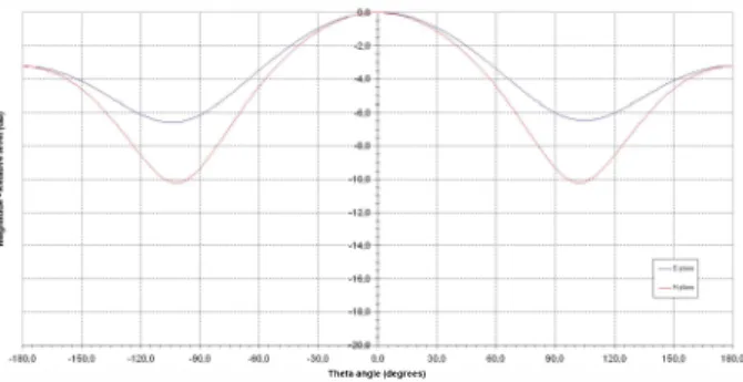
The theoretical directivity of the patch antenna (see radiation pattern on Figure 2) is about 4.5 dBi at the center frequency. This directivity which is lower than the specified value (6 dBi) is due to the small dimensions of ground plane. The theoretical level of the cross-polarization, not represented on this figure, is lower than -34 dB in both principal planes.
The!a .... glel<l·9r�e.)
Figure 2: Radiation pattern of the radiating element at 162 MHz
Complementary simulations have shown that the implementation of a ground plane of dimensions 70 x 70 cm2 would reach the specified value.
V. EFFECT OF THE DIELECTRIC PERMITTIVITY DISPERSION AND ADJUSTMENT DEVICE
The narrow operating bandwidth of the patch element results from the relatively high dielectric permittivity and the
low thickness (h/"- � 0.0034) of substrate whose choices
were imposed by dimension and mass constraints.
At this point, it is important to analyze the effect of the dispersion of the dielectric permittivity on the RF performances of the radiating element and particularly on its RF-matching. The variations of the substrate permittivity have two origins:
- The dispersion from sheet to sheet announced by the
manufacturer (E,-= 6.00 ± 0.08),
- The dispersion induced by the temperature variations during operation in orbit (for the selected material
TMM6®: d£jdT = -II ppm/QC).
In practice, for a same manufactured lot of sheets, a lower dispersion can be obtained. However, for a production that could extend over several years, the whole dispersion range has to be considered.
The effect of the manufacturing dispersion on the S parameters of the patch antenna is shown on Figure 3. A variation of ±0.08 of the dielectric permittivity induces a frequency-shift of about ±1 MHz which is larger than the operating bandwidth (0.6 MHz). -10 ---c---20 ---r- -- ---- ---- ---, --co � -30 --- I- ---I--(/) '" � -40 ;;:. ---1- ---1--·w E .-.-._--- --... --- _5 £ =6 ---;::-�-·t -
::
-, ',:-. _I�_ ._.--- 11 r � -50 -:
;.::-.-=----=---.::-- " \ "\ /-/-" : ... +----.. =; ... .--: .. ::-=-=-:-.. -821 £r=6 � " / I -60 -_.. ---� ..
---_..
- -i-I--'��---i-
________..
-511 £r=6.0a I \i I -821 £ =6.08 -70 ---�
---U
---:
---__ -5 Er=S.92 I I I 11 r:
:
--521 Er=S.92 -8?
55 160 165 170 F"oquence (MHz)Figure 3: Effect of the substrate dielectric permittivity dispersion on the S parameters of the radiating element
These results led us to design an adjustment device for the central operating frequency of the radiating element. This device consists of four sub-devices incorporating etched elements and located in the middle of the four sides of the radiating patch.
Figure 4 shows the evolution of the resonance frequency as a function of the value of one of the adjustment parameters and confirms that it is possible to compensate for manufacturing variations of the substrate.
AdjuslmQnt paramQler (mm) I -+-Epsr=6.08 1 I ___ Epsr=6,OO I -+-Epsr=5,92
1---Figure 4: Variation of the resonance frequency vs. adjustment parameter for three dielectric permittivity values
Concerning the variation with temperature, Figure S gives the theoretical frequency-shift taking into account the dispersion of the permittivity but also dimensional
expansions (in X, Y and Z directions) versus temperature.
The theoretical frequency-shift is less than 2 kHzrc.
1
AIS 1 &2 Bandwidth
1 1 I -Tmed(+5'C) 1 L ______ � --Tmin(55'C) -Frequency (MHz) 1 1
:
-Tmax(+60'C)Figure 5: Variation of the resonance frequency vs. the temperature
Considering an AIS-satellite placed on a SSO orbit, a preliminary thermal study performed by CNES leads to a temperature, at the level of the patch, protected by a thin thermal radome, ranging from -SO°C to +60°C. The resulting frequency-shift is about 0.22 MHz and is less than half of the antenna bandwidth. An initial setting made for an average temperature of +soC will meet the Sjj-parameter specification (Sjj :::;;-10 dB) in the operational space environment.
VI.EXPERIMENTAL RESULTS
During the study, a set of three prototypes of the radiating element have been manufactured and tested by TSA (S-parameters measurements) and CNES (radiation performances measurements: patterns, directivity and gain).
The performances of the isolated patch antennas and, then, of the three elements arranged in a linear array were tested.
Figure 6 gives the measured S-parameters of one of the three patch elements. The analysis of this figure shows that the maximum resonance frequency accessible after adjustment is 160.2 MHz for a design at 162 MHz corresponding to a frequency shift of about 1.1 %.
• E -10.01 ··· ··· ··· ··· ···1'1·· ··· ···,··· · ··· ···1 J � -12.5 � -15.0 ';:.;,:""'���---. __ • � -17.5 ... c .. ·.,=, .. c ... + ... + ,··,,�"', !-20.0 ., ... -Frequency (MHz)
:::::1
l -40.0t' -45.01 ,. -50.0�Figure 6: Measured S-parameters the radiating element (patch #2)
The ongm of the gap between simulation and measurement has been attributed to a discrepancy between the dielectric permittivity measured by ROGERS (for the
considered patch, lOr = 6.0S7 was measured using the Full
Sheet Resonance method) and the effective dielectric permittivity of the patch antenna. To recover the measured resonant frequency, a permittivity equal to 6.23 should be considered in the simulation.
For future development, it will be necessary to take into account the shift between the value of the permittivity measured by ROGERS and the value to be considered for the design, by reducing the patch dimensions, but also to broaden the range of adjustment accessible with the device for adjusting the resonant frequency.
Figure 7 shows a picture of the linear array constituted of
the three radiating elements, with a spacing s = 1.-12 - 92 cm,
mounted on the positioner of the CNES antenna measurement facility.
Figure 7: Linear array of three radiating elements
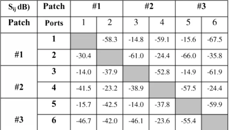
Table I gives the S-parameters simulated (upper part) and measured (lower part) of the three patch elements.
TABLE T. Su-PARAMETERS OF ARRAY AT 160.2 MHZ SijdB) Patch #1 #2 #3 Patch Ports 1 2 3 4 5 6 1 -58.3 -14.8 -59.1 -15.6 -67.5 #1 2 -30.4 -61.0 -24.4 -66.0 -35.8 3 -14.0 -37.9 -52.8 -14.9 -61.9 #2 4 -41.5 -23.2 -38.9 -57.5 -24.4 5 -15.7 -42.5 -14.0 -37.8 -59.9 #3 6 -46.7 -42.0 -46.1 -23.6 -55.4 .. ..
Upper part (SI]): SnTIUlatlOns - Lower part (S]I): Measurements
The analysis of the values in Table I shows a good agreement between measurements and simulations for the ports of same polarization (H-polarization for odd ports and V -polarization for even ports) corresponding to high level of coupling. The origins of discrepancies observed for the ports of different polarizations (HIV isolation) are: small manufacturing defects (patches #1 and #2) and quality of the electromagnetic environment of the array (efficiency of the absorbent panels in VHF band, disturbance caused by the coaxial cables used for the measurements ... ).
Concerning the isolation between ports of the same polarization, the highest values correspond to E-plane coupling (about -15 dB between two adjacent patches) and the lowest values correspond to Hplane coupling (around -23 dB between two adjacent elements). Complementary simulations have highlighted that the mechanical structure around the radiating elements contributes to increase by about 9 dB the E-plane coupling and about 6 dB the H-plane coupling.
CNES has performed radiating measurements with a spherical near field method suitable for small VHF antennas. The antenna radiating patterns have been then deduced by a near-field to far-field transformation. Figure 8 shows the far field radiation patterns of the isolated patch antenna (patch
#2 -port 3 or 4) measured for different <j>-angles round the
axis.
PATCH 2 seul-Acces V3-F=160.2 MHz
Figure 8: Measured radiation pattern of the isolated patch antenna
Figure 9 shows the radiation pattern measured on the port 3 (H-polarization parallel to the array axis) of the same patch placed in the center of the array.
r
�
a
PATCH 2 entoure des des patchs 1 et 3 -Acces V3 sur structure-F=160.2 MHzTHETAIDey)
Figure 9: Measured radiation pattern of the central element in the array (port 3: H-polarization parallel to the array axis)
The comparison of the two previous figures allows to appreciate the modification of the radiating pattern induced by array arrangement for this polarization. Figure 10 shows that the radiation pattern of the polarization perpendicular to the axis of the array (V-polarization), is less disturbed by the arrangement in array. These results are explained by the coupling effects that are higher in the E-plane than in the H plane.
PATCH 2 entoure des patchs 1 et: 3 -Acce�s V4 sur structure-F=160.2 MHz
THETA ID"gl
Figure 10: Measured radiation pattern of the central element in the array (port 4: V-polarization perpendicular to the array axis)
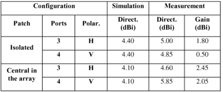
Table II gives the theoretical directivity and the measured gain and directivity of the isolated patch and of the central patch in the array.
TABLE n. DIRECTIVITY AND GAIN OF THE RADIATING ELEMENT (ISOLA TED AND IN THE MIDDLE OF THE ARRAY)
Configuration Simulation Measurement
Patch Ports Polar. Direct. (dBi) Direct. (dBi) Gain(dBi)
3 H 4.40 5.00 1.80
Isolated
4 V 4.40 4.85 0.50
Central in 3 H 4.10 4.60 2.45
the array 4 V 4.10 5.85 2.05
For both cases, the differences between simulations and measurements are explained by the mechanical environment of the element under tests (fixing parts, mechanical interface with the antenna positioner ... ) but also by the measurement
un-accuracy estimated to ± IdB.
For the isolated patch, the differences of directivity and gain between the two polarizations (H and V) are explainable by the presence of the mast antenna positioner.
In the array configuration, the presence of the mechanical structure and of the adjacent radiating elements contributes to increase the gain in both polarizations. The increase appears to be more important for the vertical polarization,
perpendicular to the axis of the array.
These results confirm the performances obtained by numerical simulation for different forms of array and different satellite platforms, namely that the directivity and the gain of the radiating elements depend on their position in the array and polarization (H or V) considered.
VII.FUTURE WORKS
Additional works to be carried out as part of a future development of the solution are:
the refocusing of the radiating element operating frequency band taking into account the effective dielectric permittivity of the substrate,
- the enlargement of the tuning range of the device for adjustment the resonance frequency,
- the qualification of the radiating element in a space environment: mechanical tests (vibration, shock) and thermal (cycles at ambient pressure), thermal vacuum space,
- in a more distant future, the extension of the operating bandwidth of the radiating element to cover both AIS frequency bands (AIS 1&2 and AIS 3&4).
VIII. CONCLUSION
This study allowed us to identify, define and validate a pertinent solution of radiating element, for space Automatic Identification System. The simulations and measurements performed on the prototypes manufactured have proven that the proposed solution is compliant with the RF and integration requirements of the application.
It has been highlighted that this radiating element solution can be used in a conventional phased array (requiring a phase-shifter behind each radiating element) or in an array using the technique of Digital Beam Forming (DBF - requiring one numerical receptor behind each radiating element).
This radiating element of compact dimensions and reduced mass, is compatible with a generic payload on all types of AIS-satellite platform (micro or mini) in a fixed accommodation or a deployable configuration.
ACKNOWLEDGMENT
Thales Systemes Aeroportes would like to thank the French space agency (CNES) that funded the study and for its contribution to the radiation measurements of the prototype antenna.
REFERENCES
[1] K.R. Carver, J.W. Mink - Microstrip Antenna Technology. IEEE Trans. Antenna Propagat., Vol. AP-29, No. 1 pp. 2-24.January 1981. [2] R. Garg and P. Bhartia, Microstrip Antenna Handbook. Boston: