HAL Id: hal-00870339
https://hal.archives-ouvertes.fr/hal-00870339
Submitted on 7 Oct 2013HAL is a multi-disciplinary open access
archive for the deposit and dissemination of sci-entific research documents, whether they are pub-lished or not. The documents may come from teaching and research institutions in France or abroad, or from public or private research centers.
L’archive ouverte pluridisciplinaire HAL, est destinée au dépôt et à la diffusion de documents scientifiques de niveau recherche, publiés ou non, émanant des établissements d’enseignement et de recherche français ou étrangers, des laboratoires publics ou privés.
Functions of Mg and Mg-CaO mixtures in hot metal
desulfurization
David Lindström, Patrice Nortier, Du Sichen
To cite this version:
David Lindström, Patrice Nortier, Du Sichen. Functions of Mg and Mg-CaO mixtures in hot metal desulfurization. Steel Research International, Wiley, 2013, 85 (1), pp.76-88. �10.1002/srin.201300071�. �hal-00870339�
Functions of Mg and Mg-CaO mixtures in hot metal desulphurization
David Lindströma, Patrice Nortierb, and Du Sichenaa Department of Materials Science and Engineering, Royal Institute of Technology,
SE-10044 Stockholm, Sweden
b Laboratoire de Génie des Procédés Papetiers (LGP2), UMR CNRS 5518, Grenoble INP-Pagora
- 461, rue de la papeterie – 38402 Saint-Martin-d’Hères, France
Abstract
The mechanisms of hot metal desulphurization using Mg and Mg-CaO mixtures were studied in a newly designed setup. It was found that most of the added Mg quickly escaped in 2 seconds. MgS was not formed by homogeneous nucleation but by its formation on the MgO particles originated from oxide shell of the Mg particles. When tiny CaO particles (Flucal) were added together with Mg, the particles efficiently transformed to CaS. It was found that Mg-gas helped the distribution of the CaO in the hot metal and improved the kinetic condition. Most of the CaO particles smaller than 10 μm were completely transformed to CaS whereas CaO particles >10 μm still had CaO in the centre after 20 s. The CaO particles as nuclei were also found to help Mg gas in forming MgS. Under the present experimental conditions, a mixture of about 20-30mass% Mg-80-70mass CaO % provided a good utilization of the flux. The reaction products distributed quite well over the whole sample. However, this ratio would need further study in a reactor, as the kinetic conditions would differ considerably. The optimized ratio is expected to be a function of the size and geometry of the reactor, the position and the depth of the addition, the manner of addition and more.
Keywords: Hot metal desulfurization, Mg, CaO, Reaction mechanisms
Introduction
Hot metal desulphurization is an important step to reduce the sulphur level of the liquid metal before converter process. Calcium oxide, calcium carbide and magnesium are the agents commonly used for this task. A number of research works on hot metal desulphurization can be found in the literature. [1-12]. Although magnesium and magnesium-CaO mixtures have been used with success in steel plants, the mechanism of the desulphurization using these agents is still not well known. Industrial studies have shown different degrees of effectiveness of Mg addition. Mg is reported to be able taking down sulphur level from the initial sulphur level typically 300-600 ppm to 10-200 ppm [5,10,11]. Nakanishi injected magnesium granules with carrier gas into a hot metal bath of 15kg to investigate the kinetics of Mg-desulphurization [10]. Irons and Guthrie added vaporized magnesium into hot metal of 60 kg [11]. Both studies showed significant reduction of sulphur concentrations after treatment times ranging from 30 to 60 minutes. While Nakanishi [10] argued that the mass transfer of sulphur in the metal bath was the rate controlling step, Irons and Guthrie [11] believed that the dissolution of Mg-bubble into the hot metal determined the rate of desulphurization. Irons and Guthrie [1] carried out further study in a furnace of 400 kg and developed a model to describe the desulphurization process. They [11] suggested that Mg first dissolved in liquid metal and then met sulphur forming MgS through heterogeneous nucleation on inclusions already present in the melt according to reaction (1).
) (s
MgS S
Mg (1)
In some of the studies [5,6], a slag layer on the top of the hot metal is used. Whether Mg functions in the form of gas bubbles taking down the sulphur content directly or by increasing the sulphide capacity of the slag is always a question. In some of the tests, Mg addition is accompanied or followed by CaO or CaC2 additions [1,4-9]. How the different agents help each other in
desulphurization is still uncertain. Because of the experimental conditions employed, it is very difficult to understand the exact role of Mg in desulphurization, especially when Mg-CaO mixture is employed, and the addition is carried out under industrial conditions (usually in a short period). In view that an in-depth understanding of the mechanism holds the key for process optimization, the present work focuses on an investigation of the role of Mg in desulphurization. A newly designed experimental unit that facilitates (1) precise oxygen potential and temperature control, (2) rapid Mg addition, and (3) rapid quenching of the whole metal bath would ensure the reliability of this investigation.
The setup
In order to study the mechanism of hot metal desulphurization using Mg-CaO mixtures, an experimental setup has been developed. The setup has good control of temperature and oxygen partial pressure in the system. It enables fast flux addition into the hot metal and rapid quenching of the sample after desired reaction time.
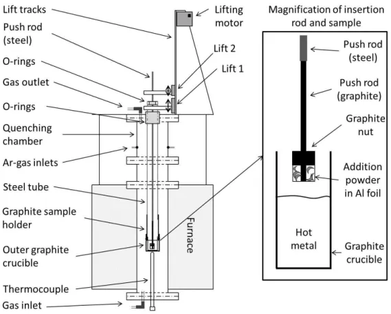
Figure 1. Schematic description of the experimental setup
The fast addition of the flux is absolutely necessary, since magnesium melts at 923K and vaporizes at 1363K. Magnesium must be kept at low temperature before addition. Also, the rapid quenching is essential to understand the mechanism of the reaction when gas phase is involved. The present setup allows the quenching of the sample one second after the flux addition.
The experimental setup is shown schematically in Figure 1. A high temperature furnace with super Kanthal heating elements is controlled using a proportional integral differential (PID) controller supplied by Eurotherm with a B-type thermocouple (Pt-6%Rh / Pt-30%Rh). The sample temperature is followed by B-type thermocouple placed just beneath the holding graphite crucible. Temperature variations in the even temperature zone was less than ±3K.
The reaction tube is made of alumina. It is connected to a water cooled quenching unit made of brass. High temperature resistant rubber O-rings seal the whole reaction chamber and make it gas tight. The quenching unit is equipped with two gas inlets. Argon gas with high flow rate can be injected onto the sample when it is in the quenching position. The use of argon gas would ensure efficient quenching of the sample.
The hot metal is kept in a graphite crucible. A graphite holder attached to a steel tube is used to keep the working crucible. The steel tube is placed in the central axial position from the top of the reaction chamber. A system of rubber O-rings makes it possible to slide the steel tube while at the same time ensuring good sealing. The steel tube is connected to a motor controlled lift (Lift 1) which enabled fast quenching. The lift can move the sample from the hot zone of the furnace to the water quenched unit in less than one second.
A graphite push rod with a graphite nut is used for adding the flux powders to the hot metal. The flux powder is wrapped below the graphite nut with thin Al-foil at the tip of the graphite rod. The details of the graphite rod can be seen in Figure 1 (right side). The graphite rod is connected to a steel push rod, which goes all way through the graphite sample holder and the outer steel tube. O-rings are used to seal the gaps between the outer steel tube and the steel rod. The rod is connected to a second lifting system (Lift 2). The second lifting system can move the graphite rod manually for flux addition, both down and up relative to the first lifting system.
To obtain the oxygen potential of hot metal in the industrial reactors, pure CO gas was equilibrated with the graphite components in the reaction chamber. A Bronkhorst digital mass flow meter was used to control the gas flow rate.
Materials
The pig iron used was supplied by a Swedish steel industry. It had an initial sulphur concentration of 460 ppm (±10 ppm). The sulphur analysis in this study was carried out using LECA combustion analysis (ASTM E1019). All crucibles and graphite parts were made from high purity graphite grade IG 110. The desulphurizing fluxes used in this study were Mg-chips with 99.98% purity supplied by Alfa Aesar and Flucal (a calcium oxide based desulphurizing agent) supplied by Lhoist. The CO-gas had 99.97% purity and was supplied by AGA
Procedure
Each experiment used 250 g of hot metal. Pig iron pieces were placed in a graphite crucible and mounted in the sample holder. The sample was positioned in the even temperature zone of the reaction tube. An amount of 0.402g flux (corresponding to 1.6kg flux per tonne hot metal) was placed at the tip of the graphite rod with a graphite nut and a single layer of very thin aluminium foil. The flux powder along with the nut was initially placed in the quenching chamber, 1.4 m above the hot zone. The temperature in this chamber was about 293 K throughout the whole experiment. The whole system was thoroughly sealed and then evacuated using a vacuum pump for at least 30
minutes. The reaction chamber was thereafter flushed with Ar-gas overnight before being filled and flushed with CO reaction gas upon heating. A constant CO flow (0.1 L/min) was maintained throughout the whole experiment.
After the sample had been heated to 1773K, it was kept at this temperature for 30 minutes to ensure the whole sample being well molten and uniform. Thereafter the graphite rod with the flux unit was rapidly introduced (<0.5 second) into the hot metal with the push rod by hand. This fast addition was found necessary since longer time resulted in melting of the wrapping aluminium foil as well as Mg, and consequently failure of flux addition.
The sample was quenched after predetermined reaction time (2 or 20 seconds) by lifting the holder very fast into the quenching chamber. At the same time, Ar gas with very high flow rate was injected onto the sample holder to ensure efficient quenching.
The sample was removed from the furnace after quenching and prepared for microscopic analysis. A scanning electron microscope (Hitachi S-3700) equipped with EDX was employed. A light optical microscope of (Leica) was also used.
Some of the samples were sent for sulphur analysis. The sulphur analysis in this study was carried out using LECA combustion analysis (ASTM E1019).
Results
Pure Mg addition
To study the function of Mg in hot metal desulfurization, experiments were carried out with pure Mg chips. The amount of Mg was 0.42 grams in all cases. This amount corresponds to 4.8 times of the amount of Mg needed to remove all the sulphur from the hot metal. It is important to mention that strong vibration of the pushing rod was detected when Mg had been added into the hot metal. At the same time noise due to bubbling of Mg gas (simultaneous with the rod vibration) was noticed. The bubbling process (as indicated by the rod vibration and bubbling noise) lasted less than 2 seconds. Quenching of the hot metal bath was done both directly after the bubbling period (2 seconds after Mg addition) or 20 seconds after the Mg addition.
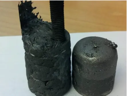
Figure 2 compares the appearances of the samples with and without Mg addition. The left sample quenched 2 seconds after the Mg addition (just after the bubbling period) shows the evidence of strong splashing due to bubble evolution. This is in strong contrast with the sample without Mg addition shown on the right.
Figure 2. Sample quenched 2 seconds after pure Mg addition (left) and reference sample (right). Figure 3 shows a cross section of a hot metal sample which was quenched 2 seconds after Mg addition. The sample quenched 20 second after Mg addition looks similar. Clusters of reaction products were mostly found in the part of the sample very close to the upper surface of the hot metal in both cases (quenched at 2s and 20s). In order to compare the results with the results of CaO-Mg mixtures, the region where the clusters are observed are given in Table 1.
Figure 3. Cross section of the sample quenched 2 seconds after pure Mg addition; the reaction products were found above the black line.
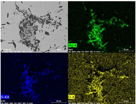
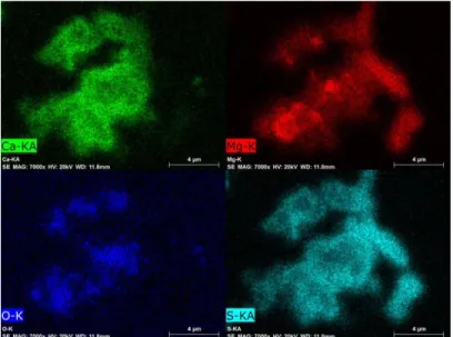
Figure 4 and 5 present the element mappings of the clusters found in the top regions of the samples quenched at 2 s and 20 s, respectively. The co-existence of MgS and MgO is well brought out by the microphotographs in both cases. No pure MgO particle (or cluster) was detected in the two samples. Neither pure MgS particle was found in the samples, though a few particles of MgS with small amount of MgO were occasionally seen.
Figure 4. MgO and MgS co-exist in the upper region of the sample quenched 2 seconds after pure Mg addition (shown by element mappings).
The sulphur contents of the metal after the experiments were analysed by LECO combustion analysis. The sulphur contents were found to be 360 ppm in both samples (quenched 2 and 20 second after pure Mg addition). This content is only somewhat lower than the initial value, 460 ppm, indicating that the desulphurization efficiency using pure Mg is very low.
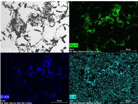
Figure 5. MgO and MgS co-exist in the upper region of the sample quenched 20 seconds after pure Mg addition (shown by element mappings).
CaO-Mg addition
In the study of CaO-Mg mixtures, the lime product from Lhoist, Flucal was employed in all experiments. Different Mg/Flucal ratios were employed (4mass%, 30mass%, 50mass%, 70mass%, 80mass%, Flucal) in order to elaborate the interaction between Mg and CaO in desulphurization. It should be mentioned that vibration of the pushrod and the noise of the bubbling have indicated clearly the escape of Mg gas in all experiments, even when 80 mass% Flucal is used. The vibration of the pushrod is less profound in the case of the mixtures with 70mass% and 80mass% Flucal.
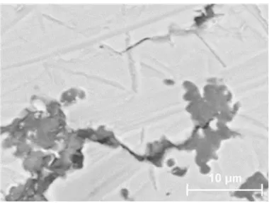
Figure 6. MgS-MgO clusters.
When a small amount of CaO is added together with Mg to the hot metal (Mg-4mass%Flucal), MgS is found together with MgO in clusters, just as in the case of pure Mg addition experiments. The MgS-MgO clusters are found in the upper part of the hot metal. In addition to the MgS-MgO clusters, particles of CaO-CaS phase mixture are also detected in the upper part of the hot metal. The clusters are composed of small particles with a size of 1-10 μm. An example of the cluster is shown in Figure 6.
Figure 7. CaO-CaS and MgS-MgO clusters (shown by element mappings) in the upper part of the sample quenched 20 seconds after Mg-Flucal(4 mass%) addition.
Figure 7 shows the typical element mappings taken from the upper part of the metal bulk, very close to the surface. The sample is quenched 20 seconds after Mg-Flucal(4 mass%) addition. The
cluster of ring shape is composed of mainly CaO and CaS. Even MgS is found in this ring. In the right bottom corner, a cluster of MgO-MgS is seen.
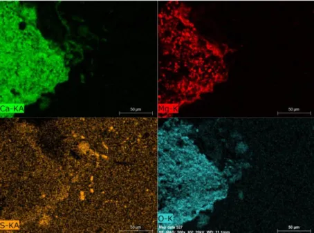
In the cases of Flucal content >30 mass%, clusters consisting of only MgO-MgS are hardly detected. Particles consisting mainly of CaO-CaS are found in the metal bulk. MgS phase is very often found attached on these CaO-CaS particles. This situation is exemplified in Figure 8. The element mappings are taken from the sample quenched 20 seconds after the addition of Mg-Flucal (80mass%).
In general, the added Flucal particles are well distributed by the Mg-gas forming CaO-CaS clusters of 10-50 µm. On the other hand, bigger agglomerated particles are also occasionally detected. Figure 9 presents one example of agglomerated particle, about 300µm in size.
Figure 8. Element mappings showing MgS attached on CaO-CaS particles in the sample quenched 20 seconds after Mg-Flucal(80 mass%) addition
The element mappings of a part of the particle shown in Figure 9 are presented in Figure 10. In contrast with the CaO-CaS clusters, the centre part of the agglomerated particles is still CaO. Only the surface has reacted with the dissolved sulphur in the hot metal. An examination of the Flucal powder reveals no agglomerated particle in the powder. Since no sulphur (see Figure 10) is found in the centre part of the particle, the agglomeration must have taken place very rapidly before the small particles react with sulphur. Note that the particle is found in the sample quenched 2 seconds after Mg-Flucal (4mass%) addition.
Figure 9. Agglomerated CaO particles (about 300μm) in the upper part of the sample quenched 2 seconds after Mg-Flucal(4 mass%) addition.
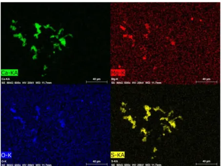
A thorough examination of the samples quenched 20 seconds after Mg-Flucal additions reveals that the transformation of CaO to CaS is size dependent. Most particles of CaO with a diameter less than 10μm have completely transformed to CaS within 20 seconds. On the other hand, particles larger than 20 μm have not been completely transformed. This aspect is exemplified by the element mappings shown in Figure 11. The hot metal was quenched 20 seconds after Mg-Flucal (80mass%) addition. It shows small particles are CaS, while bigger ones are CaO-CaS mixtures. The figure also indicates that MgS has formed on the surface of some CaO-CaS particles (Originally CaO).
Figure 11. Element Mappings taken from the sample quenched 20 seconds after Mg-Flucal(80 mass%) addition.
Reaction product distribution
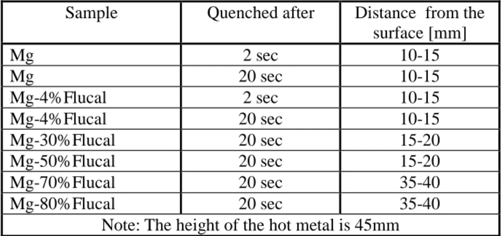
By using scanning electron microscopy and light optical microscopy it was possible to characterize and estimate the distribution of reaction products in the samples. The general trend is that addition with a higher fraction of Flucal results in more particles in the bulk of the sample. The region in which CaO-CaS particles are detected depends on the Mg/Flucal ratio. The distances from the surface of the metal, above which the desulphurization products are detected are included in Table 1. As seen in the table, this distance increases with the decrease of Mg content in the addition. The samples with pure Mg addition and Mg-Flucal (4mass%) addition have reaction products mainly distributed in the area 10-15mm from the top surface. On the other hand, the samples with Mg-Flucal (70mass) and Mg-Mg-Flucal (80mass%) additions have the reaction products distributed over most of the sample.
The presence of CaS particles in the samples make any analysis of dissolves sulphur impossible. Since the present study focuses on the mechanism of the desulphurization, no effort is made to quantitatively describe the desulphurization.
Discussion Mg addition
Figures 4-5 illustrate well the co-existence of MgS and MgO. The same sulphur content and the similarity of the samples quenched at 2s and 20s reveal that the functioning of Mg only lasts 2s,
which is identical to the time Mg bubbling lasts. These results suggest that most of Mg escapes as gas phase in a very short time, when only Mg is added into the hot metal.
It would be important to check how much Mg contributes to desulphurization. To gain this knowledge, it is essential to understand how the particles shown in Figures 4-5 are formed. As shown in these figures, the amounts of sulphur and oxygen in the particles are at the same level. Note that the hot metal contains 460 ppm sulphur and only about 1 ppm oxygen. Since the maximum reaction time is 2 seconds, the mass transfer constraint and low oxygen content in the hot metal would rule out the possibility that Mg reacts with dissolved oxygen and sulphur simultaneously forming the MgS-MgO particles shown in Figure 4-5. It is logical to expect that MgO is from another source than dissolved oxygen.
Note that all the Mg particles have a very thin oxide layer before addition [13]. The oxide layer on each particle would be a source of the MgO shown in Figures 4-5. All the particles in the cluster are less than 1 μm. The small size of the particles supports strongly the argument that MgO found in the upper part of the hot metal is from the oxide shell of Mg particles. This argument is further supported by the fact that all the MgS-MgO particles are found close to the surface of the hot metal. If MgO is from the shell of the Mg particles, the tiny MgO particle should be associated with Mg part, which forms bubble immediately after addition. The Mg gas bubble(s) would lift the tiny MgO-(MgS) particle to the surface of the hot metal. The particles would be left in the upper region of the hot metal, when the gas bubble bursts.
One important observation in the samples with pure Mg addition is that pure MgS particles are not found in the hot metal and neither on the top of the hot metal. While this observation is in line with the above reasoning that MgS forms on MgO particles, the absence of pure MgS particle evidently suggests that MgS is not formed by homogenous nucleation through the following reaction.
MgS S
g
Mg( ) (2) Otherwise, pure MgS particle must have been detected in the samples, especially in the sample 2s after Mg addition.
This reasoning is in good accordance with the conclusion by Irons and Celik. [11] The authors believe that Mg first dissolves in liquid metal and then meets sulphur forming MgS through heterogeneous nucleation on inclusions already present in the melt according to reaction (1). Even Visser and Boom [7] report that MgS form heterogeneously on different inclusions. Visser and Boom did plant trials of hot metal desulphurization with CaO and Mg injection in the transfer ladle of 200 and 250 tons. They found micro sized particles composed of the two phases MgO and MgS sampled immediately after finishing of the Mg injection. Further, they did not find the MgO containing particles (only pure MgS was found), when sampling at the end of the desulphurization treatment which included post injection of CaC2. Though the authors suggested that the absence of
that MgO was transformed to MgS completely since the activity of sulphur was much higher than the activity of oxygen and therefore provided the thermodynamic driving force.
A simple calculation reveals that particles at micro level need rather long time to float up to the upper part of the metal bath. Considering the force balance between the buoyancy force and the drag, the maximum velocity of the particle by floatation would be the terminal velocity,
18 2 MgO Fe t g d V (3)where d is the diameter of the particle, g is the gravitation constant, Fe and MgOare the densities of Fe and MgO respectively, is the viscosity of the metal. The terminal velocity of a MgO particle 1 μm in size is calculated to be 7 1
10 65 .
2
m s
Vt . This extremely low velocity would
rule out the possibility that the particles are moved up to the surface of the metal bath in 2 seconds by floatation. The only explanation to the fact that most of the particles are found near the upper surface is that the MgO particles are lifted by the bubbles.
During the time of rising, MgO particles (brought into the metal by the magnesium chips) react with the dissolved sulphur in the hot metal. Hence, all tiny particles consist of both MgO and MgS. As mentioned in the result part the samples quenched 2 and 20 seconds after Mg addition have the same sulphur content, viz. be 360 ppm. The same sulphur content indicates that most Mg has escaped during the bubbling period, which lasted about 2 s. This is further confirmed by the similarities of the SEM microphotographs of the two samples (Figures 4-5).
A limited sulphur reduction upon Mg insertion in hot metal was also observed by Dyudkin et al. [5]. They did industrial test with Mg-wire insertion for hot metal desulphurization and found that the sulphur level was only reduced from 510 to 400ppm during the 3 minutes that the wire insertion lasted [5].
Irons et al. [1,11] believe that the dissolution of Mg gas into the hot metal is the controlling step for desulphurization. This explains why their addition of Mg lasts more than 30 minutes. Their conclusion is in fact in agreement with the present observation, viz. most of Mg bubbles escape before dissolving into the hot metal. Hence, Mg must be added very slowly to match the slow dissolution and ensure efficient dissolution of Mg.
According to Nakanishi [10], the mass transfer of sulphur in the metal bath was the rate controlling step. As a matter of fact, Nakanishi’s conclusion also agrees with the results of present work, Irons et al.’s work [1,11] and the work by Dyudkin et al.[5]. In Iron et al.’s work, the metal bath is 60 kg or 400 kg. The plume of Mg gas bubbles can sweep big fraction of the total volume of the metal bath. Still, the authors have to add Mg continuously in a long period of time. In a real reactor, the sweeping area of the Mg bubbles is rather limited. Sulphur has to be transferred to the region of the Mg bubbles. Unfortunately, the stirring strength would be very low if the Mg is added slowly
(very small amount of gas bubbles). When the Mg is added in a period of short time, the amount of the gas bubbles generated per second would be very big, like the present case. However, the bubbles would not have time to dissolve into the hot metal. Hence, Nakanishi’s conclusion [10] is also true. The above discussion indicates that one must take all the kinetic conditions into consideration when using the laboratory results for industrial process. Nevertheless, the present work and the literature reveal that in the case of pure Mg addition,
(1) MgS can not form homogeneously.
(2) The dissolution of Mg gas into the hot metal is not fast. In order to use the Mg efficiently, slow continuous addition is essential. Otherwise, most of Mg would escape as a gas phase before dissolving into the metal.
(3) Slow Mg addition might lead to inefficient stir of the metal bath, resulting poor mass transfer in the liquid metal. Additional stirring might be required.
(4) It would be beneficial that other solid desulphurization agent is added along with Mg, so that more heterogeneous nucleation sites are provided for MgS.
Mg-CaO addition
The experimental results clearly show how CaO and Mg interact when a small amount of CaO (Mg-4wt%Flucal) is added together with the Mg to the hot metal. The same observation as obtained in the pure Mg-addition case is also observed here, i.e. MgS is formed on the tiny MgO particles. The Mg-gas quickly brings the CaO particles and MgO pieces (from the surface of the Mg-chips) to the top section of the metal bath, forming clusters. In the raising process, CaO and MgO react with dissolved sulphur forming CaS and MgS. This aspect is evidently shown in Figure 7. As mentioned in the result part, even MgS is found in this CaO-CaS mixture (see cluster of ring shape in Figure 7).
The co-existence of CaO, CaS and MgS are in line with the observation obtained in industrial trials by Visser and Boom [7]. They also found CaS together with MgO and MgS in the iron phase in the region slightly below the top slag layer after combined Mg and CaO blowing in the hot metal transport ladle.
The particles of MgS-MgO mixture are formed by the same mechanism as in the pure Mg addition, viz. the MgS forms by heterogeneous nucleation on MgO originally from the oxide shell of the Mg chips. At the same time, the formation of MgS takes place also by heterogeneous nucleation on CaO particles. This is clearly seen in the cluster of ring shape in Figure 7. In all the samples with the additions of Mg-Flucal mixtures, the existence of CaO, CaS and MgS is seen. This co-existence evidently shows that CaO particles help Mg (possibly dissolved in hot metal) to react with sulphur.
Since the amount of MgO on the Mg chips is very small, the increase of Flucal fraction in the addition leads to a dramatic decrease of the particles containing only MgS-MgO. As mentioned in
the result part, while particles of this type are occasionally seen, they are very hard to find in the samples with additions that have more than 30 mass% Flucal. The CaS is the dominating reaction product in these cases. CaO particles smaller than 10μm would completely be transformed to CaS, as shown in Figure 11. Particles bigger than 10μm consist of CaS-CaO mixture, indicating thereby that the time is not enough for the reaction to complete.
It is worthwhile to mention that the amount of MgS on the CaO-CaS particles seems to increase with the increase of Flucal fraction in the additive, although it is very difficult to provide strong quantitative evidence. Nevertheless, it is definitely true that the amount of MgS on the CaO-CaS particles does not decrease with the decrease of Mg addition. This is in agreement with the results of pure Mg addition. Most of the Mg gas escapes. The observation is also in line with the fact that escape of Mg is noticed in all experiments, even with 80 mass% Flucal. The above discussion suggests that the presence of CaO particles helps the Mg to catch sulphur. It also indicates that an optimization of the amount of Mg in the addition is definitely needed to efficiently utilize the expensive metal.
As discussed above, particles bigger than 10μm does not have enough time to transform into CaS in the present experimental condition. Although the situation in a real reactor could be very different, the present results still illustrate that a certain length of resident time of the CaO particles is required to allow the following reaction to complete,
O CaS S
CaO (4)
As shown in Table 1, bigger fraction of Mg leads to the particle distribution very close to the surface. In the case of additions with 70mass% and 80mass% Flucal the CaS-CaO particles distribute almost all over the whole depth of the metal bath. It is expected that too big fraction of Mg would results in too much gas and therefor would bring the Flucal particles very fast to the metal surface. On the other hand, too small fraction of Mg might not be able to distribute the solid particles sufficiently, consequently leading to particle agglomeration. As seen in Figure 9, agglomerated Flucal particles do not function efficiently due to the small surface area. Hence, an optimized Mg/Flucal ratio is needed to avoid particle agglomeration.
It is worthwhile to point out that the Flucal powder has very small particles and can be kept with its “flowing” condition before usage. Still, bigger particles need more than 20 seconds to transfer into CaS completely. Hence, the use of ordinary commercial lime that has big particle size need to be carefully reconsidered in the desulphurization process using Mg-CaO mixtures.
It should also be mentioned that the addition of pure Mg in the present study can only reduce the sulphur content of the hot metal from 460 to 360 ppm. On the other hand, Irons and Guthrie reduce the sulphur concentration from 624 to 18ppm in a 60 kg metal bath in 60 minutes.[11] The big difference is due to the experimental conditions, viz the addition speed. The two different results strongly suggest that Mg must be added slowly to allow its dissolution into hot metal. In a real reactor, even the mass transfer in the metal phase need to be considered, as the Mg gas generated
by slow addition would not be able to transfer the sulphur to the reaction sites fast enough. Hence, even the addition speed need to be optimized.
It seems that a ratio of about 20-30mass% Mg mixed with Flucal in the present system gives a good utilization of the flux. The reaction products distribute quite well over the whole sample. However, this ratio might not be the optimized value in any reactor. The optimized ratio is a function of size and geometry of the reactor, the position and the depth of the addition, the manner of addition and more. Quantitative optimization with respect to the Mg/Flucal ratio need to be carried out in the reactor employed.
The present result shows also that the stirring generated by Mg gas is rather limited. As pointed out by Nakanishi [10], the mass transfer in a reactor is the controlling step (in fact one of the controlling step according to the present authors). To distribute Flucal particles beyond the region of Mg bubbles, additional stirring like mechanical stirring or inert gas stirring would be of great benefit in improving the desulphurization process and increasing the efficiency of the agents.
Summary
The reaction mechanisms of hot metal desulphurization with pure Mg and Mg-Flucal mixtures were investigated. As indicated by the bubbling, most of the added Mg escaped from the melt in less than 2 seconds. MgS was not formed by homogeneous nucleation but on the MgO particles coming from the surface of the Mg chips added. Since most Mg escaped, the Mg could only reduce the sulphur concentration from 460 to 360ppm. It was evidently shown that Mg must be added slowly over time in order to use it efficiently.
When Flucal was added together with Mg, the Mg-gas quickly distributed the CaO particles. In the raising process, CaO react with dissolved sulphur forming CaS. Particles <10μm were completely transformed to CaS in 20 seconds. Bigger particles were only partly transformed. Agglomeration of CaO particles should be avoided to ensure efficient utilization. The solid CaO particles provided nucleation sites for MgS formation. When the additions were changed to less Mg and more Flucal, the finding of MgO became scarcer and CaS-CaO dominated the reaction products together with MgS.
A mixture of 20-30%Mg/80-70% Flucal seemed to provide the best desulphurization rate under the present experimental conditions. However, this ratio is expected to be a function of the size and geometry of the reactor, the position and the depth of the addition, the manner of addition and etc. Quantitative optimization with respect to the Mg/Flucal ratio need to be carried out for the reactor employed.
The authors are thankful for the financial support and Flucal® supply from Lhoist group and good discussions with researchers of the Nivelles Research Center.
References
[1] G.A. Irons, C. Celik: Ironmaking and Steelmaking, 19 (1992), No. 2, 136.
[2] Y. Weng: Ultra fine grained steels, Metallurgy Industry Press, Springer, Berlin, Heidelberg. 2009, pp.433-435.
[3] D.C. Boyd, W.C. Pheleps, M.T. Hepworth: Metallurgical transactions B, 6B (1975), 87. [4] P.I. Yugov, A.L. Romberg: Metallurgist, 47 (2003), No. 1-2, 62.
[5] D.A. Dyudkin, S.E. Grinberg, S.N. Marintsev: Metallurgist, 45 (2001), No. 3-4, 150. [6] J. Diao, B. Xie, S.S. Wang: Ironmaking and steelmaking, 36 (2009), No. 7, 543. [7] H.J. Visser, R. Boom: ISIJ International, 46 (2006), No. 12, 1771.
[8] H.J. Visser, R. Boom, E. Graveland, A. Overbusch, I. Knorren: Revue de métallurgie, 103 (2006), 487.
[9] A.M. Zborshchik, S.V. Kuberskii, G.Y. Dovgalyuk, K.V. Vinnik: Steel in translation, 41 (2011), No. 9, 741.
[10] K. Nakanishi, A. Ejima, T. Suzuki, F. Sudo: Tetsu To Hagane, 64 (1978), No. 9, 1323. [11] G.A. Irons, R.I.L. Guthrie: Metallurgical transactions B, 12B (1981), 755.
[12] H. Sun, Y.C. Liu, M.J. Lu: Steel Research International, 80 (2009), No. 3, 209. [13] D. Michell, A.P. Smith: Physica Status Solidi B, 27 (1968), No. 1, 291.
Figures:
Figure 1. Schematic description of the experimental setup
Figure 2. Sample quenched 2 seconds after pure Mg addition (left) and reference sample (right). Figure 3. Cross section of the sample quenched 2 seconds after pure Mg addition; the reaction products were found above the black line.
Figure 4. MgO and MgS co-exist in the upper region of the sample quenched 2 seconds after pure Mg addition (shown by element mappings).
Figure 5. MgO and MgS co-exist in the upper region of the sample quenched 20 seconds after pure Mg addition (shown by element mappings).
Figure 6. MgS-MgO clusters.
Figure 7. CaO-CaS and MgS-MgO clusters (shown by element mappings) in the upper part of the sample quenched 20 seconds after Mg-Flucal(4 mass%) addition.
Figure 8. Element mappings showing MgS attached on CaO-CaS particles in the sample quenched 20 seconds after Mg-Flucal(80 mass%) addition
Figure 9. Agglomerated CaO particles (about 300μm) in the upper part of the sample quenched 2 seconds after Mg-Flucal(4 mass%) addition.
Figure 10. Element mappings of the right lower part of the agglomerate shown in Figure 9 Figure 11. Element Mappings taken from the sample quenched 20 seconds after Mg-Flucal(80 mass%) addition.
Table 1. Distance from the surface of the metal above which reaction products are found Sample Quenched after Distance from the
surface [mm] Mg 2 sec 10-15 Mg 20 sec 10-15 Mg-4%Flucal 2 sec 10-15 Mg-4%Flucal 20 sec 10-15 Mg-30%Flucal 20 sec 15-20 Mg-50%Flucal 20 sec 15-20 Mg-70%Flucal 20 sec 35-40 Mg-80%Flucal 20 sec 35-40