OATAO is an open access repository that collects the work of Toulouse
researchers and makes it freely available over the web where possible
Any correspondence concerning this service should be sent
to the repository administrator:
[email protected]
This is an author’s version published in: http://oatao.univ-toulouse.fr/19991
To cite this version:
Cailhol, Simon
and Trajin, Baptiste
and Haussener, Marion
and Vidal, Paul-Etienne
and Carrillo, Francisco Javier
Thermomechanical modelling and simulation of a silicone gel for
power electronic devices. (2015) In: ESREF 2015, 5 October 2015 -
9 October 2015 (Toulouse, France).
Thermomechanical modelling and simulation of a silicone gel for
power electronic devices
S. Caihol
a, B. Trajin
a, *, M. Haussener
a, P.E. Vidal
a, F. Carrillo
a aUniversity of Toulouse, Laboratoire Génie de Production, ENIT- INP, BP1629, 65016 Tarbes Cedex, France
Abstract
The aim of the study is to develop some nodal models describing thermoechanical link in power devices. It is focused on modelling, simulating and testing a component: the silicone gel used in power electronics modules. Due to the future availability of high temperature gel, this study is a first step to establish a multiphysic model. The study aims to establish fast and compact electro-thermomechanical model than can be connected to circuit models, representing other packaging components. In first stage, a finite element model of a commercial gel is defined and some simulation results are presented. In a second stage, an equivalent “electrical” compact model is also suggested and compared to measurements and 3D simulation results. The results presented concern temperature dispatching in both, simulations and measurements, and averaged stresses as well as displacement within the silicone. Future works will describe the thermomechanical link in nodal models, as well as real environment surrounding the silicone gel. Indeed, the silicone thermal expansion impact will be monitored.
Corresponding author.
[email protected]
Thermomechanical modelling and simulation of a silicone gel for
power electronic devices
S. Caihol
a, B. Trajin
a, *, M. Haussener
a, P.E. Vidal
a, F. Carrillo
a aUniversity of Toulouse, Laboratoire Génie de Production, ENIT-INP, BP1629, 65016 Tarbes Cedex, France
Abstract
The aim of the study is to develop some nodal models describing thermoechanical link in power devices. It is focused on modelling, simulating and testing a component: the silicone gel used in power electronics modules. Due to the future availability of high temperature gel, this study is a first step to establish a multiphysic model. The study aims to establish fast and compact electro-thermomechanical model than can be connected to circuit models, representing other packaging components. In first stage, a finite element model of a commercial gel is defined and some simulation results are presented. In a second stage, an equivalent “electrical” compact model is also suggested and compared to measurements and 3D simulation results. The results presented concern temperature dispatching in both, simulations and measurements, and averaged stresses as well as displacement within the silicone. Future works will describe the thermomechanical link in nodal models, as well as real environment surrounding the silicone gel. Indeed, the silicone thermal expansion impact will be monitored. 1. Introduction
This paper deals with multi-physic modeling and simulation of power electronic components and modules. More precisely it is focused on the modeling approach to emphasize the electro-thermomechanical behavior of insulating materials used in power electronics assembly.
Indeed, as encountered in many transport applications, the aerospace industry aims at using more and more electrical equipment. The main idea is to substitute hydraulic and pneumatic systems with electrically fed devices. This lead to increase the number of power electronic device but also the power density of electronics modules due to mutualized power electronic functions. Moreover for additional reasons, the aerospace industry is looking
forward the emergence of wide band gap switches, allowing higher junction temperature. This increase of junction temperature will help fulfilling the current density increasing requirements while reducing the size of the cooling system. However, these new devices will induce new constraints on the packaging material.
This study had been done in the frame of French research program Genome-Premice, which aims at preparing the optimization of the design of on-board energy chains for a new generation of more electric aircraft. Our work takes part in tasks focusing on the evaluation and demonstration of new technologies. More precisely, our study deals with new insulating materials designed to remain functional at higher temperature (>260°C) without any loss of performance.
Considering the temperature expected for these new devices, the silicone-based insulating materials are known to be the weak material of the assembly [1]. They experienced some specific failure modes [2] but also do not behave similarly while ageing.
Although electro-thermal link has been investigated [3], at the moment few studies developed combined electro-thermomechanical models for insulating layer, in order to be inserted in a more macroscopic behavioral simulation of power modules. This is the main purpose of this study.
Extracted from experimental results, multiphysic behavioral models are developed and dedicated to the insulating material. Finally, the comparison allows validating both models. First, a 3D finite element modeling is defined which aims to obtain design rules for power electronic modules. Then, an equivalent electrical compact modeling is proposed. This compact model is validated thanks to finite element simulation. The compact model developed is based on automatic simulation tools and aims at allowing finer real-time control of power modules cooling systems.
2. Silicon gels in power electronic modules 2.1. Power electronics modules generalities
The difficulty of power electronic modules simulation comes from the number of components made of different materials as well as a wide range of scale (from 10 µm to 10 cm). All these components have their own functionalities and the whole module is exposed to multi-physic stresses. Indeed, as depicted in Fig. 1, rounding the semiconductor chip, one can find:
• metallic parts handling electrical conduction, thermal conduction, and/or mechanical holding; • ceramic parts handling electrical insulation,
thermal conduction, and /or mechanical holding; • polymer parts handling electrical insulation
and/or mechanical holding.
Fig. 1. Classical power electronics module architecture
Most of metallic or metallized parts are assembled thanks to solder joints. The differe thermomechanical behavior of the materials involved combined with the device thermal cycling used, leads to strong stresses on the components that can result in the module breaking. It is well known that these parts or attached materials are mostly studied.
2.2. Silicon gels
On the contrary, silicone gel studies are mainly focused on partial discharges or electrical insulating capability. Many studies dealing with ageing of silicone gel used in power electronic modules under passive solicitation are also available. However, ageing process under active solicitation, i.e. using power module as thermal source is rarely on concern [4]. This study is focused on the characterization a modelling of the silicone gels for the simulation of thermal and mechanical management of power 2. Silicon gels in power electronic modules
The difficulty of power electronic modules simulation comes from the number of components as well as a wide range All these components have their own functionalities and the physic stresses. in Fig. 1, rounding the parts handling electrical conduction, thermal conduction, and/or mechanical holding;
ceramic parts handling electrical insulation, thermal conduction, and /or mechanical holding;
polymer parts handling electrical insulation
g. 1. Classical power electronics module
parts are assembled thanks to solder joints. The difference of r of the materials involved thermal cycling when ds to strong stresses on the components that It is well known that these parts or attached materials are mostly
On the contrary, silicone gel studies are mainly r electrical insulating with ageing of silicone gel used in power electronic modules under However, ing process under active solicitation, i.e. using e is rarely on concern his study is focused on the characterization and the simulation of thermal and mechanical management of power
modules. The role of this packaging power electronic component is to both mechanic
and electrically insulate the upper part of the module (notably wire bondings).
Silicone gel should also adhere to different surfaces on the power module in order to avoid corrosion of materials due to Oxygen.
Due to the great role of silicone gel on life span of power modules, their multiphysic behavior and properties have to be studied to ensure that power module are properly operating while ageing high voltage, current and temperature. interaction and potential influence on other packaging components is under consideration. 3. Modelling
3.1. Thermal modelling
Thermal behavior of a system is given using heat equation (see Eq. 1) where T is the temperature, t is the time, k and αare coeff depending on geometry and thermal properties of the material and r is a heat source.
It can be demonstrated that this thermal behavior is equivalent to electrical circuit response composed of resistors representing spatial thermal conductivity, capacitors representing heat storage, voltage sources representing temperature sources and current sources representing heat sources.
Based on such idea, by dividing a volume elements, a nodal model based on association of elementary equivalent electrical circuits may be obtained [5]. Following that, a condensate mathematical form using matrix representation of nodal model is established (Eq. 2), where vector of local temperatures, C is a diagonal matrix of thermal capacities, A the thermal resistances matrix, B is the command matrix and U is the vector of boundary conditions made of temperature or heat sources. In our study case only temperatures sources are considered.
As each elementary volume have a non-nul capacity, C matrix is invertible, Eq. 2
converted into state space representation as given in Eq. 3.
packaging power component is to both mechanically hold and electrically insulate the upper part of the module Silicone gel should also adhere to different surfaces on the power module in order to avoid Due to the great role of silicone gel on life span of power modules, their multiphysic behavior and properties have to be studied to ensure that power while ageing even at high voltage, current and temperature. Their on and potential influence on other packaging components is under consideration.
r of a system is given using heat is the local are coefficients rmal properties of the
(1) thermal behavior composed of resistors representing spatial thermal conductivity, capacitors representing heat storage, voltage sources representing temperature sources and current sources representing heat sources.
volume into a nodal model based on association of elementary equivalent electrical circuits may be condensate matrix representation of
where T is a a diagonal matrix the thermal resistances is the vector made of temperature or heat only temperatures sources
(2) null thermal is easily converted into state space representation as given in
This model is then simulated with classical space simulator. Finally local temperatures at steady state are obtained by solving Eq. 3 with
3.2. Mechanical modelling
Mechanical behavior of viscoelastic silicon gels may be represented by a Burgers material model as depicted Fig. 2, where E denotes elastic modulus and η denotes viscosity.
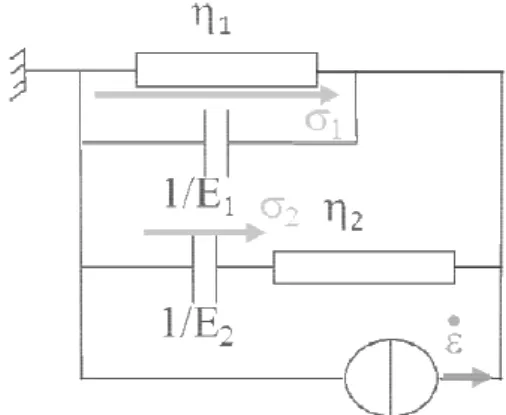
Fig. 2. Viscoelastic Burgers model. Using electro-mechanical analogy [ viscoelastic Burgers model is modeled as electrical circuit composed of resistors and capacitors. Indeed, damper of viscosity ηand spring of stiffness E correspond to resistor of resistance and capacitor of value 1/E respectively. Moreover mechanical subsystems connected in series (resp. parallel) are connected in parallel (resp. series) in the electrical domain. Finally, the Burger model the equivalent electrical model presented in Fig.
Fig. 3. Equivalent electrical circuit of Burgers model.
As for thermal behavior, a nodal equivalent model could be expressed according to Burgers material model. The model linking two
nodes may be expressed by Eq. 4 resulting from electric circuit in Fig 3, where denotes the strain rate applied by the equivalent current source and
(3) This model is then simulated with classical state
local temperatures at steady .
Mechanical behavior of viscoelastic silicon gels may be represented by a Burgers material model [6] denotes elastic modulus
mechanical analogy [7], the modeled as an electrical circuit composed of resistors and and spring correspond to resistor of resistance η
Moreover mechanical subsystems connected in series (resp. parallel) are connected in parallel (resp. series) in the the Burger model leads to
presented in Fig. 3.
. Equivalent electrical circuit of Burgers model.
As for thermal behavior, a nodal equivalent model could be expressed according to Burgers neighbor resulting from denotes the strain rate applied by the equivalent current source and
denotes the derivative along time of the mechanical stress of the two spring (i.e. the two equivalent capacitors).
! "
Based on Eq. 4, it is obvious that the mechanical system can be expressed in one dimension by a system of coupled differential equations corresponding to a state space system. In two or three dimensions, a nodal model represented by a state space system may be established as fo
behavior. The main difficulty lies in the coupling between the different spatial dimensions. Basically, this coupling is achieved through the Poisson’s coefficient. However, this link has to be formalized regarding model in Eq. 4 in further study.
3.3. Thermomechanical modelling
The coefficient of thermal expansion coefficient realizes the link between thermal and mechanical behaviors. It induces displacements depending on temperature and then mechanical stresses. Consequently, in Eq. 4, the input of mechanical model must be correlated to
field (obtained thanks to the thermal model) through the CTE value of the concerned materials. This link is taken into account in finite element simulations performed in section 5.
Moreover, as stated in [8], experimental measurements depicted on Fig. 4 show that dynamic modulus, linked to viscosity η of silicone gel depends on temperature.
Fig. 4. Experimental measurements of dynamic modulus of silicone gel.
denotes the derivative along time of the mechanical stress of the two spring (i.e. the two equivalent
(4)
that the mechanical system can be expressed in one dimension by a system of coupled differential equations corresponding to a state space system. In two or three dimensions, a nodal model represented by a state space system may be established as for thermal behavior. The main difficulty lies in the coupling between the different spatial dimensions. Basically, this coupling is achieved through the Poisson’s However, this link has to be formalized
thermal expansion (CTE) the link between thermal and induces displacements and then mechanical , the input of be correlated to thermal field (obtained thanks to the thermal model) through
materials. This link is taken into account in finite element simulations experimental show that dynamic of silicone gel
This implies that coefficients in Eq. 4 depends on temperature leading to a non-linear system of differential equations. Nevertheless, in this paper, in finite elements simulations, the variation of dynamic modulus according to temperature is neglected and the link between thermal and mechanic model is based on the thermal expansion.
4. Experimental thermal field
A Silgel® parallelepipedic block of dimension 30 by 35 mm length and 15 mm high is prepared in a mold by mixing two components to initiate cross-linking. A particular care is given to the absence of air bubble in the block that could modify thermal properties. Several thermocouples are placed on the middle axis of the block at different heights before cross-linking. After cross-linking, the silicone block is unmold and placed on a heating plate.
The obtained measurements are used to establish reference data for simulations validation.
5. Simulation results
Thermomechanical simulations are performed using finite elements commercial software. A silicone block with the same volume is modelled. Thermal and mechanical parameters are defined according to WACKER Silgel® 616 properties obtained through datasheet or by measurement.
A constant temperature of 74°C is applied on the lower face of the block and an identical convection coefficient is applied on all other faces. The ambient temperature equals 18°C. The convection coefficient is finally adjusted to ensure coherence of results between experimental and simulated data.
Modelling techniques allow simulating any boundary conditions. However, in this study, each face of the block is required to be fixed in translation and rotation. This corresponds to a silicone gel used for volume coating in power electronic devices. It is mechanically linked to substrates and packaging other components due to its adhesive properties. Consequently, thermal elevation, mechanical stresses and displacements are due to external thermal constraint.
5.1. Thermal field
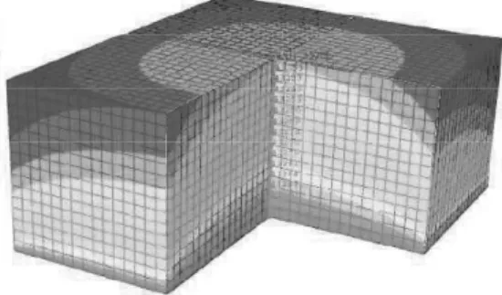
Fig. 5 depicts the thermal field inside of the silicone block. The thermal field is computed using
8-node linear bricks of volume 0.125mm3. Highest (i.e. 74°C) (resp. lowest i.e. 33°C) temperatures are represented in red (resp. blue).
Due to symmetries of the system, the thermal field has a simple geometry.
Fig. 5. Thermal field in silicone gel block.
Moreover, thermal field is also simulated using nodal model with solving Eq. 3 with cubic elements of volume 1mm3. The same parameters than for finite elements simulations are used. Thermal field is similar to the one depicted in Fig. 5. Comparison of experimental, finite elements and nodal method results is given in Table 1 in steady-state conditions. Table 1
Temperature values inside of silicone gel block
Height (mm) Finite elements Simulation (°C) Nodal Simulation (°C) Measurements (°C) 0 74 74 74.2 4 62 63.2 62.5 7 53 54.6 52.0 10 46 46.9 47.2
Moreover, regarding simple geometry and volumes used for elements in nodal model, it may be assumed that this representation is valid regarding results in Table 1. Moreover, it can be seen that the temperature gradient is almost constant in the silicone block along vertical middle axis.
5.2. Transient thermal response
The nodal model used through state space representation in Eq. 3 allows simulating the transient thermal response of the silicone block.
Fig. 6 depicts the temperature variation in the center of the silicone gel block at 0, 4, 7 and 10 millimeters from the heating plate.
Fig. 6. Transient thermal response of silicone block.
5.3. Stress field
Using finite element thermomechanical simulations, Von Mises stresses are monitored inside of the silicone block using 10-nodes tetrahedron elements of volume 0.687mm3. Stress field is depicted in Fig. 7 where highest (i.e. 160 Pa) (resp. lowest i.e. 4 Pa) stresses are represented in red (resp. blue) in steady-state conditions.
Fig. 7. Von Mises stress field in silicone gel block. As illustrated in Fig. 7, it is obvious that stresses have the highest values on boundaries due to non-displacement boundary conditions.
Moreover, highest stresses are lower than elastic modulus of Silgel® 616, ensuring the absence of mechanical degradations inside of the silicone block due to thermal constraints.
5.4. Displacement field
Displacement field inside of the silicone block is depicted in Fig. 8 where highest (i.e. 113 µm) (resp. lowest i.e. 0 µm) displacements are represented in red (resp. blue) in steady state-conditions.
Fig. 8. Displacement field in silicone gel block. It can be observed in simulation that maximal displacement reaches about 100 µm in the middle of the block. This maximal displacement is close to the dimension of power electronics parts such as wire bondings and is located near to wire bonding location. Consequently, depending on adhesive properties of silicone gel on different surfaces of materials, displacement of silicone gel could induce displacement of thin wire bondings. Thus, mechanical stresses may appear in fragile elements such as wire bondings due to thermomechanical effects in silicone gel participating either to mechanical fatigue or break of wire bonding welding. This assumption should be verified through adherence tests and displacement measurements.
6. Conclusion
This work has demonstrated the interest of deeply studying silicone gel used in power module devices due to its thermomechanical behavior and possible effects on components inside of the module. Indeed, it has been proved that silicone gel may induce mechanical stresses inside of the power module. This has to be particularly investigated for new silicone gels adapted to high temperature operations for wide-gap semiconductor technologies that are more and more in used in high integrated power modules.
thermal model based on nodal approximation may lead to a satisfying approximation of internal temperature of a silicone gel block.
Further work will deal with the development of thermal nodal models well adapted to complex geometry of real power modules. Moreover, a similar nodal model based on mechanical behavior of viscoelastic polymers has to be developed and the link between thermal and mechanical behavior has to be formalized. A particular focus will be done on mechanical parameters that depends on stress and temperature.
Finally, this points will be linked with electrical solicitation leading to heat source distribution and finally to thermal and mechanical (stress or displacements) fields inside of the power module.
Another point of interest lies in the simulation of thermal, stress and displacements along time. Indeed, life time of power modules is strongly affected by thermal and mechanical cycling due to electrical solicitations.
References
[1] M. Ciappa, "Selected failure mechanisms of modern power modules," vol. 42, Microelectronics Reliability, 2002, pp. 653-667.
[2] T. Lebey, D. Malec, S. Dinculescu, V. Costan, F. Breit and E. Dutarde, “Partial discharges phenomenon in high voltage power modules”, vol. 13, D. a. E. Insulation, Ed., IEEE, 2006, pp. 810-819.
[3] N. Viviès, M. Haussener, H. Welemane, B. Trajin, P.E. Vidal, “Characterization of an integrated buck converter using infrared thermography,” The 12th International Conference on Quantitative InfraRed Thermography (QIRT), 2014.
[4] T. Thomas; K.-F. Becker; T. Braun, M. van Dijk; O. Wittler, K.-D. Lang: Assessment of high temperature reliability of molded smart power modules, Electronics System-Integration Technology Conference (ESTC), 2014.
[5] M. G. Mario R. Casu, G. Masera, G. Piccinini, M. Zamboni, “Coupled electro-thermal modeling and optimization of clock networks”, Microelectronics Journal, vol. 34, 2003.
[6] A. Malkin, A. Isayev, “Rheology: Concepts, Methods, and Applications”. ChemTec Publishing, 2006. [7] D. C. Karnopp, D. L. Margolis, R. C. Rosenberg,
System dynamics: modeling and simulation of mechatronic systems, Wiley, New-York, 4th ed., 2006. [8] J. G. Drobny, Polymers for electricity and electronics: materials, properties, and applications, Wiley, New-York, 2012.