HAL Id: tel-01304150
https://pastel.archives-ouvertes.fr/tel-01304150
Submitted on 19 Apr 2016HAL is a multi-disciplinary open access archive for the deposit and dissemination of sci-entific research documents, whether they are pub-lished or not. The documents may come from teaching and research institutions in France or abroad, or from public or private research centers.
L’archive ouverte pluridisciplinaire HAL, est destinée au dépôt et à la diffusion de documents scientifiques de niveau recherche, publiés ou non, émanant des établissements d’enseignement et de recherche français ou étrangers, des laboratoires publics ou privés.
Microstructural evolution of a 2.25Cr - 1 Mo steel
during austenitization and temper : austenite grain
growth, carbide precipitation sequence and effects on
mechanical properties
Sylvain Depinoy
To cite this version:
Sylvain Depinoy. Microstructural evolution of a 2.25Cr - 1 Mo steel during austenitization and temper : austenite grain growth, carbide precipitation sequence and effects on mechanical properties. Materials. Ecole Nationale Supérieure des Mines de Paris, 2015. English. �NNT : 2015ENMP0049�. �tel-01304150�
N°: 2009 ENAM XXXX
MINES ParisTech
Centre des Matériaux – UMR CNRS 7633
B.P. 87 – 91003 Evry Cedex, France
École doctorale n° 432 : Sciences des Métiers de l’Ingénieur
présentée et soutenue publiquement par
Sylvain DÉPINOY
le 10 décembre 2015
Evolution microstructurale d'un acier 2.25 Cr – 1 Mo au cours de
l'austénitisation et du revenu : croissance des grains austénitiques,
séquence de précipitation des carbures et effets sur les propriétés
mécaniques
Microstructural evolution of a 2.25 Cr - 1 Mo steel during austenitization and
temper: austenite grain growth, carbide precipitation sequence and effects on
mechanical properties
Doctorat ParisTech
T H È S E
pour obtenir le grade de docteur délivré par
l’École nationale supérieure des mines de Paris
Spécialité “ Sciences et Génie des Matériaux ”
Directeur de thèse : Anne-Françoise GOURGUES-LORENZON Co-directeur de thèse : Ernst KOZESCHNIK
Co-encadrante de la thèse : Caroline TOFFOLON-MASCLET
T
H
È
S
E
JuryM. André PINEAU, Professeur Emérite, MINES ParisTech Président M. Stéphane GODET, Professeur, Université Libre de Bruxelles Rapporteur M. Mohamed GOUNÉ, Professeur, ICMCB, Université de Bordeaux Rapporteur Mme Catherine TASSIN, Maître de conférences, SIMAP, INPG Examinatrice Mme Anne-Françoise GOURGUES-LORENZON, Professeur, MINES ParisTech Examinatrice M. Ernst KOZESCHNIK, Professeur, IMST, Université Technologique de Vienne Examinateur Mme Caroline TOFFOLON-MASCLET, Docteur, CEA Saclay Examinatrice
M. Bernard MARINI, Docteur, CEA Saclay Invité
“It can now be said that the metallurgy of the chromium-molybdenum
steels is almost completely understood and further work can only be
aimed at assessing the effects of modern production processes, scrap
control and minor refinements to composition”
Acknowledgement
En premier lieu, je tiens à remercier Stéphane Godet et Mohamed Gouné d’avoir accepté de relire cette thèse et d’en être les rapporteurs. Je remercie également André Pineau et Catherine Tassin d’avoir accepté d’être membres du jury.
Cette thèse a été encadrée par Caroline Toffolon et dirigée par Anne-Françoise Gourgues. Elles ont su me laisser la part d’autonomie dont j’ai besoin pour travailler tout en me recadrant quand je faisais n’importe quoi. J’ai beaucoup appris à leur contact, que ce soit en termes de connaissances scientifiques, de rigueur ou d’organisation. Je les remercie pour cela. Je remercie également François Roch pour son point de vue industriel qui me faisait totalement défaut en début de thèse, et que j’ai appris à intégrer dans mon raisonnement par la suite. Enfin, bien qu’il ne soit pas officiellement dans l’encadrement, Bernard Marini a été d’une très grande aide, particulièrement en ce qui concerne les propriétés mécaniques et l’algorithme de résolution des équations de croissance de grains.
Un grand merci à tous les docteurs, ingénieurs et techniciens qui m’ont beaucoup aidé au cours de ce travail, à savoir Thomas, Élodie, Stéphane, Didier, Françoise, Jean-Christophe, Denis, Justine, Dominique, Véronique, Marie-Pierre, Jean-Philippe, Jean-Luc, Louis au CEA, Mohamed, Cécilie, Régis et Abdennour aux Mines. Je tiens à remercier particulièrement Sylvain Gailliègue pour son super four trop bien sans qui l’étude du revenu n’aurait pas été possible, ainsi que Pierre Wident pour sa gestion des essais mécaniques.
Je souhaite également remercier légadulabo, Cyan et Freko, et les gars et les filles du labo. Afin d’éviter de froisser quiconque, j’ai décidé de les nommer dans le sens trigonométrique : Gilles “Mango”, un mec en or (surtout change jamais champion), Nicolas “Kopom” et sa tendance à faire masse, Katia “Podzi” malgré sa géométrie euclidienne moralement répréhensible, Isabelle pour ses yeux qui ont une couleur normale, Bertrand pour sa constance à être assorti à lui-même en toutes circonstances et Baptiste, dont le père, pêcheur, a mis toutes les étoiles dans l’eau. Je remercie aussi Benjamin “Ben Hasher” pour m’avoir remercié dans son mémoire de stage (j’attends de lui qu’il me remercie dans sa thèse en retour), Vianney qui prend ma relève dans le photomontage ubique, Pierre pour arriver à avoir l’air encore plus nonchalant que moi, Marine qui partage ma passion pour les ruelles et Alexia “Cappadonna” pour son savoureux durian. Je n’oublie pas non plus Anne-Laure et Julie qui ont partagé mon bureau, Emma pour son aide concernant les répliques extractives, Pauline, Danny boy, William, Camille, Esther, Juan, Nesrine, Emilie, Mickael, Vincent et plusieurs Olivier (tout ça au CEA), de même que Guillaume, Alexandre, Lucie, Hubert et Victor (aux Mines). J’en place une dernière pour Breton, Paul et Bédouche pour ces longs débats intellectuels que nous avons menés à Bordeaux, Mathilde parce qu’elle est cool et Thomas pour l’intégralité de son œuvre (mais alors vraiment l’intégralité).
Je n’oublie bien évidemment pas mes parents qui m’ont soutenu tout au long de ces trois années avec des frites et du bœuf bourguignon, ainsi que mes frères Falzar et Scooter. Je dédie cette thèse à mon grand-père Gilbert, disparu en 2014, et à ma grand-mère Marie-Rose.
Enfin, je remercie Elisa pour son soutien au quotidien lors de la rédaction de ce manuscrit. Le résultat final aurait été très probablement de moins bonne qualité sans elle, et ma santé mentale bien plus dégradée.
En revanche, je ne remercie pas Freddy Mercury. Mon seul regret concernant cette thèse est de ne pas avoir étudié un acier inoxydable, tant cela m’aurait permis d’introduire ce manuscrit par une merveilleuse citation de Method Man. Mais bon, tant pis.
7
Résumé
Le travail qui suit porte sur l’optimisation des propriétés mécaniques et microstructurales d’une pièce épaisse d’acier 2.25 Cr – 1 Mo à travers l’utilisation des traitements thermiques. Ce manuscrit est découpé en 6 chapitres qui sont brièvement résumés ici.
Le premier chapitre est un résumé des propriétés générales de l’acier 2.25 Cr – 1 Mo que lui confère sa composition chimique et ses propriétés microstructurales. Afin de satisfaire aux exigences en terme de propriétés mécaniques en vigueur dans l’industrie nucléaire, cet acier doit préférablement être sous forme bainitique avec le moins de ferrite proeutectoïde possible. La précipitation de carbures qui a lieu au cours du traitement de revenu lui donne ses propriétés mécaniques finales et conditionne également sa durée de vie. De plus, l’acier 2.25 Cr – 1 Mo présente une bonne résistance aux phénomènes de fragilisation par vieillissement thermique et par irradiation susceptibles d’avoir lieu au cours de sa vie, que ce soit en conditions normales ou accidentelles. Il est également montré que l’utilisation de 2.25 Cr – 1 Mo enrichi en vanadium, bien que présentant des avantages certains pour l’application classique de cet acier (industrie pétrochimique), n’est pas intéressante dans le cas étudié ici. Enfin, les différents types de traitements thermiques sont présentés, ainsi que leurs influences sur la microstructure finale : l’austénitisation et la trempe à l’eau ont un effet sur la matrice, alors que le revenu n’influence que l’état de précipitation des carbures. Un dernier traitement thermique dit de détensionnement est appliqué à la fin du processus de fabrication de la pièce épaisse, et n’a a priori pas d’effet notable sur la nature des phases constituant le matériau.
Le second chapitre rassemble plusieurs études préliminaires nécessaires à la bonne conduite de l’étude à proprement parler. La composition chimique moyenne de la pièce servant à usiner les échantillons est étudiée, puis comparée à un matériau dit de référence avec lequel les propriétés mécaniques futures sont comparées. Ces deux matériaux sont issus de la même virole de 280 mm d’épaisseur. Il est à noter que la composition chimique moyenne est quasiment identique dans l’épaisseur de la pièce. Le diagramme de phase à l’équilibre tel que déterminé à l’aide des logiciels MatCalc et ThermoCalc est discuté. Il en ressort qu’à l’exception des carbures, auxquels un chapitre entier est dédié, les seules phases secondaires potentiellement intéressantes sont les AlN, susceptibles d’agir sur la croissance du grain austénitique, et les MnS, qui servent de site de germination pour la rupture ductile. Les vitesses de refroidissement au cours de la trempe à l’eau sont ensuite calculées en utilisant l’équation générale du transfert thermique. En effet, à cause de la forte épaisseur de la pièce considérée, des gradients thermiques apparaissent au cours du refroidissement et sont susceptibles d’aboutir à des hétérogénéités microstructurales, telles que celles illustrées par un diagramme TRC obtenu après une condition d’austénitisation particulière. Enfin, des hétérogénéités locales de composition, dites microségrégations, sont mises en évidence. Elles n’affectent toutefois que très légèrement les propriétés mécaniques locales du matériau. A l’issue de ce chapitre, il apparait donc d’une part que les échantillons étudiés sont bel et bien représentatifs de la pièce dans son ensemble, et d’autre part qu’il est nécessaire de déterminer une condition d’austénitisation
8
permettant une bonne homogénéité microstructurale de la pièce après trempe. Cette dernière problématique fait l’objet des chapitres 3 et 4.
Dans un premier temps, l’étude de la croissance du grain austénitique en fonction du temps et de la température d’austénitisation est abordée. Le but de ce chapitre est de développer un modèle permettant de calculer le diamètre moyen des grains austénitiques en prenant en compte la pression motrice due à la courbure du joint de grain et les pressions de freinage dues à des phénomènes d’épinglage et de trainage de soluté (solute drag). Avant de pouvoir développer le modèle, des mesures expérimentales pour des températures allant de 920°C à 1120°C et des temps d’austénitisation allant jusqu’à 2 heures sont effectués. Il apparait qu’à des températures inférieures ou égales à 970°C, un phénomène de croissance limitée intervient. Pour des températures supérieures ou égales à 1070°C, la croissance est dite parabolique, c’est-à-dire qu’elle ne dépend que de la pression motrice. Entre ces deux régimes, à 1020°C, la croissance est ralentie mais pas limitée. Une analyse statistique de la distribution en diamètre des grains montre que la croissance est normale quelle que soit la température. En utilisant le modèle cinétique de précipitation de MatCalc, il apparaît que l’épinglage dû aux particules d’AlN seules ne permet pas d’expliquer la croissance limitée aux basses températures. En revanche, l’ajout d’un terme correspondant au trainage d’atomes de molybdène piégés aux joints de grains donne des résultats proches de l’expérience, et ce pour des paramètres cohérents avec ceux trouvés dans la littérature. En conclusion, il est proposé que la croissance des grains austénitiques dans l’acier étudié soit principalement contrôlée par ce phénomène de trainage de soluté. Cette conclusion est toutefois à tempérer par le fait que le modèle ne prend en compte qu’un seul grain, et ne permet donc pas d’estimer les interactions existantes entre les différents grains.
L’étude de l’effet des conditions d’austénitisation sur les propriétés microstructurales et mécaniques après trempe et revenu fait l’objet du 4e chapitre. Huit différentes conditions d’austénitisation sont étudiées pour trois différentes vitesses de refroidissement représentant des épaisseurs caractéristiques d’une pièce épaisse. En dehors de l’effet attendu de la taille du grain austénitique sur les transformations au refroidissement, il apparaît que les conditions d’austénitisation n’ont qu’un effet très limité sur les propriétés microstructurales telles que la taille du paquet bainitique ou l’état de précipitation. De même, il est impossible de mettre en évidence un effet de l’austénitisation sur les propriétés en traction et en résilience. Il est toutefois très intéressant de noter qu’à 920°C, le temps d’austénitisation a une influence considérable sur la fraction de ferrite transformée au refroidissement, et ce pour une taille de grain très similaire. L’explication proposée renvoie à la ségrégation du molybdène aux joints de grains lors du traitement d’austénitisation, potentiellement couplée à des phénomènes de solute-drag like effect (SDLE). En conclusion, une austénitisation à 970°C pendant 1 heure donne de bons résultats en termes d’homogénéité microstructurale et de propriétés mécaniques ; il est donc décidé de l’utiliser pour l’étude du traitement thermique de revenu.
L’effet du temps et de la température de revenu sur la précipitation des carbures est étudié dans le chapitre 5. Les températures étudiées vont de 650°C à 725°C pour des temps allant jusqu’à 24 heures. En raison d’une vitesse de chauffage très lente, une attention particulière a été portée aux
9
évolutions microstructurales ayant lieu lors du chauffage. Dans l’acier étudié, cinq différents types de carbures sont susceptibles d’être observés, dans l’ordre de leur stabilité thermodynamiques croissantes : M3C, M2C, M7C3, M23C6, M6C. Ces carbures présentent chacun des propriétés
morphologiques, cristallographiques et chimiques bien spécifiques. En particulier, la composition en éléments métalliques M est propre à chaque carbure : il est donc aisé de les différencier par une simple analyse EDX. Les évolutions microstructurales sont caractérisées par des observations au MET sur des répliques extractives. Des analyses par diffraction des Rayons X sur de la poudre de dissolution sélective sont également effectuées afin de déterminer la fraction massique de chaque type de carbure en fonction du temps et de la température de revenu. Il est important de souligner qu’aucun M6C n’est observé, quelles que soient les conditions de revenu, en bon accord avec les
calculs thermodynamiques qui prédisent un domaine de stabilité pour ces carbures à des températures bien plus faibles que celles étudiées. Au vu des résultats obtenus, la séquence de précipitation des carbures au cours du traitement thermique de revenu peut être décrite comme suit : lors du chauffage, l’austénite résiduelle présente entre les lattes bainitiques et aux anciens joints de grains austénitiques se décompose en ferrite et en cémentite M3C. En chauffant à plus haute
température, les carbures M2C, M23C6 et M7C3 commencent à précipiter. Les deux premiers germent
dans la matrice et dans les dislocations se trouvant à l’intérieur des lattes bainitiques, alors que les carbures M7C3 germent à l’interface entre la cémentite et la matrice et croissent aux dépens des M3C.
Lors du palier isotherme, les carbures d’équilibre M23C6 croissent et provoquent la dissolution des
carbures les moins stables, M2C d’abord et M7C3 ensuite. L’augmentation de la température
augmente la cinétique de ces dernières transformations.
Le dernier chapitre s’emploie à mettre en évidence la relation entre le traitement thermique de revenu et les propriétés en dureté, en traction et en résilience. D’une manière générale, l’augmentation du temps et de la température de revenu provoque un adoucissement du matériau. Lors du chauffage et des premières heures de revenu, cet adoucissement est majoritairement dû à des phénomènes de restauration des dislocations. Pour des temps plus longs, le grossissement ou la dissolution des carbures M2C non-cisaillables est tenu pour responsable. Il convient de préciser que
l’adoucissement dû à la restauration de dislocations est bien plus important que celui résultant de l’évolution des carbures. Les conditions de revenu n’ont pas d’effet mesurable sur les propriétés en résilience. Toutefois, les courbes de transition ductile-fragile obtenues sont remarquables par l’étroitesse du domaine mixte ductile-fragile. L’effet du traitement de détensionnement a également été brièvement étudié : bien qu’il n’ait pas d’effet sur la dureté, un adoucissement est observé lors des essais de traction. Ce résultat contre-intuitif reste inexpliqué. Tout comme le revenu, le traitement de détensionnement n’a pas d’effet sur les propriétés en résilience.
11
Table of contents
C
HAPTER
I:
B
ACKGROUND
,
OBJECTIVES AND APPROACH OF THE
STUDY
... 17
C
HAPTER
II:
M
ATERIALS UNDER STUDY
... 27
1. Materials ... 27
1.1 As-received material ... 28
1.2 Reference material ... 29
2. Phase transformations and equilibrium ... 31
2.1 Equilibrium calculations ... 32
2.2 Transformations upon heating ... 34
2.3 Equivalent cooling rates ... 35
2.4 Phase transformation behavior during cooling (CCT diagram) ... 37
3. Chemical heterogeneities ... 39
3.1 Spatial distribution of chemical composition ... 40
3.2 Effect on local mechanical properties ... 43
3.3 Effect on phase transformations ... 44
4. Conclusion ... 45
C
HAPTER
III:
E
XPERIMENTAL CHARACTERIZATION AND MODELLING
OF AUSTENITE GRAIN GROWTH
... 47
1. Modelling austenite grain growth ... 48
1.1 General framework of modelling ... 48
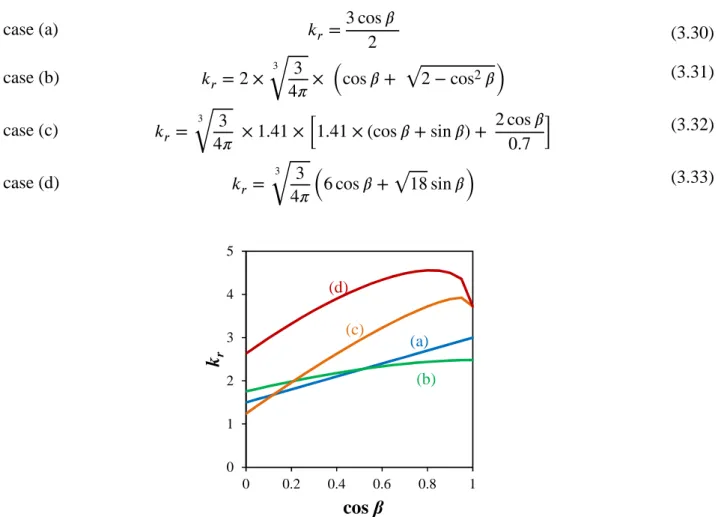
1.2 Grain growth kinetic exponent: grain growth with no retarding pressure ... 50
The parabolic growth law ... 50
The signification of the kinetic exponent ... 50
Activation energy associated to the effective grain boundary mobility ... 51
1.3 Retarding pressures ... 51
Pinning effect ... 52
Solute drag ... 57
2. Experimental investigations ... 60
2.1 Experimental approach ... 60
2.2 Grain size homogeneity ... 62
2.3 Analysis of the phenomenological kinetic exponent ... 64
3. Modelling limited growth mechanisms ... 65
3.1 Driving pressure versus Zener pinning ... 65
Modelling approach ... 65
Determination of the driving pressure ... 66
Table of contents
12
Results and discussions ... 68
3.2 Modelling solute drag during austenite grain growth ... 69
Selection of values of diffusivity X and binding energy E0 ... 69
Setting up the model ... 71
Results and discussion ... 72
4. Conclusion ... 75
C
HAPTER
IV:
E
FFECT OF AUSTENITIZATION CONDITIONS ON THE
MATERIAL PROPERTIES AFTER COOLING AND TEMPERING
... 77
1. Literature review ... 78
1.1 Effect of austenitization temperature on austenite decomposition upon cooling ... 78
1.2 Morphology of cooled microstructures ... 79
1.3 Carbide precipitation ... 80
1.4 Effect on mechanical properties ... 80
2. Experimental study ... 81
2.1 Choice of experimentally studied austenitization conditions ... 81
2.2 First investigation: effect of austenitization conditions on the decomposition of austenite upon cooling... 82
Lowest cooling rate (0.3°C/s) ... 83
Intermediate cooling rate (1°C/s) ... 88
Higher cooling rate (3°C/s) ... 90
Summary: austenite decomposition upon cooling ... 92
Selection of austenitization conditions for further microstructural characterizations and assessment of mechanical properties ... 92
2.3 Further investigations on selected austenitization conditions ... 93
Effect of austenitization conditions on microstructures cooled at the quarter-thickness equivalent cooling rate ... 93
Influence of the austenitization conditions on mechanical properties ... 96
3. Conclusion ... 98
C
HAPTER
V:
C
ARBIDES PRECIPITATION DURING TEMPERING
... 99
1. Literature review: Carbide precipitation in 2.25 Cr – 1 Mo steels ... 100
1.1 Precipitation sequence ... 100 1.2 Carbide characteristics ... 101 M3C carbides ... 102 M2C carbides ... 102 M7C3 carbides ... 104 M23C6 carbides ... 104 M6C carbides ... 104
Summary of carbide characteristics ... 106
1.3 On the nucleation of carbides ... 106
Table of contents
13
2.1 Thermodynamic calculations ... 107
Stability diagram ... 109
Chemical composition inn metallic elements of carbides at equilibrium ... 109
2.2 Experimental characterization ... 111
TEM observations, EDX analyses and electron diffraction ... 111
X-Ray diffraction on electroetching residues ... 114
3. Effect of tempering conditions on the carbide precipitation ... 115
3.1 Experimental results ... 115
Carbide precipitation upon heating ... 116
Carbide evolution upon tempering: effect of time and temperature ... 119
Effect of stress-relieving heat treatment on carbides ... 127
3.2 Discussion ... 127
Evolution of carbides upon tempering heat treatment ... 127
Summary of precipitation sequence ... 130
4. Conclusion ... 131
C
HAPTER
VI:
M
ECHANICAL PROPERTIES AFTER TEMPERING
... 133
1. Literature review: effect of tempering conditions on mechanical properties ... 133
1.1 Resistance to deformation and strengthening mechanisms ... 135
1.2 Toughness properties ... 138
2. Experimental results ... 138
2.1 Effect of tempering on mechanical properties ... 139
Hardness measurements ... 139
Tensile properties ... 144
Impact toughness properties ... 146
2.2 Effect of stress-relieving heat treatment on final mechanical properties ... 148
2.3 Determination of Temper Parameter coefficient ... 151
3. Conclusion ... 153
C
ONCLUSION AND OUTLOOKS
... 155
R
EFERENCES
... 159
A
PPENDIX
A:
E
XPERIMENTAL PROCEDURES
... 171
1. Heat treatments ... 171
1.1 Austenitization in an induction furnace ... 171
1.2 Tempering ... 174
2. Microstructural observations: microscopy and microanalysis ... 174
2.1 Optical microscopy: metallographic observations and austenite grain size measurements . 174 Metallographic observations ... 174
Table of contents
14
2.2 Scanning electron microscope: carbon extraction replicas, EBSD and fractography ... 176
Observation of carbides on carbon extraction replicas ... 176
EBSD ... 177
Fractography ... 177
2.3 Carbide characterization using transmission electron microscopy ... 177
2.4 Quantification of segregations using electron probe microanalysis ... 177
3. Characterization of carbides using X-Ray diffraction techniques ... 177
3.1 X-Ray diffraction and sample preparation by selective dissolution ... 177
3.2 Synchrotron X-Ray diffraction ... 178
4. Thermal properties ... 179
4.1 Characterization of phase transformations using dilatometry ... 179
4.2 Determination of ferrite-austenite transformation temperatures using calorimetric measurements ... 180
4.3 Determination of the thermal diffusivity using Laser flash analysis ... 180
5. Mechanical testing ... 180
5.1 Hardness and nanoindentation ... 180
5.2 Tensile tests ... 183
5.3 Impact toughness tests ... 183
A
PPENDIX
B:
T
HERMOKINETIC CALCULATIONS
... 185
1. Nucleation in multicomponent systems ... 185
1.1 Nucleation energy barrier ... 185
1.2 Number of available nucleation sites ... 186
1.3 Zeldovich factor ... 187
1.4 Atomic attachment rate ... 188
2. Mean-field evolution equations for precipitate growth ... 188
2.1 System description ... 188
2.2 Total Gibbs energy and its dissipation rate in the system ... 189
2.3 Evolutionnary equations ... 191
A
PPENDIX
C:
C
HEMICAL COMPOSITION OF CARBIDES AFTER HEAT
TREATMENTS INVOLVING DIFFERENT AUSTENITIZATION CONDITIONS
193
A
PPENDIX
D:
T
HERMOKINETIC MODELLING OF THE CARBIDE
PRECIPITATION SEQUENCE
... 195
1. General framework ... 195
2. Model assumptions ... 195
2.1 Matrix ... 195
2.2 Carbides ... 196
2.3 Nucleation and growth parameters ... 197
Table of contents
15
3.1 Evolution of carbide phase fractions ... 198
3.2 Size evolution of carbide ... 199
3.3 Amount of elements in solid solution ... 200
3.4 Limitation of the model: evolution of the chemical composition of carbides ... 201
3.5 Effect of stress-relieving heat treatment ... 202
17
Chapter I: Background, objectives and approach
of the study
Light water reactors (PWRs, BWRs) are representing 80% of the world nuclear plants. In France, PWR constitutes the reference solution for the renewal of EDF reactors. This will lead to a massive use of PWRs at least until the end of the 21st century. Thus, there will be coexistence between those
reactors and the 4th generation reactors. On an international level, the renewal of 2nd generation light water reactors may also be provided by PWR or BWR until at least the middle of the century. Thus, safety and technological improvements of light water reactors represent key issues.
In this framework, the 2.25 Cr – 1 Mo steel (15 CD9-10), designated by the ASTM A387/ASME SA387 and by ASME A508/A508M-14 Grade 22 standard (Table 1.1), is being considered as potential candidate pressure vessel material for future light water reactors. The two main reasons are its good fracture toughness (in particular low temperature value of the start of the upper shelf) and its very good resistance to radiation-induced embrittlement compared to usual pressure vessel steels. Moreover, its good weldability is interesting regarding the manufacturing of a thick-walled pressure vessel [1].
C Mn P S Si Cr Mo
SA387 0.05-0.15 0.25-0.66 0.035 max 0.035 max 0.50 max 1.88-2.62 0.85-1.15
A508 0.11-0.15 0.30-0.60 0.015 max 0.015 max 0.35 max 2.00-2.50 0.90-1.10 Table 1.1: Chemical composition as specified by the ASME SA387 and ASME A508 Grade 22
standard (wt%)
These steels have been widely used in pressure vessels for the petrochemical industries for decades due to their good mechanical properties at high temperature [2, 3]. In such applications, the typical operating temperature ranges from 300 to 480°C under high hydrogen partial pressure, in the range of 15-200 bars. On the other hand, for nuclear applications, the operating temperature is around 300°C under irradiation due to thermal neutrons. These two different operating conditions require different specifications. The mechanical standards set by the RCC-M for nuclear pressure vessel steels is summarized in Table 1.2. These requirements for tensile properties are easily met for a 2.25 Cr – 1 Mo in the quenched and tempered condition [4].
Good properties of 2.25 Cr – 1 Mo are due to the chemical composition of the steel as well as to its microstructure. For instance, the presence of chromium gives satisfactory resistance to corrosion and oxidation [5] (although a stainless steel cladding remains needed for nuclear applications), while both chromium and molybdenum improve the creep resistance [6]. A low Sulphur content is also recommended, since this element reduces the upper shelf impact energy (USE) [7], and a low phosphorus content allows to prevent a thermal aging at the service temperature and to limit the irradiation embrittlement as it will be shown later.
1. Materials
18
Quenched and tempered 2.25 Cr – 1Mo steels are fully bainitic. It is worth mentioning that bainite after cooling in 2.25 Cr – 1 Mo steels is granular bainite [8–10]. This particular type of bainite is free from carbides before tempering, and austenite is retained along lath boundaries. A fully bainitic matrix gives an optimum for tensile and toughness properties, as well as creep resistance, compared to proteutectoid ferritic matrix [5, 11]. While the occurrence of 2% of proteutectoid ferrite does not change the mechanical properties [12], it is generally advised to minimize the proteutectoid ferrite fraction [13].
Test Test
temperature Characteristics
Requirements
Axial direction Azimutal direction
Tensile RT Min Rp0.2 400 MPa Rm 550/670 MPa Min A% 20 350°C Min Rp0.2 300 MPa Min Rm 497 MPa KV Impact toughness 0°C Min average 80 J 80 J
Min individual value 60 J 60 J
-20°C Min average 40 J 56 J
Min individual value 28 J 40 J
20°C Min individual value 104 J 120 J
Table 1.2: Mechanical standards for nuclear pressure vessel steel as given by the RCC-M In the case of thick-walled component such as pressure vessels, it is thus mandatory that the microstructure remains homogeneous throughout the thickness, from the skin, where the cooling is very fast, to the mid-thickness, where the cooling is slower. 2.25 Cr – 1 Mo steels exhibit good bainitic hardenability due to their chemical composition. The two main alloying elements, chromium and molybdenum, are known to delay the ferritic transformation towards lower cooling rates upon continuous cooling, while the bainitic transformation critical cooling rates remain unaffected [10]. This effect is counter-intuitive when considering the ferrite-stabilizing nature of these elements, and is usually explained by their strong affinity with carbon, impeding carbon diffusion and therefore delaying the decomposition of austenite. On the other hand, austenite-stabilizing elements such as carbon and manganese are usually advised to be at the upper bound of the requirements, in order to improve the bainitic hardenability [12].
Final mechanical properties and their evolution at operating temperature are given by the carbides. In the general case of a quenched+tempered bainitic steel, carbide precipitation can occur during the decomposition of austenite upon cooling, or upon subsequent tempering. A detailed literature review and information regarding these carbides can be found in Chapter V. In chromium steels, several carbides can coexist: the cementite (Fe,Cr)3C, and alloyed carbides (Cr,Fe)7C3 and
(Cr,Fe)23C6. In molybdenum steels, possible carbides are (Fe,Mo)3C, Mo2C and (Mo,Fe)6C. The
precipitation sequence upon tempering in bainitic 2.25 Cr – 1 Mo steels is well-known, and has been determined by Baker & Nutting as [14]:
Chapter I: Background, objectives and approach of the study
19
ε-carbide → M3C + M2C → M7C3
↓ ↓
M23C6 → M6C
where ε-carbide are the precursors of the cementite M3C, and “M” stands for the metallic elements.
M2C carbides, due to their fine dispersion and their coherency with the matrix, are partially
responsible for the good strength of the 2.25 Cr – 1 Mo steels. For instance, they are held responsible for the good creep properties [15] and possible secondary hardening [16]. Upon ageing, these metastable carbides are progressively replaced by M6C with increasing time and temperature [14,
17], leading to a loss of mechanical properties over use. Precipitation of these Mo-rich carbides also reduces the amount of molybdenum in solid solution, leading to an increase in susceptibility to tempering embrittlement. However, since this sequence of precipitation is triggered by diffusion, these carbides can be considered as relatively stable at low working temperature: for instance, in petrochemical applications, the life service of 2.25 Cr – 1 Mo steel is beyond 20 years at an operating temperature in the range of 520-560°C [17]. At the end of its lifetime, the steel typically exhibits large, blocky M6C carbides located at boundaries, providing pathways for crack propagation and thus
leading to further embrittlement.
Along with this loss of mechanical properties due to the carbide evolution, four other embrittlement mechanisms can take place depending on the application. Under hydrogen atmosphere, hydrogen embrittlement and hydrogen attack are susceptible to occur. For nuclear applications, embrittlement due to neutron irradiation is of major concern. Furthermore, thermal ageing can induce temper embrittlement, depending on the steel purity.
Temper embrittlement is due to the segregation of chemical species at prior austenite grain
boundaries, resulting in an increase in the fracture appearance transition temperature (FATT) and in a loss of toughness. It should be pointed out that the fully bainitic structure is more susceptible to temper embrittlement than a ferritic structure [18, 19]. Temper embrittlement depends on the chemical composition: phosphorus, tin, antimony and arsenic co-segregate with alloying elements, such as silicon and manganese. The susceptibility to temper embrittlement can be estimated through empirical factors like J-factor (expressed as a function of wt%) or the Bruscatto factor 𝑋̅ (expressed as a function of wt-ppm), given respectively in equations (1.1) and (1.2).
𝐽 = (Mn + Si) × (P + Sn) × 104
(1.1)
𝑋̅ = (10 P + 5 Sb + 4 Sn + As) 100⁄ (1.2)
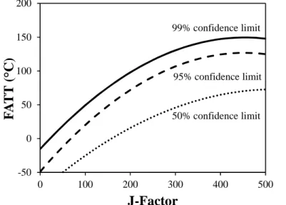
The fracture appearance transition temperature (FATT) of 2.25 Cr – 1 Mo type steels has been correlated to the J-factor: Low values of J-factor lead to very low values of FATT after in-service use, and thus after thermal ageing (Figure 1.1). Consequently J-factor has to be kept as low as possible mainly by controlling the impurity content of the steel.
In rather large quantity relatively to the other elements, phosphorus is the most deleterious element, since its segregation at parent austenite grain boundaries promotes intergranular fracture
1. Materials
20
and could lead to an increase in FATT. Manganese and silicon are only promoting phosphorus segregation. Thus, reducing their concentration leads to a decreased susceptibility to temper embrittlement [20]. It should be pointed out that chromium and nickel also promote phosphorus segregation. At the opposite, molybdenum is known for reducing phosphorus segregation upon thermal ageing when in appropriate content [21, 22]. Increase in parent austenite grain size also leads to increase in susceptibility to temper embrittlement. The temper embrittlement susceptibility of the 2.25 Cr – 1 Mo steel can be optimized by setting phosphorus and other embrittling elements, but also silicon and manganese at their lowest possible content allowed both by requirements and steelmaking process constraints. In the case of manganese, this advice is in conflict with the considerations on the bainitic hardenability, thus a good compromise has to be found.
Figure 1.1: Effect of impurities (J-factor) on the fracture appearance transition temperature (FATT). Probability curves based on historical data collection for base and weld metals, aged from 20 000
hours to 200 000 hours. From [2]
Hydrogen embrittlement is a phenomenon that can occur below 300°C if the ingot is cooled
below this temperature before the application of the de-hydrogeneization treatment. The defects that could appear are known as flakes. For chemical plant vessels, this phenomenon is also considered when the vessel is cooled too quickly upon shutdown, where the hydrogen dissolved in the steel during operation cannot escape and is therefore retained at lower temperatures. Hydrogen embrittlement leads to a lower threshold stress for crack propagation, and can also result in the loss of adherence of the stainless steel cladding to the wall of the pressure vessel [23].
This phenomenon is not possible in nuclear pressure vessel in nominal service conditions the hydrogen content remains low during operation (very small H uptake from the primary circuit coolant and H generation by transmutation ((n, p) reactions). Hydrogen embrittlement decreases the minimum value of stress intensity for crack propagation more significantly than temper embrittlement, and interactions between these two embrittlement phenomena results in further reduction of this minimum stress intensity factor [24].
-50 0 50 100 150 200 0 100 200 300 400 500
F
A
TT
(
°C
)
J-Factor
50% confidence limit 95% confidence limit 99% confidence limitChapter I: Background, objectives and approach of the study
21
Higher strength steels are more sensitive to this phenomenon than lower strength steels as shown in Figure 1.2 [6, 23], and 2.25 Cr – 1 Mo steels with a tensile strength lower than 100 ksi, i.e. 689 MPa, are considered as resistant materials to hydrogen embrittlement [6].
Figure 1.2: Effect of dissolved hydrogen concentration on fracture toughness of 2.25 Cr – 1 Mo steel of various tensile strengths. From [23]
Hydrogen attack is another degradation process due to the presence of hydrogen in solution in
the material. Unlike hydrogen embrittlement, such phenomenon takes place at higher temperatures, above 300°C. Hydrogen attack occurs when dissolved hydrogen reacts with carbon and form methane bubbles, leading to an irreversible loss of strength, ductility and toughness, and even to blistering or cracking [24]. The safe operating limits in terms of pressure and temperature are assessed by the Nelson diagram, which is built from experience-based curves (Figure 1.3). For 2.25 Cr – 1 Mo steels, at 300°C, the maximal partial hydrogen pressure is approximately 1.5 MPa. A lacking parameter in such representation is the applied stress, which enhances the rate of bubble nucleation [25]. Thermal stress and residual stress have the same effect as that of applied stress.
Figure 1.3: Nelson curve for 2.25 Cr – 1 Mo steels. From [23] 0 25 50 75 100 125 150 175 200 225 0 2 4 6 8 10
K
(
M
P
a
.m
1 /2)
Dissolved hydrogen (ppm)
UTS: 725 MPa 790 MPa 860 MPa 0 100 200 300 400 500 0 5 10 15 20 25T
em
p
er
a
tu
re
(
°C
)
P
H2(MPa)
Safe operating conditions Hydrogen attack
1. Materials
22
2.25 Cr – 1 Mo steels have typically a higher resistance to hydrogen attack than plain carbon steels, due to two factors that reduce the growth rate of methane bubbles: stable carbides and high creep strength. Stable carbides trap carbon atoms, which are then not available for the methanation reaction, while high creep strength induces elastic back-stress around isolated bubbles, impeding their growth. The presence of chromium and molybdenum improves the resistance to hydrogen attack for several reasons: they are strong carbide formers, they reduce the activity of nearby carbon atoms, and in the case of molybdenum, its segregation at grain boundaries tend to reduce the grain boundary energy, making the formation of new free surfaces more difficult [6]. Further addition of vanadium, tungsten, boron, titanium, niobium, tantalum, zirconium and yttrium reduces the susceptibility to hydrogen attack, either because they are strong carbide formers (V, W, Ti) or by acting as hydrogen traps (V, Ti, Nb, Ta, Zr). Other elements, such as Sn or Si, increase the methane density and bubble diameter.
Due to the susceptibility to hydrogen attack, the maximum operating temperature for 2.25 Cr – 1 Mo steels in hydrogen service is 454°C, as given by the API 941 standards. These requirements are largely met for the nuclear industry, where the nominal operating temperature does not exceed 300°C, for a much lower partial pressure of hydrogen.
Neutron irradiation upon service induces microstructural changes on low-alloy steels by
creating structural defects, such as dislocation loops and cavities, and enhancing solute diffusion, leading to precipitation, formation of solute clusters and eventually phase transformations. These microstructural changes are responsible for evolution of mechanical properties, for instance increase of tensile strength and ductile to brittle transition temperature (DBTT), reduction in fracture toughness and loss in the upper shelf energy (USE). This embrittlement is correlated to chemical elements present in the steel. Nickel, manganese, silicon, as well as impurities like copper and phosphorus are known to segregate under irradiation, and tend to form nanoclusters in the matrix, along dislocation lines and at metallurgical interfaces. Among all these elements, only copper could be above its solubility limit and precipitates easily. Copper-enriched nanoclusters are often enriched in manganese, silicon, nickel and phosphorus. However, in the absence of copper, nanoclusters of manganese and nickel as well as of phosphorus are still observed. Neutron radiation is also known to favor phosphorus segregation to metallurgical interfaces and in particular to prior austenitic grain boundaries, possibly leading to intergranular fracture qualitatively comparable to temper embrittlement [26]. The average size and composition of nanoclusters does not change with the fluence, however their number density increases almost linearly with the fluence [27–29].
Copper, nickel and phosphorus are recognized as the most deleterious elements regarding radiation-induced embrittlement. Embrittlement due to irradiation can be divided in two categories: hardening and non-hardening effects. Hardening effects are due to the formation of point defects and solute clusters, while non-hardening effects are based on the same mechanisms as temper embrittlement, i.e. segregation at prior austenite grain boundaries. For instance, copper nanoclusters causes hardening embrittlement, while radiation induced phosphorus segregation falls in the second category as already stated regarding temper embrittlement. Nickel enhances radiation embrittlement by both mechanisms, since it forms nanoclusters but also nickel phosphides at grain boundaries, causing reduction in cohesive strength of grain boundaries and thus leading to grain boundary
Chapter I: Background, objectives and approach of the study
23
embrittlement [30, 31]. Thus, nickel content in steels is clearly correlated to their sensitivity to radiation-induced embrittlement, as shown in Figure 1.4.
Recently, new Russian RPV steels (Modified 15Kh2MFA-A, close to 2.25 Cr – 1 Mo but with V), have been proposed. The authors of these works conclude to a better resistance of these steel to thermal ageing and irradiation embrittlement at 300°C because of their low Ni content. When clean, i.e. with low amounts of copper and phosphorus, the only mechanisms of radiation-induced embrittlement is due to hardening caused by creation of structural defects, and a low Ni content reduces the density of these defects, improving the radiation resistance of the steel. The standard V-free 2.25 Cr – 1 Mo provides a similar advantage with a wider industrial background.
Figure 1.4: Dependence of irradiation induced DBTT shift on nickel content. Phosphorus and copper contents are 0.010% and 0.05%, respectively. Irradiation temperature: 270°C, fluence: 1024
neutron/m². From [30]
It is known that the amount of chromium also plays a role in radiation-induced embrittlement especially for high Cr content when α-α’ decomposition is involved. However for 2.25 Cr – 1 Mo steel, this type of ageing mechanism is not expected. As an illustration of the effect of Cr, 5% Cr steels and 9% Cr steels experience less degradation of their toughness properties after irradiation at high doses at 365°C than 2.25% Cr steels, but 12% Cr steels exhibit less resistance to radiation-induced embrittlement than 2.25% Cr steels in the same irradiation conditions [32].
As a result, careful control of the chemical composition results in good resistance to embrittlement upon ageing. Low phosphorus and copper contents and reduced content of Ni compared to usual RPV steels makes the 2.25 Cr – 1 Mo steel less susceptible to temper embrittlement and radiation-induced embrittlement. In the considered operating conditions, hydrogen attack should not occur but limited hydrogen embrittlement could exist for long time of operation, and 2.25 Cr – 1 Mo has a good resistance to this type of damage.
A wide range of modified 2.25 Cr – 1 Mo chemistries have been designed since the first use of 2.25 Cr – 1Mo steels, to improve either the bainitic hardenability or the mechanical properties. The most widespread one is the 2.25 Cr – 1 Mo – 0.2 V, where some vanadium is added to the steel. Such
0 25 50 75 100 125 150 0 0.5 1 1.5 2
∆
D
B
T
T
(
°C
)
C
Ni(%)
1. Materials
24
chemical modification improves the material strength and resistance to hydrogen attack, and allows the material to be used at temperatures up to 510°C against 454°C for conventional 2.25 Cr – 1 Mo steel, regarding the API 941 standard for hydrogen service [33]. Such improvement of mechanical properties is due to precipitation of relatively stable, fine vanadium carbides which stabilize a fine dislocation substructure within the bainite [34]. However, addition of vanadium only has little effect on the steel hardenability [12]. Other modified 2.25 Cr – 1 Mo steels for petrochemical applications include addition of niobium, titanium, manganese, nickel or even boron [12, 34–37]. Such additions tend to increase the bainitic hardenability as well as the mechanical properties. However, in the present industrial application, such modifications of the material composition do not appear mandatory. Operating conditions are by far less aggressive than in the petrochemical industry: partial pressure of H2 is negligible compared to the petrochemical industries, and the working temperature,
around 300°C, is well below the maximal operating temperature as given by the API 941 standard. Other chemical elements, such as nickel or boron also considered in modified chemistries are detrimental regarding the resistance to irradiation-induced phenomena.
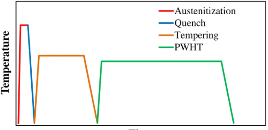
In the present study, the chemical composition of the steel is already defined, as well as the steelmaking process. Thus, the only adjustable parameter leading to optimize the mechanical properties is the microstructure. Microstructural parameters are controlled through heat treatments conducted upon the industrial manufacturing of the component, after the forging stages. These heat treatments are summarized in Figure 1.5.
Figure 1.5: Schematic diagram showing the different heat treatment applied on the material after forging. PWHT: Post-weld heat treatment.
The first step is austenitization, where the steel is heated in order to transform its microstructure from a mixture of carbides and body-centered cubic ferrite into a single face-centered cubic austenite phase where all carbon atoms are in solid solution. After austenitization, the component is quenched; upon quenching, the austenite decomposes into the final matrix microstructure. A tempering heat treatment is then applied, where almost all carbon atoms in solid solution precipitate into carbides. The stress-relieving heat treatment, or post-weld heat treatment, is the last heat treatment applied on the material. It is typically conducted at lower temperatures than the tempering heat treatment, and aims at reducing the residual stresses in the material that have been introduced by welding. No
T
em
p
er
a
tu
re
Time
Austenitization Quench Tempering PWHTChapter I: Background, objectives and approach of the study
25
obvious microstructural changes are expected upon this last heat treatment compared to the microstructure before welding.
The aim of this work is to improve the understanding of the effects of heat treatments on phase transformations and microstructural evolution, as well as their effect on the mechanical properties. Microstructural evolution was experimentally investigated on various heat treatments, and models were used in order to quantify the contribution from different mechanisms on this evolution. In this manuscript, each heat treatment is investigated on after the other, as in the real targeted process.
Chapter II is dedicated to the study of the as-received material in terms of chemistry and microstructure. Comparison is made with a reference material. Thermodynamic equilibrium calculations, characterization of chemical variations throughout the component and determination of the cooling rates of interest is also made in order to prepare further experimentations. A first austenitization is applied in order to test the material bainitic hardenability, which does not give satisfactory results.
In the considered industrial application, the component is water quenched thus cooling rates after austenitization are not a process parameter. Under this constraint, bainitic hardenability can only be improved by increasing the austenite grain size upon austenitization. Thus, Chapter III and IV are dedicated to the study of microstructural evolution during austenitization, to optimize conditioning of austenite for further decomposition and tempering.
In Chapter III, the effect of austenitization on microstructural evolution of austenite is experimentally investigated as a function of temperature and time. Mechanisms controlling the austenite grain growth, such as Zener pinning and solute drag, are then postulated and discussed thanks to a modelling approach.
Chapter IV is dedicated to the effect of austenitization on microstructural and mechanical properties after cooling at different rates representative of different locations in the thickness of a large component. It should be pointed out that while the bainitic hardenability is of interest, the bainitic transformation mechanism itself has not been studied. This choice is justified by the fact that the final mechanical properties are mostly due to the precipitation of carbides within the bainite, and that a good bainitic hardenability is mandatory for the considered industrial application. On the other hand, several assumptions about the decomposition of austenite into proteutectoid ferrite, and more precisely on the means for delaying this transformation, are made. Based on the study of the grain growth mechanisms and the characterization of microstructures after cooling, an austenitization condition is selected for the subsequent study of carbide precipitation upon tempering.
The carbide precipitation sequence upon both heating up to the temperature of interest and the isothermal step of tempering is studied in Chapter V. Evolutions of size, phase fraction and chemical composition of carbides have been quantitatively determined. Based on these experimental data, mechanisms for nucleation and growth of carbides are then proposed; a thermokinetic modelling approach has been tested to discuss these mechanisms and is presented in Appendix D.
In the last Chapter VI, the effect of tempering conditions on the strength and toughness properties is reported, as well as the effect of the final stress-relieving heat treatment.
27
Chapter II: Materials under study
T
ABLE OF CONTENTS
1. Materials ... 27
1.1 As-received material ... 28 1.2 Reference material ... 29
2. Phase transformations and equilibrium ... 31
2.1 Equilibrium calculations ... 32 2.2 Transformations upon heating ... 34 2.3 Equivalent cooling rates ... 35 2.4 Phase transformation behavior during cooling (CCT diagram) ... 37
3. Chemical heterogeneities ... 39
3.1 Spatial distribution of chemical composition ... 40 3.2 Effect on local mechanical properties ... 43 3.3 Effect on phase transformations ... 44
4. Conclusion ... 45
Prior to the study of the effects of heat treatments on microstructural and mechanical properties, the material itself had to be characterized thoroughly.
The studied 2.25 Cr – 1 Mo steel was provided with two different states: the so-called as-received material, which was considered as the initial state, and the reference material, which had been industrially reheated and was used as a means of comparison. In a first part, the thermal history prior to this study is described for both states, as well as their chemical composition and microstructure. Moreover, the effect of the component thickness on these properties is briefly reported. In a second part, material properties useful to the study of microstructural transformations during heat treatments are described. Among them, the equilibrium state was estimated using thermodynamic simulations. The general behavior of the steel regarding austenitization and quench was studied. Equivalent cooling rates, corresponding to representative thicknesses in the ingot, were also determined. Finally, the chemical homogeneity in the material was studied in order to ensure that every sample is characteristic of the whole piece.
1.
M
ATERIALS
Two different states of the studied material were supplied: the as-received state and the reference state, which was industrially reheated. This latter will be used as a mean of comparison, mostly for mechanical properties but also for microstructural properties in Chapter IV.
1. Materials
28
1.1
As-received material
The as-received material was a 280 mm thick cylindrical shell forged from a 186-ton hollow ingot fabricated at Industeel-Le Creusot (formerly Creusot-Loire Industries) in 1994. Heats were melted in an electric furnace and then underwent a heating ladle refinement. The hollow ingot was casted by bottom pouring of two heats. After hot forging, the hollow shell underwent an austenitization at 990°C for 10 hours followed by water quench, then several tempering heat treatments, the last one being at 660°C for 12 hours followed by air quenching. After these heat treatments, the piece of metal was cut into two halves through its center perpendicular to its axis. Both halves were then welded, joining the top and the bottom of the forged component. A final heat treatment at 690°C for 10 hours was then performed on the welded component. Samples used through this study were machined from a 420x450 mm² blank taken from the quarter-thickness and from the top of the as-received forged component.
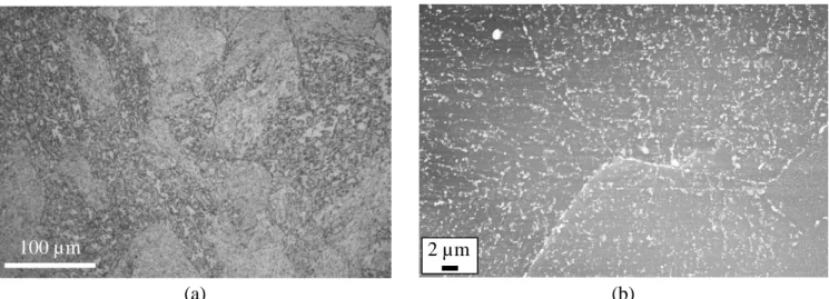
Composition of the steel measured after different steps of its processing history is shown in Table 2.1, the “heat” chemical composition being the average of the two heats used for casting. The resulting microstructure is tempered bainite with carbides located at the interfaces, as shown in Figure 2.1. Since this material was to be reheated for the purpose of the present study, no detailed characterization of its microstructural and mechanical properties was conducted except for chemical homogeneity as described at the end of this chapter.
C S P Si Mn Ni Cr Mo V Cu Al N
Heat 0.14 0.004 0.004 0.22 0.53 0.16 2.43 1.07 N/A 0.04 0.014 N/A Product 0.14 0.003 0.005 0.23 0.53 0.16 2.44 1.09 <0.01 0.06 0.012 N/A ¼ th 0.15 0.003 0.006 0.24 0.51 0.17 2.47 1.11 <0.01 N/A 0.008 0.007
Table 2.1: As-received steel composition (wt%). Heat and Product compositions are given by AREVA, ¼ thickness composition is given from an independent analysis
(a) (b)
Figure 2.1: Microstructure of the as-received material, (a) optical microscopy (etchant: Nital 4%) and (b) SEM observation of carbides on a carbon extraction replica.
Chapter II: Materials under study
29
1.2
Reference material
As already stated, all samples used in this study come from the quarter-thickness of the as-received material. In order to estimate their representability when compared to the whole hollow component, thorough analysis of thermal gradient during heat treatments and chemical composition across the thickness were done.
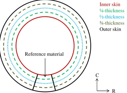
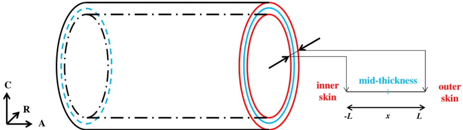
These studies were conducted on the so-called “reference material”, which comes from the same hollow component as the as-received material as schematized in Figure 2.2. In the hollow component, one must differentiate the quarter-thickness, located halfway between the inner skin and the mid-thickness, and the three quarter-thickness located halfway between the outer skin and the mid-thickness. Location in thickness might have an effect on the chemical composition due to possible segregations that happened during casting.
Figure 2.2: Schematic diagram of the different locations of interest and geometry of the reference material component.
The reference material has undergone the same thermomechanical processing and prior heat treatments as the as-received steel, as well as further heat treatments:
• Austenitization at 930°C, then water quenched.
• Tempering at 675°C. The heating rate was 2°C/min, and the component was then air cooled.
• Stress-relieving heat treatment at 645°C for 16 hours. The heating rate was 15°C/h, and the cooling rate was 20°C/h.
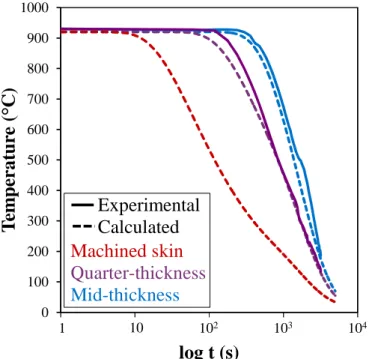
Due to the large thickness of the component, a thermal gradient occurs during the heating and cooling stages of the heat treatments. Temperatures at locations of interest, namely the skin, the quarter-thickness, the mid-thickness and the three-quarter thickness were monitored during each step of these heat treatments. K-type thermocouples were inserted into holes drilled from outer skin to quarter-thickness, mid-thickness and three-quarter thickness. Another set of thermocouples were welded at the skin; two thermocouples were used for each location. The stress-relieving heat treatment was carried out with only the skin thermocouples. It should be pointed out that the
Inner skin ¼-thickness ½-thickness ¾-thickness Outer skin Reference material C R
1. Materials
30
geometry of the reference material part is not the same as that of the prior hollow component. Indeed, the first one has a symmetry axis corresponding roughly to the mid-thickness, thus the thermal gradient at quarter-thickness and three quarter-thickness is expected to be the same during all heat treatments. In the case of the prior hollow component, one could imagine that cooling rates would be different at inner and outer skins upon quenching (and by extension at the quarter-thickness and the three quarter-thickness), for instance because of local heating of the water inside the component. However, its large inner radius, namely 4360 mm, allows the water to behave the same way whether it is inside or outside the component. Thus, all thermal gradients measured in the reference material are considered representative of the industrial hollow component.
Heating rates are slow enough to be considered as homogeneous across thickness, so are the cooling rates after tempering and the stress relieving heat treatment. As expected considering the symmetry of the piece, no differences were found between the quarter-thickness and the three-quarter thickness during heat treatments. However, the isothermal steps durations and the cooling rates after austenitization change across the thickness, as shown in Table 2.2.
Location in the thickness Inner skin ¼ and ¾-thickness ½-thickness Austenitization time (h) 2 1.5 1
Cooling rates after austenitization (°C/s) 10 0.5 0.3
Tempering time (h) 6 5.5 5.5
Table 2.2: Isothermal step durations for austenitization and tempering and cooling rates after austenitization at different locations of the forged component.
After heat treatments, the resulting part was cut into four pieces corresponding to the four locations of interest in the component thickness. The chemical composition remains the same through the thickness, as shown in Table 2.3. Moreover, the average composition through thickness is similar to the one at the quarter-thickness of the as-received steel as shown in Table 2.1, thus this one can be considered as chemically representative of the whole component.
C S P Si Mn Ni Cr Mo Al N Skin 0.14 0.003 0.007 0.23 0.52 0.16 2.47 1.13 0.011 0.007
¼ th 0.15 0.003 0.005 0.23 0.52 0.16 2.48 1.13 0.010 0.007
½ th 0.15 0.003 0.005 0.23 0.52 0.16 2.46 1.09 0.010 0.007
¾ th 0.14 0.003 0.006 0.23 0.54 0.16 2.51 1.13 0.010 0.007 Table 2.3: Chemical composition of the reference material for four locations across the thickness
(wt%).
The microstructure is fully bainitic through the thickness, as shown in Figure 2.3, with very little proeutectoid ferrite. Vickers hardness values at the skin, the quarter-thickness, the mid-thickness and the three-quarter thickness are close to each other, respectively 216 HV, 215 HV, 218 HV and 216 HV with a standard deviation of 8 HV. More detailed information about hardness measurements can be found in Appendix A.
Chapter II: Materials under study
31
(a) (b)
(c) (d)
Figure 2.3:Microstructure of the reference material at (a) outer skin, (b) ¼ thickness, (c) ½ thickness and (d) ¾ thickness. Nital etching 2%, optical microscopy.
Thus, the industrial component can be considered as chemically homogeneous and is expected to have the same physical properties (transformation temperatures, mechanical properties …) throughout its thickness. All further studies performed on the as-received samples can therefore be considered as representative of the whole material.
2.
P
HASE TRANSFORMATIONS AND EQUILIBRIUM
Several material parameters must be known in order to perform the study of heat treatments. The characterization of the steel in its thermodynamic equilibrium state is useful to assess phase transformation in the iron-based matrix and the evolution of secondary phases during heat treatments. The determination of austenitic transformation temperatures is a prerequisite for the study of austenitization, as is determination of cooling rates at different locations of the component for the study of bainitic hardenability through CCT diagrams. A first austenitization heat treatment is thus conducted in order to estimate the bainitic hardenability of the material.
200 µm 200 µm
200 µm 200 µm
2. Phase transformations and equilibrium
32
2.1
Equilibrium calculations
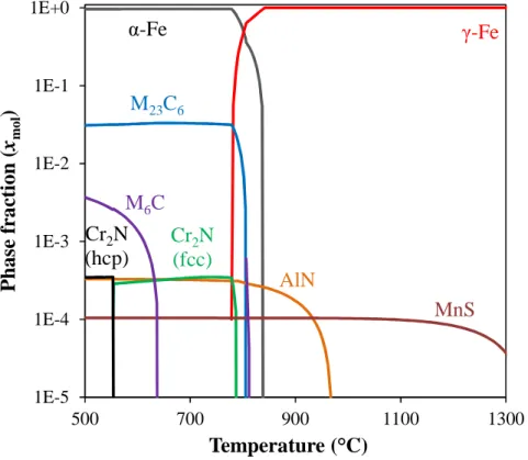
The nature of secondary phases and the ferrite-to-austenite transformation temperatures were investigated using two different softwares: MatCalc v. 6.00, using the mc_fe_v2.029 database (Figure 2.4); and ThermoCalc, using the TcFe7 database (Figure 2.5). The input chemical composition is that determined at the quarter-thickness and given in Table 2.1. Both simulations give similar results. However, one should notice that the ThermoCalc calculation tends to give higher dissolution temperatures for the secondary phases when compared to MatCalc, as detailed below.
The ferrite-to-austenite transformation is similarly described in both simulations: austenite starts to form at 778°C and 780°C respectively from ThermoCalc and MatCalc, and the transformation is fully finished respectively at 841°C and 830°C. Predicted equilibrium carbides are M23C6, which
dissolve in the intercritical temperature range, and M6C, which are stable up to 625°C. This is
consistent with literature data [14]. Predictions from both simulations are in good agreement with each other. The specific topic of carbide stability will be discussed in more detail in the chapter dedicated to precipitation (Chapter V).
Several other secondary phases coexist. AlN precipitates are well-known for pinning austenite grain boundaries during grain growth [38], and their actual effect will be discussed in Chapter III for the chemistry considered here. However, one should notice that MatCalc predicts dissolution of AlN at 930°C while ThermoCalc predicts it at 970°C.
Cr2N particles precipitate due to the excess of nitrogen in the material; this excess is due to the
low amount of aluminum. Interestingly, ThermoCalc calculations predict a change in crystallography from hexagonal to face-centered cubic structure for Cr2N at the vicinity of 550°C while MatCalc
calculations only show a stable face-centered cubic in the whole stability domain. However, these precipitates should not have any effect on the material properties: they cannot act as a pinning particles since they are not stable in the intercritical temperature range, and their overall phase fraction is low enough to be negligible in front of carbides for the study of the precipitation kinetics.
MnS particles are in very low concentration in the material (phase fraction of ~10-4). This type of particle is unavoidable in steels and appears during the steelmaking process. They are stable up to 1300°C, and will not play any role in the chemical evolution of the material. They are typically spherical particles, 1 µm in diameter, and can act as void nucleation sites in ductile fracture as shown in Figure 2.6.
As a conclusion, several equilibrium secondary phases are of interest in this material. AlN particles might play a role in the austenite grain growth, while MnS particles can have an effect on the mechanical properties by acting as void nucleation sites. Most important secondary phases are the carbides, which precipitation and transformation, before equilibrium is reached, have a great role in the material properties. This topic will be addressed in Chapter V.
![Figure 3.2: Schematic diagram of the interaction of a spherical particle with a moving grain boundary (from [51])](https://thumb-eu.123doks.com/thumbv2/123doknet/2995670.83997/53.892.290.617.393.723/figure-schematic-diagram-interaction-spherical-particle-moving-boundary.webp)