OATAO is an open access repository that collects the work of Toulouse
researchers and makes it freely available over the web where possible
Any correspondence concerning this service should be sent
to the repository administrator:
[email protected]
This is a
publisher’s version published in:
https://oatao.univ-toulouse.fr/26311
To cite this version:
Sun, Wei-Tsun and Jenn, Eric and Cassé, Hugues Validating Static
WCET Analysis: A Method and Its Application. (2019) In: 19th
International Workshop on Worst-Case Execution Time Analysis
(WCET 2019), 9 July 2019 (Stuttgart, Germany).
Official URL :
Validating Static WCET Analysis: A Method and
Its Application
Wei-Tsun Sun
IRT Saint Exupéry, Toulouse, France [email protected]
Eric Jenn
IRT Saint Exupéry, Toulouse, France Thales AVS, Toulouse, France [email protected]
Hugues Cassé
IRIT, Toulouse, France University of Toulouse, France [email protected]
Abstract
WCET analysis is a key activity in the development of safety critical real-time systems. Whether upper bounds on WCETs are obtained using static analysis or measurements, the confidence on the compliance of a system with its temporal requirements directly depends on the confidence on these estimations. Static WCET analysis based on abstract interpretation takes benefits from its formal foundations. However, it also strongly depends on the correctness of the underlying models. We hereby show how we have validated the version of the data flow static analyser of OTAWA applied to the AURIX TC275 target processor.
2012 ACM Subject Classification Computer systems organization → Real-time systems Keywords and phrases validation of WCET tools, ISS, nML
Digital Object Identifier 10.4230/OASIcs.WCET.2019.6
1
Introduction
In a real-time system, correctness in the time domain is as important as correctness in the value domain. For instance, a sensor value (resp. a message) may be meaningless if it is acquired (resp. delivered) too early or too late. For a software system, demonstration of temporal correctness relies on the estimation of the application’s Worst Case Execution Times (WCET).
WCET may be used to perform schedulability analysis or response time analysis, or to demonstrate compliance with the synchronous execution model hypothesis. WCET can be estimated empirically on the basis of measurements, or analytically on the basis of a model [19]. Among various WCET-estimation strategies, static WCET analysis relies on an appropriate abstraction of the application and execution platform to compute a safe upper bound of the actual WCET, by means of abstract interpretation [4].
Confidence on the results produced by static analysis directly depend on (1) the correctness on the processor model, and (2) the correctness of the analyses. In this paper, we present the method that we have used to validate these two elements for the Aurix TC275 static analyser for data flow. To ensure (1), we propose to compare the behaviour of an Instruction Set Simulator (ISS) generated from the processor model with a reference ISS or the actual platform. To ensure (2), we propose to compare the abstract states built by abstract interpretation with the concrete states generated from a reference ISS or the actual platform. Note that the proposed approach neither verifies all the analyses performed by the static
© Wei-Tsun Sun, Eric Jenn, and Hugues Cassé; licensed under Creative Commons License CC-BY
19th International Workshop on Worst-Case Execution Time Analysis (WCET 2019). Editor: Sebastian Altmeyer; Article No. 6; pp. 6:1–6:10
OpenAccess Series in Informatics
analyser, nor guarantees the absolute absence of errors for the analyses that are covered – it basically relies on testing –, but it does not require huge effort on modifying the existing framework, stays modular and can be automated.
This paper is organised as the follows: The background is presented in section 2; an overview of our approach is described in section 3; the application of our approach on the AURIX TC275 is detailed in section 4; the experimental results of the application are shown in section 5; the related and the on-going works are described in section 6; finally section 7 concludes the paper.
2
Background
This section introduces the OTAWA framework used to develop WCET static analysers, and the Sim-NML language used to describe ISA (Instruction Set Architectures).
2.1
OTAWA - an open source framework to compute WCET
OTAWA [3] is an open-source framework to build static WCET analysers. A typical WCET analyser is built on the following facilities provided by OTAWA: (1) the binary decoder used to extract the program instructions and other information contained in the executable file, such as the initial memory contents; (2) a set of static analyses based on abstract interpretation [4] to capture the behaviours of the underlying hardware; and (3) other components to aid the WCET computation, e.g. an ILP solver.
The binary decoder is generated by the the GLISS [13] tool from a description of the target processor’s ISA written in Sim-NML [18]. An ISS (instruction-set simulator) is also generated from the same description.
Being open-source and its implementation structure, the framework can be easily extended to provide new capabilities, including the generation of any intermediate result of the static analyses. For instance, to support the validation activities presented in this paper, it was modified to produce the concrete processor states from the customised- and generated-ISS, and the abstract states produced by the abstract analyser. The same strategy can be applied to any other open-source WCET computation framework.
2.2
Sim-NML: the language to describe ISA and semantic instructions
OTAWA is designed to be platform-independent. To achieve this independence, the model of the hardware target – including its ISA and the behaviour of its instructions – are described in an external file using the dedicated language Sim-NML.Listing 1 shows the mov instruction from the Tricore architecture described in Sim-NML. The first line declares that mov operates on two data registers (of type reg_d) named c and b. The second line describes the bit-level structure (or “image”) of the instruction: the first 4 bits contains the ID of the register c, followed by the 8-bit value 0x1F, and so forth. An “X” indicates an unused bit. The third line describe the syntax of the operation in assembly code. Finally, the action segment describes the behaviour of the instruction. In this example, it assigns the value of register b to register c. This segment is used to generate the ISS using GLISS2, and to perform some analyses such as program slicing (i.e. to propagate the register values, the analyser needs to identify the registers that are written/read).
In order to make static analysis as independent as possible from the target platform, OTAWA translates each instruction into a set of more primitive semantic instructions [2]. Those semantic instructions must capture the behaviours of all instructions encountered in an execution scenario.
W.-T. Sun, E. Jenn, and H. Cassé 6:3
Listing 1the structure of NMP that describes an instruction - mov.
op m o v _ r e g ( c : reg_d , b : r e g _ d )
i m a g e = f o r m a t ( " % 4 b %8 b X X X X %4 b X X X X %8 b " , c . image ,0 x1F , b . image ,0 x0B ) s y n t a x = f o r m a t (" mov % s ,% s " , c . syntax , b . s y n t a x )
a c t i o n = { c = b ; }
Listing 2Provide the instruction type as an attribution to the mov instruction.
e x t e n d m o v _ r e g
sem = { SET ( D ( c . i ) , D ( b . i )); }
Semantic instructions are added to the existing operation description as shown in Listing 2 using attributes. In this example, the semantics of mov is expressed using the SET semantic instruction; it states that register c shall get the value of register b. Note that the register naming follows the declaration of the original operation (as shown in the second line).
Currently, the descriptions for each instruction is still produced manually, and this can be an error-prone process. Errors may affect the selection of the registers (e.g., specifying register d as the target instead of register c) or the translation into the semantic instructions (which would not correctly capture the meaning of the processor instruction)1.
3
The proposed approach
Out of our experience, errors are essentially introduced (i) during the modelling of the processor’s ISA, and (ii) during the implementation of the static analysis based on abstract domains. To identify errors introduced in (i), we propose to cross-check the ISS (instruction-set simulator) provided by the manufacturer (or by any other trusted source) with the ISS generated from the processor ISA model in Sim-MNL. To identify errors introduced in (ii), we propose to cross-check the abstract states computed by the abstract interpreter against the concrete states computed by some trusted ISS or by the ISS generated out of the processor ISA model.
3.1
Verification of the processor ISA model
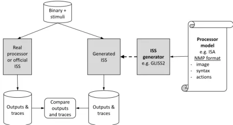
Figure 1 shows the different steps necessary to verify the processor ISA model. In our case, the model is crafted using the NMP format based on Sim-NML [18]. It is then fetched to an ISS generator, e.g. GLISS2 [13], to generate an ISS automatically.
The verification process consists of executing one or several test programs (with their stimuli) on both the real processor (or some trusted ISS, such as the Infineon’s TSIM for the TC275) and the generated ISS, and to compare the execution traces obtained from the two executions. Execution traces contain the successive states of the processor registers and the memory contents. If both traces are identical, the processor model and the actual processor are deemed equivalent (for the test programs considered). Otherwise, the execution traces are investigated to find the causes of the discrepancy(ies), and to correct the processor Sim-NML model. This is an iterative process that stops when equivalence is shown for all test programs.
1 An automatic translation from the behaviour description of an operation to semantic instructions is
relatively complex and not implemented in OTAWA: actual machine instructions are often very complex and provides much more details than required by dataflow analyses.
ISS generator e.g. GLISS2 Generated ISS Real processor or official ISS Binary + stimuli Processor model e.g. ISA NMP format - image - syntax - actions Outputs & traces Outputs & traces Compare outputs and traces
Figure 1Verification of the processor model.
3.2
Verification of the static analyser
Abstract interpretation proceeds by executing a program in an abstract domain that preserves the properties of interest. This interpretation relies on the semantics of the instructions given in the ISA model which verification has been described in the previous section.
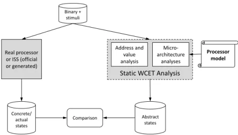
The static analysers interpret all the instructions of a given binary to determine the successive states of the execution platform components, including registers, memories, etc. To verify that the analysis is correct, we propose the approach depicted in Figure 2.
The program object code (binary) is processed by both the static analyser and the actual processor (or an ISS). They produce a series of abstract states and concrete states, respectively. Comparison between the two traces is performed at specific “comparison points” corresponding to specific program locations. Comparison can be done at “fine-grain” (e.g., at each instruction) or at “coarse-grain” (e.g., at the end of each function call). For each comparison point, the concrete state is checked against the corresponding abstract state. Abstraction is deemed correct if, for all comparison points, the abstract state is a correct abstraction of the corresponding concrete state. In Abstract Interpretation, an abstract state is sound at a particular program point if it includes any valid concrete state generated at this point. Note that, as for the previous verification, validity is demonstrated with respect to one or several input programs and on or several input stimuli for each program, so, the quality of the verification depends on the “coverage” of the program set and input stimuli.
4
Applying the proposed approach for support AURIX TC275 on
OTAWA
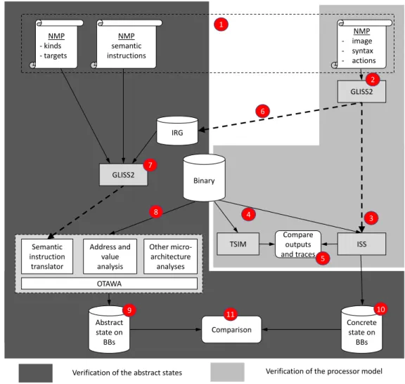
Applying the proposed method on the AURIX TC275 is illustrated in Figure 3, where each step of the method is numbered. The figure is partitioned into two parts: the light gray area covers the validation of the processor model, such as the instruction decoding and branch-target identification. The dark grey area covers the validation process for any static analysis used in the overall WCET estimation process.
W.-T. Sun, E. Jenn, and H. Cassé 6:5 Processor model Micro-architecture analyses Address and value analysis
Static WCET Analysis
Binary + stimuli Real processor or ISS (official or generated) Abstract states Concrete/ actual states Comparison
Figure 2Verification of abstract states versus the concrete states.
4.1
Verification of the TC275 processor ISA model
In the first phase, the NMP files are created (1) to capture the description of the ISA, which consists of the decoding information of the instructions as well as their behaviour (the semantic instructions) to enable architecture-independent static analyses. The content of the NMP files are created out of the documentation provided by the chip manufacturer. For the TC275, for instance, the instruction timings are extracted from the data-sheet [1] and the instruction formats and behaviours are obtained from the instruction-set user manual [17].
In the second phase, the GLISS2 tool uses the NMP files to generate a library for instruction decoding and a standalone ISS (3).
To validate the NMP model, a program binary is loaded and executed by both the generated ISS and a reference execution structure (simulator or actual processor). In our case, the reference is the TSIM ISS provided by Infineon (4). The two execution traces (i.e. the sequence of the instructions and their addresses, the register values, and the accessed memory content) are then compared (5). Any discrepancy found during the comparison shall lead to the correction of the ISA description and to a new iteration of the process.
4.2
Verification of the abstract interpreter for the TC275
A database of operations (IRG file) is generated by processing the ISA description using the GLISS2 tool (6). The semantic instructions are added to operations through the use of the
extend keyword (7) as presented in Section 2.2. The target binary file is then given as input
to OTAWA for WCET estimation (8).
As the first step of the WCET estimation, OTAWA processes the binary thanks to the instruction decoder provided with the ISS (see (3)). The structural elements of the program – the CFGs (control-flow graph) and BBs (basic blocks) – are also identified in this step. Then the corresponding semantic instructions are interpreted, the abstract states are computed and associated with each BB.
Finally, an ILP problem is created with an objective function composed from the results of the aforementioned analyses and the constraints from the program structure. The solution of the ILP problem determines the WCET.
Other micro-architecture analyses Semantic instruction translator Address and value analysis OTAWA GLISS2 ISS TSIM GLISS2 Binary IRG Abstract state on BBs Concrete state on BBs NMP semantic instructions NMP - kinds - targets NMP - image - syntax - actions 1 2 3 4 6 7 8 9 10
Verification of the abstract states Verification of the processor model Comparison
Compare outputs and traces 5
11
Figure 3The overall workflow that combines both validation approaches.
To validate the static analysis, the abstract states associated with each BB are extrac-ted (9). At each check point, e.g., the end of a BB, the concrete state (10) is compared with the abstract state (11). If the concrete state is part of the abstract state, then we consider that the verification has passed for this given binary. Verification shall be performed on several binaries to improve confidence. Similar to the verification process of the processor ISA model, the validation of the static analyser is also iterative: for any discrepancy detected, a correction is applied, and the verification process is performed again.
Address/value analysis in OTAWA uses the CLP abstract domain [15, 2]. As the CLP abstract domain is used for several subsequent analyses as data-cache analysis (to know which address the program tries to access), dynamic-branch resolution [16], etc., its soundness and precision is crucial for the WCET estimation. The CLP abstract states consist of the values of each register and each accessed memory location expressed in the CLP domain. The evolution of the abstract states are based on the interpretation of the semantic instructions of the given program.
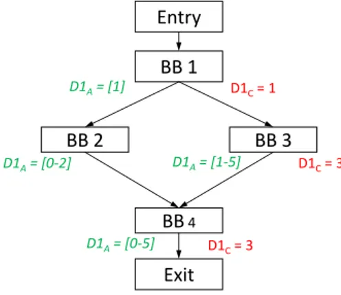
An example of verification is depicted on Figure 4. The target program consists of a single if-else statement. Abstract states (DA) are displayed at the end of each BB. Only the
W.-T. Sun, E. Jenn, and H. Cassé 6:7
is represented as a range. At the end of BB1, D1 contains value [1]. Since static analysis considers all possible scenarios, both execution paths to BB2 and BB3 are taken into account, which leads to two different abstract states: [0-2] at the end of BB2, and [1-5] at the end of BB3. These states are joined at the beginning of BB4. The resulting state is [0-5] which encompasses both ranges. As D1 is not modified in BB4, this is also the value of D1 at the end of the program.
The concrete states of D1 (i.e., the values computed during a concrete execution) are denoted by DC on the figure. Note that there is no concrete state associated with BB2
because only the right branch (leading to BB3) was executed during the test. Whenever the execution reaches the end of a BB, the current concrete state is compared with the corresponding abstract state, e.g. for BB 3, D1 = 3 which falls in the range [1-5], so the test passes. The validation of the address/data analyses provides two “guarantees”: (1) the correct translation of semantic instructions in the NMP file, and (2) the correct
abstract interpretation. BB 1 BB 2 BB 3 BB4 D1A= [1] D1A= [0-2] D1A= [1-5] D1A= [0-5] D1C= 1 D1C= 3 D1C= 3 Entry Exit
Figure 4An example of checking if the abstraction is satisfied.
5
Experiments and results
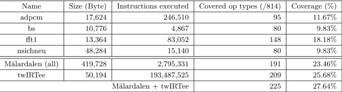
Our approach has been applied using two sets of input programs: a subset of the Mälardalen benchmarks suite [8], and the set of software components of our robotic demonstrator (TwIRTee). The coverage of the verification, expressed by the ratio between the number of different operations executed in the programs, and the number of possible operations s (i.e., all the combinations of the opcodes, operands, and addressing modes, described as different “op” in the NMP file). Due to the space limitation (35 benches from Mälardalen), partial
results are shown in Table 1.
There are 814 opcode-operand combinations (instruction types) in total for the TC1.6 (the CPU family used in TC275), As for any test-based verification approach, the test coverage – and so the confidence on the verification results – is highly dependant on the test inputs. In particular, the complexity and code size of an individual benchmark does not have direct relationship with the coverage (the number of different opcode-operand combination used). For instance, program adpcm is around one-third smaller than program nsichneu but it gives a higher coverage. Similarly, program bs executes around 3 times less instructions than
nsichneu, but gives a similar coverage. Moreover, all benchmarks share a common sequence
of instructions (the function _start which initialises the context area for function call and stack) which can represent a significant part of the instruction coverage of a simple program (this explains why the very simple binary-search application bs covers 80 combinations).
Mälardalen benchmarks cover 191 combinations (23.46%) while the TwIRTee robotics application alone covers 209 combinations (25.68%). This tends to show that using actual application code (involving a greater variety of algorithms) allow achieving a higher coverage level. Together, Mälardalen benchmarks and TwIRTee only cover 28.64% of all combinations. This may indicate that the compiler privileges a small set of opcode-operand combinations. This limit could be overcome by directly synthesising assembly code test programs.
Table 2 gives the number of errors found in the TC275 NMP files using our method. For each test, nearly 1/3 of the covered opcode-operand combinations were erroneous. Even though the ratio of errors are similar among the tests, errors are not correlated. Common errors are: (1) wrong bit-ordering, i.e. a bit range “m to n” is replaced by “n to m”, or an erroneous bit-index is used; (2) incorrect sign-ness; (3) register-type error, e.g. using a data register in place of an address register; and (4) mis-interpreting the ISA from the user manual. The mappings of the semantic instructions are prone to the following errors: (1) using the content of a register as a value rather than an index; (2) mis-interpreting the
behaviours of instructions.
Concerning the CLP analysis, few errors were detected, including one affecting the implementation of the widening operation between two specific CLP ranges: one “corner case” had not been considered. As a by-product of the validation process, some improvements of the accuracy of the analysis were also identified, when applying the fixes to the errors found, where the re-structuring of the existing codes. This includes the implementation of the bit-wise AND operation between two CLP values. For instance, applying a bit-wise AND with a range [-0xFF, 0xFF] and a constant 0xFF was producing the range [-0xFF, 0xFF]. While safe (i.e., all possible values were covered), this range contains negative values (sign-extended); after modification, the result is now [0, 0xFF].
Table 1Verification of the ISA through ISS executions.
Name Size (Byte) Instructions executed Covered op types (/814) Coverage (%)
adpcm 17,624 246,510 95 11.67% bs 10,776 4,867 80 9.83% fft1 13,364 83,052 148 18.18% nsichneu 48,284 15,140 80 9.83% Mälardalen (all) 419,728 2,795,331 191 23.46% twIRTee 50,194 193,487,525 209 25.68% Mälardalen + twIRTee 225 27.64%
Table 2Results of detection.
Type Error found (full / 814, tested)
ISA model 67 (8.2%, 29.8%)
W.-T. Sun, E. Jenn, and H. Cassé 6:9
6
Related and on-going works
The soundness verification of analyses involved in WCET calculation is a relatively old topic. In 2001, Ferdinand et al. [7] presents the main principles of their tool suite, named later
aiT, as being sound-by-construction. This claim concerns mainly the use of static analysis
applied to obtain the WCET and is supported (a) by a rich scientific amount of surveys devoted to the formal definition and verification of analyses based on Abstract Interpretation and (b) by the automatic generation of analyses using a tool named PAG. Yet, the authors admits that the architecture model, provided by hand, weakens the approach. More recently, [11] proposes a verified tool that is able to compute WCET using standard IPET method. The tool is embedded in CompCERT [10] but only targets high-level analyses – value, loop bounds and ILP generation, and the issue of hardware verification is not treated.
In [14], Schlickling et al. present an approach to derive a timing model2usable in a WCET
tool from a pipeline description in VHDL. The approach involves several passes of dead-code or useless code elimination combined with abstractions driven by human interaction. The approach is promising but (a) needs reduced but necessary human action and (b) requires the VHDL model of the pipeline. A similar approach might be applied to automatically extract semantics of instructions but we are not aware of any work in this direction.
There are alternatives to OTAWA’s semantic language. ALF [9] was designed as an independent language to represent semantics of binary programs. Although several translators from binaries to ALF exist, we are not aware of any work towards verification. CRL2 is used in aiT [6] to represent the program whatever the underlying machine code but very few information about it are available and specially about the support of instruction semantics. Currently the ISA model (used in instruction decoding) and the semantic instructions (used in the CLP analysis) are constructed separately. This prevents the bugs in the ISA model being entailed in the semantic instructions. The human-error is the main cause when creating both models, in particularly, i.e. two times of efforts are made to create models which are relevant. An on-going work is to create a single model (e.g. ISA) and then the mapping of semantic instructions will be performed automatically. To increase the coverage of our validation process, using benchmarks such as Papabench [12] and systematic constructed programs [5] is also under the investigation.
7
Conclusions
In this paper we have proposed and applied a method to verify some important components of a static WCET analyser: the ISA model and the associated semantic model used by the abstract interpreter, and some parts of the abstract interpreter itself. The verification process is achieved by cross-checking the result produced by a reference implementation of the target processor (a simulator or the actual hardware) and some intermediate results produced by the WCET analysis tool. This approach has been applied on the WCET analyser for the TC275 processor implemented using OTAWA and leads to the detection of numerous errors in the TC275 ISA model and associated semantic model, and a few errors in the abstract interpreter.
2 The obtained timing model is mainly an abstract simulator of the microprocessor states.
References
1 AURIX TC27x D-Step 32-Bit Single-Chip Microcontroller User’s Manual V2.2 2014-12. 2 Hugues Cassé, Florian Birée, and Pascal Sainrat. Multi-architecture value analysis for machine
code. In 13th International Workshop on Worst-Case Execution Time Analysis, pages pp–42, 2013.
3 Hugues Cassé and Pascal Sainrat. OTAWA, a framework for experimenting WCET
computa-tions. In 3rd European Congress on Embedded Real-Time Software, volume 1, 2006.
4 Patrick Cousot and Radhia Cousot. Abstract interpretation: a unified lattice model for static
analysis of programs by construction or approximation of fixpoints. In Proceedings of the 4th
ACM symposium on Principles of programming languages, pages 238–252, 1977.
5 Thanh Nga Dang, Abhik Roychoudhury, Tulika Mitra, and Prabhat Mishra. Generating
test programs to cover pipeline interactions. In 2009 46th ACM/IEEE Design Automation
Conference, pages 142–147. IEEE, 2009.
6 Christian Ferdinand and Reinhold Heckmann. ait: Worst-case execution time prediction by
static program analysis. In Building the Information Society, pages 377–383. Springer, 2004.
7 Christian Ferdinand, Reinhold Heckmann, Marc Langenbach, Florian Martin, Michael Schmidt,
Henrik Theiling, Stephan Thesing, and Reinhard Wilhelm. Reliable and precise WCET determination for a real-life processor. In International Workshop on Embedded Software, page 469–485. Springer, 2001.
8 Jan Gustafsson, Adam Betts, Andreas Ermedahl, and Björn Lisper. The Mälardalen WCET
benchmarks: Past, present and future. In 10th International Workshop on Worst-Case
Execution Time Analysis. Schloss Dagstuhl-Leibniz-Zentrum fuer Informatik, 2010.
9 Jan Gustafsson, Andreas Ermedahl, Björn Lisper, Christer Sandberg, and Linus Källberg.
ALF-a language for WCET flow analysis. In 9th International Workshop on Worst-Case
Execution Time Analysis (WCET’09). Schloss Dagstuhl-Leibniz-Zentrum für Informatik, 2009.
10 Xavier Leroy et al. The CompCert verified compiler. Documentation and user’s manual.
INRIA Paris-Rocquencourt, 53, 2012.
11 André Maroneze, Sandrine Blazy, David Pichardie, and Isabelle Puaut. A formally verified
WCET estimation tool. In 14th International Workshop on Worst-Case Execution Time
Analysis. Schloss Dagstuhl-Leibniz-Zentrum fuer Informatik, 2014.
12 Fadia Nemer, Hugues Cassé, Pascal Sainrat, Jean-Paul Bahsoun, and Marianne De Michiel.
Papabench: a free real-time benchmark. In 6th International Workshop on Worst-Case
Execution Time Analysis (WCET’06). Schloss Dagstuhl-Leibniz-Zentrum für Informatik, 2006.
13 Tahiry Ratsiambahotra, Hugues Cassé, and Pascal Sainrat. A versatile generator of instruction
set simulators and disassemblers. In 2009 International Symposium on Performance Evaluation
of Computer & Telecommunication Systems, volume 41, pages 65–72. IEEE, 2009.
14 Marc Schlickling and Markus Pister. Semi-automatic derivation of timing models for WCET
analysis. In ACM Sigplan Notices, volume 45, 4, pages 67–76. ACM, 2010.
15 Rathijit Sen and YN Srikant. Executable analysis with circular linear progressions. Technical
report, Technical Report IISc-CSA-TR-2007-3, Computer Science and Automation Indian . . . , 2007.
16 Wei-Tsun Sun and Hugues Cassé. Dynamic branch resolution based on combined static
analyses. In 16th International Workshop on Worst-Case Execution Time Analysis-WCET
2016. OASICs, Dagstuhl Publishing, 2016.
17 TriCore™ TriCore™ V1.6 Microcontrollers User Manual (Volume 2).
18 Johan Van Praet, Dirk Lanneer, Werner Geurts, and Gert Goossens. nML: A structural
processor modeling language for retargetable compilation and ASIP design. In Processor
Description Languages, pages 65–93. Elsevier, 2008.
19 Reinhard Wilhelm, Jakob Engblom, Andreas Ermedahl, Niklas Holsti, Stephan Thesing, David
Whalley, Guillem Bernat, Christian Ferdinand, Reinhold Heckmann, Tulika Mitra, et al. The worst-case execution-time problem—overview of methods and survey of tools. ACM