Open Archive TOULOUSE Archive Ouverte (OATAO)
OATAO is an open access repository that collects the work of Toulouse researchers and
makes it freely available over the web where possible.
This is an author-deposited version published in :
http://oatao.univ-toulouse.fr/
Eprints ID : 18108
To link to this article : DOI:
10.1016/j.surfcoat.2016.08.059
URL :
http://dx.doi.org/10.1016/j.surfcoat.2016.08.059
To cite this version :
Texier, Damien and Monceau, Daniel and
Hervier, Z. and Andrieu, Eric Effect of interdiffusion on mechanical
and thermal expansion properties at high temperature of a MCrAlY
coated Ni-based superalloy. (2016) Surface and Coatings
Technology, vol. 307 (Part A). pp. 81-90. ISSN 0257-8972
Any correspondence concerning this service should be sent to the repository
administrator:
[email protected]
Effect of interdiffusion on mechanical and thermal expansion properties
at high temperature of a MCrAlY coated Ni-based superalloy
D. Texier
a,b,⁎
, D. Monceau
a, Z. Hervier
c, E. Andrieu
aaCIRIMAT, ENSIACET-INPT, 4, allée Emile Monso, BP 44362, F-31030 Toulouse Cedex4, France
bMechanical Engineering Department, Ecole de Technologie Supérieure, 1100 Rue Notre-Dame Ouest, Montréal H3C 1K3, Québec, Canada cMaterials, Processes and Investigations Department, Safran Helicopter Engine, Avenue Joseph Szydlowski, 64510 Bordes, France
a b s t r a c t
Free-standing microtensile specimens were extracted from the substrate and the interdiffusion zone of a MCrAlY coated nickel-based single-crystal superalloy. Testing of these specimens was conducted at elevated tempera-tures, up to 1100 °C under controlled atmosphere, to assess the tensile and thermal expansion properties of the interdiffusion zone materials. These properties were measured and found to lie between the properties of the substrate and those of the coating. The poor mechanical strength of the interdiffusion zone evidenced its non-load bearing contribution to the system for uniaxial creep loading at high temperature representative of ser-vice conditions. It was also shown that the fabrication process of MCrAlY coated nickel-based superalloy affects the mechanical properties of the system due to the presence of voids and non-adherent grit-blasting particles within the interdiffusion zone.
Keywords: Ni-based superalloy MCrAlY coating Interdiffusion Micromechanics Tensile test High temperature 1. Introduction
Gas turbine blades undergo severe service conditions with high me-chanical and thermal loadings under aggressive atmospheres. The chemical composition and the microstructure of Ni-based single crystal superalloys have been optimized through different generations to resist creep deformation at high temperature[1,2]. To protect these materials from environmental degradations, i.e. isothermal and cyclic oxidation at high temperature and intermediate temperature corrosion, blades are generally coated. However, both the coating process and the heat treat-ments associated to the “as received” microstructure favor the interdif-fusion between the coating and the superalloy[3]. Consequently, an interdiffusion zone forms into the superalloy inducing a complex multi-layer material. The microstructure of each multi-layer evolves under service conditions due to the combined effect of high temperature and mechan-ical stresses. The variation of the chemmechan-ical composition in the different zones may affect their coefficient of thermal expansion. Composition evolution also modifies the lattice parameters of the γ and γ′ phases in the superalloy and therefore affects its microstructure and mechani-cal properties. Such microstructure modifications are expected to affect locally the creep resistance for which the superalloy was originally
designed[4,5]. When designing engine parts, the coating can be ac-knowledged as weak compared to the superalloy substrate, and can therefore be considered as a peripheral non-load bearing zone. Because its properties are unknown, the interdiffusion layer can also be consid-ered as a non-load bearing zone whose thickness is time and tempera-ture dependent [6,7]. This last consideration is based on the comparison of steady-state creep rates and lifetimes of thin-walled coating specimens and bulk specimens. Such a design rule can be used as a first approximation for thin-walled coated structural parts. Howev-er, more advanced predictive models of the mechanical behavior of these coated materials, used for lifetime assessment, require databases of material properties for each layer affected by the interdiffusion. Bensch et al. investigated the effects of oxidation-induced chemical composition changes on the creep properties of single crystal Ni-based superalloys at elevated temperature[4,5,8,9]. They used alloys with chemical compositions matching those of superalloys after oxidation. In the present paper, effects of interdiffusion and coating were investi-gated using micrometric specimens extracted from real coated systems. These micrometric thick specimens were tested at temperatures repre-sentative of service conditions. In the literature, previous studies report several attempts to assess the micromechanical behavior of materials at high temperature, especially for coatings. Micro-indentation [10], micro-tensile[11–13], micro-pillar compression[14], shearing[15]or punch tests[16]were used to assess local mechanical properties of bond-coated superalloys. However, the mechanical strength and the
⁎ Corresponding author at: Ecole de Technologie Supérieure, 1100 Rue Notre-Dame Ouest, Montréal H3C 1K3, Québec, Canada.
E-mail address:[email protected](D. Texier).
thermal expansion properties of the substrate affected by the cross-dif-fusion with the coating, i.e. the interdifcross-dif-fusion zone, need further documentations.
The present study characterizes, at a local scale, the tensile and the thermal expansion behavior of each zone constituting the multilayer system using specific mechanical test rigs developed for this purpose
[17–19].
2. Materials and experimental approach 2.1. Materials
The system studied is a MC2 first generation single-crystal Ni-based superalloy[20]coated with a 70 μm thick NiCoCrAlYTa layer produced by TRIBOMET© electrochemical deposition[21]. This deposition process consists of an electro-deposition of CrAlYTa particles entrapped in a Ni,Co matrix.
The MC2 rod was solidified by a withdrawal process along the [001] crystallographic direction and was submitted to a 3 h–1300 °C solution heat treatment. The nominal composition (at.%) of the Ni-based single crystal superalloy was Ni–8.9Cr–5.1Co–1.3Mo–2.5W–10.7A1–1.8Ti– 2.0Ta. Plates were machined from the rod (width and thickness coinci-dent with secondary dendritic arms directions and length aligned with primary dendritic arms — orientation within 7° off [001]) and grit-blast-ed before coating. The mean chemical composition (at.%) of the coating measured by quantitative EDX analysis was Ni–19.8Cr–17.2Co–0.2Mo– 0.5W–17.2A1–0.1Ti–1.3Ta–0.8Y. Aging heat treatments (1080 °C– 6 h + air cooling followed by 870 °C–20 h + air cooling) were finally conducted to ensure the optimization of creep microstructure of the su-peralloy and the chemical anchorage of the layers through interdiffu-sion. Three layers are commonly observed (Fig. 1): the monocrystalline substrate (S.Z.), the coated zone (C.Z.) and the interdif-fusion zone (ID.Z.).
2.2. Characterization techniques
Specimens dedicated for observation were polished to 1 μm using di-amond paste. To reveal the γ/γ′ microstructure, an electrolytic etching with 13 vol.% H3PO4, 45 vol.% H2SO4and 42 vol.% HNO3was carried
out under 5 V to preferentially consume the γ phase. Microstructure analyses were conducted using a LEO435VP scanning electron micro-scope (SEM) operating at an accelerating tension of 15 kV. The emission current was 150 pA and 2500 pA for secondary electron (SEI) and backscattered electron (BSE) observations, respectively. EDX analyses were performed on a full system's cross sections with a JEOL JSM6400
SEM equipped with an Oxford EDAX analyzer. Probe current was first measured through a Faraday cage in order to guarantee 1.5 nA. The cal-ibration of each constituent was carried out on real standards. Composi-tion profile was quantified by averaging EDX signal on 5 × 200 μm2
boxes to include the different representative microstructural features. 2.3. Mechanical characterization
2.3.1. Specimen preparation
Free-standing specimens have been extracted from the coated su-peralloy system to characterize the mechanical properties at the elevat-ed temperature of the monocrystalline substrate, the coatelevat-ed zone and the interdiffusion zone. Thirty-five-millimeter-long and 2-mm-wide ribbon shape specimens were first machined out with a STRUERS Secotom-50 high-precision cutting machine from the coated superalloy system. The longitudinal direction of the ribbon shape specimen was aligned with the withdrawal direction of the monocrystalline superal-loy. Substrate (S.Z.) and interdiffusion zone (ID.Z.) specimens were pre-pared using a LOGITECH CL50 lapping machine associated with a PP5GT precision Jig, limiting the effect of grinding on the residual stresses and ensuring flatness of the specimens. Incremental polishing combined with microscope observations were used for the positioning at the orig-inal coating/surface interface in the case of ID.Z. specimens. The varia-tion in thickness along the gage length is smaller than ± 0.5 μm. The complete procedure of specimen preparation is detailed in refs.[17, 18]. Substrate and interdiffusion zone specimen thicknesses were rang-ing from 124 to 130 μm and 37 to 39 μm, respectively.
2.3.2. High temperature tensile tests under controlled atmosphere Dedicated test rigs have been recently developed to perform me-chanical tests at elevated temperature under controlled atmosphere on ultrathin specimens[17,18]. Specimens were gripped in self-tighten-ing miniature grips. Tensile experiments were conducted under dis-placement control for an equivalent strain rate of 5 × 10⁻⁵s−1.
Because of the small thickness of the specimens, the macroscopic strain was calculated from the measurement of grip displacement, performed with a KEYENCE LS7030M optical micrometer. Temperature measure-ments were carried out at two locations with very thin S-type thermo-couples (76 μm diameter) spot-welded on platinum plates (90 μm thickness), located close to the gage length. Due to the very high sur-face/volume ratio of ultrathin specimens, surface degradation might considerably affect the mechanical properties of the material investigat-ed. Environmental conditions were hence optimized to avoid surface degradations during mechanical testing such as oxidation or metal sub-limation. Mechanical tests were conducted under a 120 kPa high purity
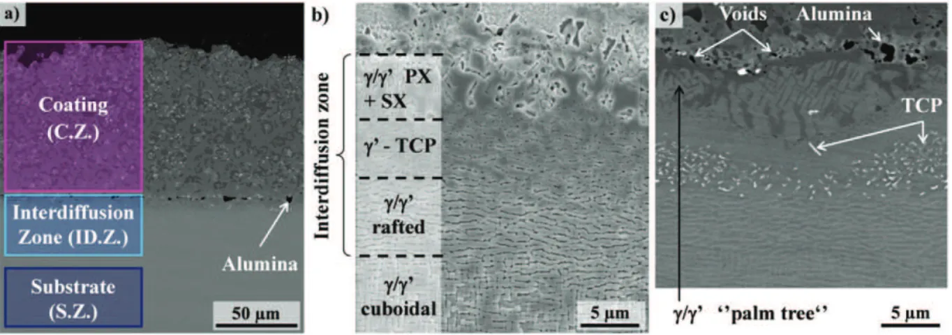
Fig. 1. a) General view of the gradient of microstructure of a NiCoCrAlYTa coated MC2 superalloy (BSE-SEM). Magnifications of the interdiffusion zone (ID.Z.): b) SEI-SEM observation of an etched specimen, c) BSE-SEM observation. The thickness and the extraction location of the ID.Z. specimen tested in the present study are illustrated as the blue rectangle in Fig. 1a.
Ar static atmosphere combined with an oxygen getter made of particles of Zr to reduce the residual partial pressure of oxygen within the closed vessel. The present controlled atmosphere was demonstrated to greatly limit oxidation and sublimation of α-alumina-forming alloys at 1100 °C for tens of hours. Both the mechanical test rig and the testing procedure are fully detailed in refs.[17,18].
2.3.3. Thermal expansion measurements
Thermal expansion measurements of S.Z. and ID.Z. free-standing specimens have been conducted on the mechanical test rig detailed in
Section 2.3.2and in refs.[17,18]under controlled atmosphere. Dimen-sional variations of S.Z. and ID.Z. specimens were continuously mea-sured with a KEYENCE LS7030M optical micrometer for a constant heating rate of 0.5 K·s−1. A constant tensile load (1.5 N) was monitored
to ensure alignment of the specimen and the load trail. Blank measure-ments were previously performed for this heating rate in order to cor-rect the thermal dimensional variation due to grip expansion. 3. Results
3.1. Material characterization of the interdiffusion zone
The microstructure of the interdiffusion zone is the result of the dif-fusion of chemical elements between the coating and the substrate dur-ing the agdur-ing heat treatments (Fig. 1b and c). In this study, a particular interest was put into the inner part of the interdiffusion zone, which is the zone of the superalloy affected by the presence of the coating. This zone is delimited by alumina particles coming from grit-blasting (black particles observed with the backscattered electron mode in the SEM inFig. 1a and c). Indeed, these alumina particles are located at the initial position of the substrate-coating interface. (Ta,Ti)C precipi-tates (white particles inFig. 1a and c) are exclusively located in the coat-ing. They are formed by the reaction between fast diffusing carbon coming from the superalloy, Ta from the coating, and some Ti diffusing from the superalloy. These particles can help with the identification of the interdiffusion zone. A γ/γ′ “palm tree”-like microstructure, due to the cellular recrystallization favored by residual stresses induced by grit blasting, appears below these particles and precipitates (Fig. 1c). This polycrystalline area (PX) grows during the aging heat treatment at 1080 °C[22]. Additionally, a γ/γ′ layer is observed, it delimits both the zone of cellular recrystallization and the γ′ layer “peppered” with TCP (topologically close-packed) phases (see white precipitates shown inFig. 1c). Finally, a γ/γ′ rafted microstructure, parallel to the coating–substrate interface, can be observed (denoted “γ/γ′ rafted” in
Fig. 1b). This phenomenon is induced by a residual bi-axial compressive state in the substrate prior to the coating deposit associated with grit-blasting[22]. The P-type rafting induced by the heat treatment at 1080 °C is in accordance with the negative misfit existing between γ and γ′ phases at this temperature. The well-known cuboidal γ/γ′ micro-structure of SX Ni-based superalloys marks the end of the interdiffusion zone. This multilayered microstructure extends over 20 μm in depth into the superalloy for the “as received” system, that is after the com-mon heat treatment used for such engine parts.
The chemical composition profile from the coating to the substrate is given inFig. 2. The gradient of chemical composition extends on both sides of the original interface affecting both the coating and the superal-loy. Interestingly, tantalum and tungsten are segregated. The former is found at the interface due to (Ta,Ti)C precipitation and the latter at the diffusion front, inside the substrate, where TCP phases were formed. The diffusion front is located at the transition depth between the TCP re-gion and the P-type rafted microstructure. Therefore, the P-type rafting cannot be attributed to any chemical composition modification affecting the lattice misfit between γ′ precipitates and the surrounding γ matrix. This confirms that P-type rafting is due to residual compressive stresses from the grit-blasting process.
3.2. Effect of preparation on ID.Z. specimens
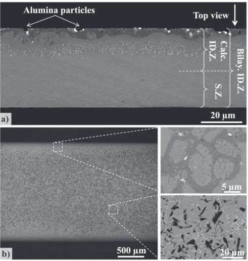
Specimen preparation has a strong impact on the reliability of the mechanical characterization, especially for specimens extracted from the interdiffusion zone. The interdiffusion zone presented a multilay-ered microstructure. Thus, proper attention has been paid to control the thickness and the extraction location of ID.Z. specimens within the multilayer system.Fig. 3highlights the accuracy of the extraction proce-dure.Fig. 3a and b respectively represent the cross-section and the top view of a specimen extracted from the interdiffusion zone. Cross-sec-tion observaCross-sec-tions of interdiffusion-zone specimens enabled an addiCross-sec-tion- addition-al verification of the ID.Z. specimens' thickness (ranging from 37 to 39 μm for the interdiffusion zone) and their exact extraction location. The original interface between the coating and the superalloy was “pep-pered” with alumina particles coming from grit-blasting of the substrate prior to the deposition process. Grit-blasting particles can be observed both on the top view and on the cross section of the specimen (see black particles inFig. 3).Fig. 3b shows that most of the specimen surface is located at the interface (area “peppered” with alumina) and that edges of specimens are blunted on 150 μm with a maximal depth of 4 μm at the extremity. For each specimen, the SEM observation of the surface provides enough information to estimate the surface area cov-ered by the “interface region”. It was found that 70 to 85% of the surface
area is covered by an “interface region”. The rest corresponds to the “cel-lular recrystallization” zone.
ID.Z. specimens were 37–39 μm thick whereas the thickness of the affected microstructure of the superalloy did not exceed 20 μm. Conse-quently, ID.Z. specimens are made of a significant fraction of superalloy base material, that is 46 to 49% in area fraction measured with cross-sec-tion SEM observacross-sec-tions. A bilayer approach was then used to estimate the tensile behavior of the interdiffusion zone. The bilayered ID.Z.
specimens and the calculated ID.Z. material were denoted “bilay. ID.Z.” and “calc. ID.Z.”, respectively. These denominations are reported inFig. 3a.
3.3. Tensile behavior
Tensile tests were conducted on S.Z. specimens and free-standing bilayered ID.Z. specimens at 950 °C, 1050 °C and 1100 °C.Fig. 4a and b
Fig. 3. a) Cross section of an ID.Z. specimen (BSE-SEM). b) Top view of an ID.Z. specimen (BSE-SEM). Magnifications on the grit-blasted “interface” (bottom) and on the cellular recrystallization region (top).
present stress–strain curves associated with each kind of specimen. Both the 0.2% offset yield strength (Y.S.) and ultimate tensile strength (U.T.S.) of each layer decreased with the temperature in the investigat-ed temperature range. The mechanical strength (Y.S. and U.T.S.) of both S.Z. and ID.Z. specimens are given according to the temperature inFig. 5. The tensile strength of S.Z. specimens were compared with bulk speci-men results reported in the literature, depicted as colored domains in
Fig. 5 [23]. Tests on bulk MC2 specimen were performed at two strain rates: 1 × 10⁻⁵s−1(bottom limit of each colored domain) and
1 × 10⁻⁴s−1(top limit)[23]. S.Z. specimens were found to have a
com-parable Y.S. but a slightly lower U.T.S. than bulk specimens. To the au-thors' knowledge, no tensile properties of such an interdiffusion zone have been reported in the literature.
Compared to the superalloy base material, the observed interdiffu-sion zone presents a lower mechanical resistance for the investigated temperature range, i.e. 0.2% yield strength (Y.S.), ultimate tensile strength (U.T.S.) and ductility. Concerning the tensile behavior of the bilayered ID.Z., an isostrain model approach (Voigt analytical model) has then been used to estimate the mechanical properties of this 20 μm thick affected zone (calc. ID.Z. inFig. 3a). Assuming the continuity of the deformation in both layers, stress within the interdiffusion zone is estimated with Eq.(1).
σCalc:ID:Z:ð Þ ¼ σε ! Bilay:ID:Z:ð Þ $ Sε Bilay:ID:Z:−σS:Z:ð Þ $ Sε S:Z:
"=SID:Z: ð1Þ
σi(ε) and Siare respectively the homogeneous stress in the layer i at
a given strain and the section of the material i. The tensile strength (Y.S. and U.T.S.) of calc. ID.Z. is reported inFig. 5as gray solid and dashed lines. Since the substrate exhibits a higher tensile strength in this range of temperature than the bilayered ID.Z. specimen, calc. ID.Z. (gray solid and dashed lines) subsequently demonstrates lower tensile strength than the bilayered ID.Z. specimen (blue solid and dashed lines). These properties are reported inTable 1.
The tensile properties of the superalloy obtained from tensile testing on S.Z. specimens are used as a reference for 2D and 3D finite element (FEA) calculations. The FEA calculations were performed with ABAQUS 6.13 for comparison with the isostrain analytical model. CPE4R
rectangular elements and C3D8R parallelepiped elements were chosen to mesh the bilayer system for the 2D and 3D calculations, respectively. The substrate/interdiffusion zone thickness ratio was respected for each specimen. Isotropic elastic and plastic tensile behaviors were chosen for the interdiffusion zone (isostrain calculation from the ID.Z. specimen) and the substrate (experimental data from the S.Z. specimen) for each temperature. The occurrence of grit-blasting particles and voids was not taken into account in the FEA calculations. Due to symmetries of the system, only a quarter of the specimen was modeled and symmetry conditions were applied. Incremental displacements of the nodes at the extremity of the specimen were imposed in order to achieve 5 × 10⁻⁴
total strain between each step. The macroscopic stress was considered as the average value of the principal longitudinal stresses S11at the
dif-ferent nodes of the mid-specimen section normal to the loading direc-tion. The calculated stress–strain curves of the bilayer specimen at 950 °C are plotted inFig. 6. No significant differences were found be-tween the three calculation methods for the different temperatures (b4 MPa at 950 °C). The estimated tensile properties (isostrain model) of the interdiffusion zone are reported inFig. 5andTable 1and com-pared with the tensile behavior of the bilayered interdiffusion zone and the superalloy. In comparison with the superalloy, a drop on the yield stress of the interdiffusion zone (Calc. ID.Z.) of about 155 MPa is observed in the investigated temperature range.
3.4. Thermal expansion properties of the different layers
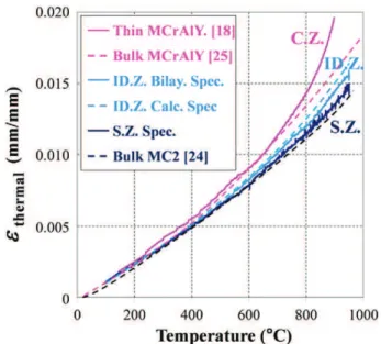
Thermal expansion measurements were conducted on S.Z. and ID.Z. specimens from room temperature to 1000 °C.Fig. 7presents the in-stantaneous thermal expansion of these materials according to the tem-perature. The thermal expansion of a bulk MC2 specimen[24]has been plotted as a black dashed line inFig. 7and is consistent with the one ob-tained for the ultrathin S.Z. specimen. The bilayered interdiffusion spec-imen exhibits a higher thermal expansion than the superalloy base material. A bilayer approach was used to estimate the thermal expan-sion of the interdiffuexpan-sion zone (Eq.(2)), assuming that no bending oc-curs during the thermal expansion experiment due to the 1.5 N load applied. αCalc:ID:Z:ð Þ ¼T εBilay:ID:Z:ð ÞT ∆T þ εBilay:ID:Z:ð Þ−αT S:Z:ð Þ $ ∆TT ! "$ES:Z:ð Þ$ST S:Z: ECalc:ID:Z:ð Þ$ST ID:Z:$ ∆T ð2Þ
αi(Τ), εi(Τ), Eiand Siare respectively the thermal expansion, the total
strain, the Young modulus and the section of the material i. The corrected interdiffusion (Calc. ID.Z.) thermal expansion is plotted in
Fig. 7using a blue dashed line. The thermal expansion of the calculated interdiffusion zone is higher than the thermal expansion of the superal-loy and of the bilayered interdiffusion zone. The thermal expansion of the NiCoCrAlYTa coating is reported inFig. 7for direct comparison (pink dashed line for a bulk NiCoCrAlYTa specimen[25]and pink solid line for a free-standing thin NiCoCrAlYTa specimen obtained with the present technique[18]). Results indicate that the interdiffusion zone has intermediate thermal expansion properties between the coating and the superalloy.
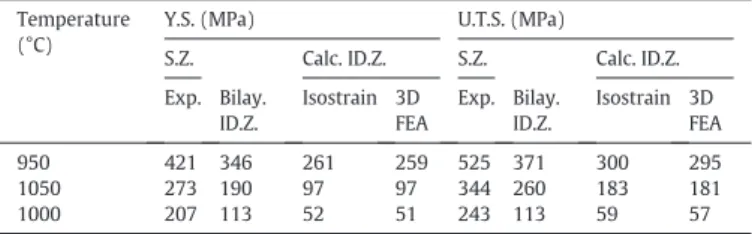
Fig. 5. 0.2% offset yield strength (Y.S.) and ultimate tensile strength (U.T.S.) of S.Z. specimens, bilayer ID.Z. specimens and calculated ID.Z. specimens as a function of temperature. Comparison with MC2 tensile behavior obtained on bulk specimens for strain rates of 1 × 10⁻⁵s−1(lower limit of the colored domains) and 1 × 10⁻⁴s−1 (lower limit of the colored domains)[23].
Table 1
Tensile properties (yield strength (Y.S.) and ultimate tensile strength (U.T.S.)) of the dif-ferent layers as a function of temperature.
Temperature (°C)
Y.S. (MPa) U.T.S. (MPa)
S.Z. Calc. ID.Z. S.Z. Calc. ID.Z. Exp. Bilay. ID.Z. Isostrain 3D FEA Exp. Bilay. ID.Z. Isostrain 3D FEA 950 421 346 261 259 525 371 300 295 1050 273 190 97 97 344 260 183 181 1000 207 113 52 51 243 113 59 57
The average linear coefficients of thermal expansion (CTE) were cal-culated from the instantaneous thermal expansion measurements and reported inTable 2. The CTEs of the interdiffusion zone and of the super-alloy base material increase with the temperature. Our results are con-sistent with the literature that reports higher CTE for coatings than for superalloys[24–29].
3.5. Fracture area
Low and high magnification SEM observations were performed after failure.Fig. 8presents fracture surfaces for S.Z. and ID.Z. specimens after tensile testing at 1050 °C. Despite the high length and width of the spec-imens when compared to their thickness, no twisting of the specspec-imens was observed for a homogeneous S.Z. specimen (Fig. 8a). Twisting was encountered for ID.Z. specimens presenting a gradient of microstructure and chemical composition through the thickness (Fig. 8d). In addition, S.Z. and ID.Z. specimen fracture surfaces exhibited areas where the
necking occurred along the entire surface and areas where slightly de-formed pores were observed (see e.g.Fig. 8b and e). As depicted in
Fig. 8a and d, the ID.Z. specimen displays a higher fraction of pores than the S.Z. specimen. Pores locations are shown with arrows inFig. 8d. Three to five pores were noticed on the fracture areas of the S.Z. specimen when more than thirty pores where observed on the fracture surface of the ID.Z. specimen.
4. Discussion
4.1. Thermal expansion and tensile behaviors of the interdiffusion zone Results indicate that tensile and thermal expansion behaviors of the superalloy base material underneath the coating/substrate interface are affected by interdiffusion and the deposition process. A significant drop in yield stress of the interdiffusion zone was noticed for the investigated temperature range in comparison with the ones of the superalloy. This decrease in yield stress can be the result of microstructural evolutions within the interdiffusion due to the contribution of both the fabrication process and the diffusion of chemical elements between the coating and the superalloy. The microstructure within the interdiffusion zone con-sists of a polycrystalline microstructure with a non-γ/γ′ strengthening layer and with the occurrence of TCP phases. It differs from the opti-mized cuboidal γ/γ′ single crystal microstructure of the base superalloy. In addition, both the tensile and the thermal expansion properties of the NiCoCrAlYTa coating used in the present study were recently
Fig. 6. a) Stress–strain behavior of the bilayered ID.Z. specimen at 950 °C calculated with 2D and 3D finite element analyses compared with experimental data. b) Slight differences in stress–strain curves in the high-stress regime of the bilayered ID.Z. specimen at 950 °C calculated with 2D and 3D FEA and compared with experimental data. The serration observed on the experimental plot is due to non-filtered dimensional measurements and the resolution of the load-cell measurements.
Fig. 7. Thermal expansion of S.Z. specimens, bilayer ID.Z. specimens (solid line) and calculated ID.Z. specimens (blue dashed line) as a function of temperature. Comparison with thermal expansion behavior of MCrAlY (pink solid line from ref.[18]for thin free-standing specimen and pink dashed line from ref.[25]for bulk specimen) and MC2 (black dashed line from ref.[24]) obtained on bulk specimens.
Table 2
Coefficients of thermal expansion of the different layers as a function of temperature. Temperature (°C) α (10−6°C−1)
S.Z. Bilay. ID.Z. Calc. ID.Z. C.Z.
[25–600] 13.5 13.9 14.3 15.1
700 14.3 14.6 15.5 16.2
800 14.8 15.3 16.3 17.9
900 15.4 16.0 17.3 22.0
characterized at high temperatures[18]. The interdiffusion zone thus exhibits intermediate tensile and thermal expansion behaviors with properties lying between those of the coating and those of superalloy above 950 °C. Those intermediate mechanical and thermal expansion behaviors found for the interdiffusion zone may help to assess if this zone can accommodate the different strains of the superalloy and its coating under the combined effects of thermal cycling stresses and ap-plied load. Thermal cycling stresses are mostly encountered in turbine blade service conditions, especially for helicopter applications where operation cycles are relatively short.
The low value of yield stress encountered at high temperature for the interdiffusion zone is below the level of stresses experienced on a real turbine blade. While no creep tests were performed on the interdif-fusion zone in the present work, the present tensile results may high-light the poor mechanical strength of the interdiffusion zone in comparison to the superalloy. Due to orders of magnitude between the strain rate during tensile tests and the one of airfoil blades during service ( _εtensileN104$ _εairfoilcreep), the interdiffusion zone is strongly
be-lieved to be a non-load bearing zone in conditions of low stress/high temperature creep. This experimental result confirms the necessity to calculate the “effective stress” after observation of the interdiffusion zone when dealing with mechanical tests performed on coated superal-loys[30]. This “effective stress” approach, generally admitted for coat-ings, was used in models through macroscopic experiments for the design of thin walled airfoil blades[6,7].
As depicted inFig. 8a and d, a curvature of ID.Z. specimens was ob-served after fracture while S.Z. specimens remained flat. ID.Z. and S.Z. specimens were flat before testing. The curvature of the ID.Z. specimens results from a lengthening of the interdiffusion zone along the width of the specimen in comparison with the superalloy. Close to the fracture area, an opposite curvature of the specimen was noticed along the uni-axial loading direction. Inversely, this curvature results from a shorten-ing of the interdiffusion zone in comparison with the superalloy. These curvatures demonstrate a difference in thermomechanical properties of
the interdiffusion zone compared to those of the superalloy, i.e. thermal expansion and elastic/plastic deformation incompatibilities. According to the database assessed in the present study, we strive to explain these curvatures with different hypotheses. Besides, bilayer models were solved using Abaqus (Version 6.13) to help us in the curvature ex-planation for the different steps of the high temperature tensile testing. The final curvature obtained with Abaqus simulations is in accordance with experimental observations:
i/ CTEID.Z.was evidenced to be higher than CTES.Z.for the
investigat-ed temperature range (Table 2). Heating of this graded specimen should result in an isotropic lengthening of the interdiffusion zone in comparison with the superalloy. The curvature of the specimen might be the same along the longitudinal and the width direction. The curvature should be in accordance with the one observed on the fractured area (along the width direc-tion). Due to gripping conditions, the shape predicted by the Abaqus calculation after the heating step is consistent with the final curvature of the specimen. In this bilayer approach, cooling down the specimen does not result in a fully reversible deforma-tion and the specimen keeps the curvatures consistent with the ones obtained experimentally.
ii/ Y.S.ID.Z.was shown to be lower than the Y.S.S.Z.for the
investigat-ed temperature range (Fig. 5). Inversely, the Young modulus of the interdiffusion (EID.Z.) zone was noticed to be higher than
the ES.Z.. The Y.S.ID.Z./EID.Z.ratio is clearly higher than the Y.S.S.Z./
ES.Z.ratio. The interdiffusion zone will then be the first to undergo
plastic regime deformations. Shrinkage of the interdiffusion zone due to the Poisson effect might bend a flat plate in opposite cur-vatures than the one observed in the fracture area. However, Abaqus calculations demonstrate that the high temperature ten-sile step only has a low effect on the curvature of the specimen in the middle of the gage zone. When unloading, the springback ef-fect increases the curvature of the specimen in this latter region.
Fig. 8. (a, b and c) Fracture areas of S.Z. specimens after tensile test at 1050 °C for different magnifications (SEI-SEM). (d, e and f) Fracture areas of ID.Z. specimens after tensile test at 1050 °C for different magnifications (SEI-SEM).
iii/ Due to the higher coefficient of thermal expansion of the interdif-fusion zone, cooling down flattens the bilayer specimen but a re-maining curvature can still be noticed. The final curvatures along the longitudinal direction and the width direction are in line with experimental observations.
For the purpose of this study, the interdiffusion zone has been con-sidered as a homogenous material. The gradient of microstructure with-in the with-interdiffusion zone might with-induce heterogeneities of mechanical and thermal expansion properties. Because the different layers are too thin to be analyzed separately, their individual properties have not been assessed in the present study.
4.2. Lower ductility of the interdiffusion zone
The interdiffusion zone was shown to exhibit a slightly lower ductil-ity compared to the superalloy specimens (Fig. 4). This result may be partly attributed to the higher porosity observed on the ID.Z. specimen fracture surface (Fig. 8). Voids formation during tensile tests at high temperature was previously reported in the literature due to debonding of TCP precipitates[31]. This failure mechanism will be discussed in the following paragraph. The lower ductility of the interdiffusion zone com-pared to the superalloy might slightly tarnish the accommodation phe-nomenon previously mentioned (Section 4.1) from a macroscopic point of view. Higher porosity near the interface favors a drop in interfacial toughness and leads to bond-coating/interdiffusion spallation. Riallant et al. recently showed delamination at the substrate/coating interface on a β-NiAlPt coated AM1 superalloy for a high creep rate regime at high temperature[32]. In the present study, the interdiffusion zone is extracted from an industrial coated superalloy. Therefore the difference in porosity between the interdiffusion zone and the substrate could arise as a consequence of i/ superalloy heterogeneities, ii/ grit-blasting particles coming from the fabrication process, and iii/ interdiffusion dur-ing agdur-ing heat treatments.
i/ As far as the superalloys' heterogeneities are concerned, porosity in “as received” superalloys results from solidification[33–36]
and solution treatment[34,36,37]. The primary and secondary dendrite arm spacings in the superalloy are about 330 μm and 130 μm respectively[19,38]. The volume of the elementary pat-tern for the superalloy is about 0.014 mm3. Consequently, the
volume conferred by macroscopic length and width (about 2 mm3) comprised about 140 representative patterns of
fabrica-tion defects. This hypothesis might be ruled out regarding the statically representative volume of the ID.Z. and S.Z. specimens. ii/ Large cavities were noticed on ID.Z. specimens' fracture surfaces.
Due to the size (15–35 μm) and the average spacing between these cavities (30–45 μm), we can make the hypothesis that grit-blasting particles participate in the fracture mechanism of
the ID.Z. specimens. Grit-blasting particles might become dislodged when fracture occurred. Several cross-section observa-tions do not reveal an abnormally high amount of grit-blasting particles compared to literature information. As depicted in
Figs. 3b and8, the fraction of grit-blasting particles at the original coating/substrate interface was relatively important. To our knowledge, no picture of such an interface was reported in the literature. This relatively important fraction of grit-blasting parti-cles might be questioned regarding the impact of the grit-blasting procedure on the lifetime of coated superalloys in the case of high stress level/high temperature creep conditions. iii/ Smaller cavities (2–6 μm) also “peppered” the fracture surface of
ID.Z. specimens prior to high temperature tensile tests. The oc-currence of the voids located at the interface (Figs. 3 and 9) could be due to the lack of accessibility and wettability of the electrolyte during the coating deposition process or to a Kirkendall effect due to the complex interdiffusion between CrAlYTa particles and the Ni,Co matrix as well as between the coating and the superalloy during standard heat treatments. Voids present on the fracture surface of ID.Z. specimens are thought to be inherent to the cross-diffusion during standard heat treatments or the deposition process. They are not thought to form due to deformation at high temperature, as reported ear-lier in the case of diffusion Pt-aluminide diffusion coatings[31].
4.3. Comparison of results obtained on free-standing specimens and bulk specimens
It appears necessary to consider how the mechanical properties of the microtensile specimens are representative of bulk specimens. Ac-cording to the high surface/volume ratio of microtensile specimens, sur-face modification due to high temperature oxidation, sublimation, nitriding and elemental depletion, and “size effects” could impact me-chanical results. Environmental conditions were controlled to avoid sur-face degradation at high temperature [18]. As depicted inFig. 5, mechanical results for free-standing specimens were compared with bulk specimens results reported in the literature. The shaded area illus-trates Cormier's results obtained on a bulk MC2 with a similar primary misorientation at strain rate in a range of 10−5(bottom limit) to
10−4s−1(top limit)[23]. Because of the lack of data on the
interdiffu-sion zone in the literature, only the results obtained on the superalloy base material are discussed. All the results obtained on microtensile specimens (yield stress, ultimate tensile strength, and ductility) were slightly lower than those obtained on bulk specimens. The lower me-chanical properties measured for ultrathin samples can be attributed to surface softening in the presence of a free surface and/or of stress con-centration due to the mechanical gripping of the specimens. In addition, the size of microstructural defects such as pores and particle inclusions
are of the same order of magnitude as the thickness of the ultrathin specimens. These defects might affect significantly the tensile proper-ties of ultrathin specimens. Fracture of S.Z. specimens often occurs near grips for the investigated temperature range. Area reduction due to plastic deformation and strain localization due to gripping can be part of the explanation. For the thermal expansion results, the thermal strain of the superalloy as a function of temperature is in line with the literature[24,28,39]. The pink and black dashed curves inFig. 7 corre-spond respectively to the thermal expansion of the MCrAlY coating
[25]and the bulk MC2[24]obtained on bulk specimens and conven-tional dilatometers. The tensile properties and thermal expansion prop-erties measured in the present study are in very good agreement with volume behavior and can be used as database for further lifetime and behavior models.
4.4. Direct application of this accommodation behavior in durability models High temperature tensile testing on microtensile free-standing spec-imens from a real interdiffusion zone presented in this paper is the first attempt reported in the literature. The local characterization of thermal expansion and tensile properties could significantly improve behavior and lifetime predictive models at the micromechanical scale. Durability models of coated systems generally discretize the graded material as a coating/superalloy bimaterial and do not include the interdiffusion zone[40,41]. Most of these models describe Top coat/TGO or TGO/ bond coating interface delamination due to rumpling, both of which are the most encountered damage configurations found in service con-ditions. Even though such damages occur at the interface, the deforma-tion of the bond-coat is partially attributed to the deformadeforma-tion of the substrate. Refining models by incorporating the thermomechanical be-havior of the interdiffusion zone might accommodate the creep of the bond-coat. For instance, Pollock et al. implemented an interdiffusion zone in their finite element models for thermomechanical fatigue appli-cation by using parametric description depending on the mechanical behavior of both the coating and the interdiffusion zone[42]. Other damage mechanisms such as oxide-assisted crack propagation from a bond-coat also require mechanical properties of the interdiffusion zone. 4.5. Comparison with other approaches
Local evolution of mechanical properties can be assessed by several techniques. Other approaches have been performed in the literature to estimate the influence of the gradient of chemical composition associat-ed with an evolution of microstructure on the mechanical response of a superalloy at high temperatures[4,5,8,9]. Bensch et al. casted several su-peralloy single crystals with a nominal composition representative of chemical composition gradients. Standard heat treatments applied to these superalloy single crystals cover several fractions of the γ/γ′ micro-structure but differ from precipitate morphology in real superalloy mi-crostructure. The fraction evolution of γ′ precipitates underneath the TGO is a mark of volume degradation due to surface degradation. How-ever, vacancies injection associated with oxidation/interdiffusion is also a source of property degradation. The effect of vacancies on the mechan-ical behavior of materials can be of major importance[43–45]. Despite dealing with a microstructure slightly different from the real micro-structure in the case of oxidation damage, this technique has the advan-tage of dealing with bulk specimens that are conventionally used for database determination. Due to the complexity of the interdiffusion zone microstructure, such layered materials cannot be fabricated as bulk materials. The approach adopted in the present study deals with real microstructures. The specimens tested assess the microstructural features coming from surface/volume degradation. Specific specimen extraction allows testing centimeter long specimens. Concerning local characterization, the technique used in this study finds limitations in specimen thickness. Difficulties to extract specimens thinner than 20 μm do not enable assessing the intrinsic behavior of each layer
present in the interdiffusion zone. Despite the specimens' very small thickness, width and length, they were large enough to be statistically representative of the global microstructure. Despite a successful atmo-sphere control, mechanical surface effects like specimen softening due to free surfaces, can be questionable, especially for ultrathin specimens. The method used in this study can be easily transposed to character-ize other functionally graded materials (coated materials, surface dam-aged by oxidation or corrosion, surface treatment, machining, etc.). Moreover, this technique offers new prospects in terms of local me-chanical characterization. This approach appears necessary for implementing real flow rules in the modeling process of functionally graded materials at the micrometric scale.
5. Conclusions
1- A specific method for local tensile and thermal expansion character-ization at high temperatures has been used to assess physical prop-erties of coated superalloys. High temperature tensile testing on microtensile specimens enables collecting local property results, es-pecially for the interdiffusion zone. These results may be interesting for further numerical models.
2- The interdiffusion zone exhibits intermediate tensile and thermal expansion behaviors in comparison with the behaviors of the MCrAlY coating and the Ni-based single crystal superalloy. This in-termediate behavior may reduce thermal strain under thermal cy-cling stresses widely encountered in service conditions.
3- The non-load bearing behavior of the interdiffusion zone has been evidenced for creep loading at an elevated temperature in this sys-tem due to poor mechanical properties at high sys-temperature. 4- Top view observations of the original coating/substrate interface
highlighted a significant surface fraction of grit-blasting particles and voids. Such defects could be deleterious to high strain rate creep regime at high temperature that might be responsible of C.Z./ID.Z. spallation.
Acknowledgement
The authors are particularly grateful to the Turbomeca–SAFRAN group for providing the materials. This work was part of a research pro-gram supported by DGA involving the Snecma-SAFRAN group, Turbomeca-SAFRAN, ONERA, CEAT and CNRS laboratories (Mines Paris Tech, Institut Pprime-ENSMA, LMT-Cachan, LMS-X, CIRIMAT-ENSIACET). The authors are indebted to J. Cormier and J.C. Stinville for their numerous helpful suggestions and intense discussions.
References
[1] C.T. Sims, A history of superalloy metallurgy for superalloy metallurgists, in: R.C. Reed, K.A. Green, P. Caron, T.P. Gabb, M.G. Fahrmann, E.S. Huron, et al., (Eds.),Superalloys 1984, Champion (USA) 1984, pp. 399–419.
[2] R.C. Reed, T. Tao, N. Warnken, Alloys-by-design: application to nickel-based single crystal superalloys, Acta Mater. 57 (2009) 5898–5913.
[3] T. Rhys-Jones, Coatings for blade and vane applications in gas turbines, Corros. Sci. 29 (1989) 623–646.
[4] M. Bensch, C.H. Konrad, E. Fleischmann, C.M.F. Rae, U. Glatzel, Influence of oxidation on near-surface γ′ fraction and resulting creep behaviour of single crystal Ni-base superalloy M247LC SX, Mater. Sci. Eng. A 577 (2013) 179–188.
[5] M. Bensch, J. Preußner, R. Hüttner, G. Obigodi, S. Virtanen, J. Gabel, et al., Modelling and analysis of the oxidation influence on creep behaviour of thin-walled structures of the single-crystal nickel-base superalloy René N5 at 980 °C, Acta Mater. 58 (2010) 1607–1617.
[6] M. Brunner, M. Bensch, R. Völkl, E. Affeldt, U. Glatzel, Thickness influence on creep properties for Ni-based superalloy M247LC SX, Mater. Sci. Eng. A 550 (2012) 254–262.
[7] E. Sun, T. Heffernan, R. Helmink, Stress rupture and fatigue in thin wall single crystal superalloys with cooling holes, in: E.S. Huron, R.C. Reed, M.C. Hardy, M.J. Mills, R.E. Montero, P.D. Portella, et al., (Eds.),Superalloys 2012, Champion (USA) 2012, pp. 353–362.
[8] E. Fleischmann, C.H. Konrad, M. Fried, C.M.F. Rae, U. Glatzel, Secondary creep of thin-walled specimens affected by oxidation, in: M. Bensch, E.S. Huron, R.C. Reed, M.C. Hardy, M.J. Mills, R.E. Montero, P.D. Portella, et al., (Eds.),Superalloys 2012, Champi-on (USA) 2012, pp. 387–394.
[9] M. Bensch, A. Sato, N. Warnken, E. Affeldt, R.C. Reed, U. Glatzel, Modelling of high temperature oxidation of alumina-forming single-crystal nickel-base superalloys, Acta Mater. 60 (2012) 5468–5480.
[10] B. Passilly, P. Kanoute, F.-H. Leroy, R. Mévrel, High temperature instrumented microindentation : applications to thermal barrier coating constituent materials, Philos. Mag. 86 (2006) 5739–5752.
[11] D. Pan, M.W. Chen, P.K. Wright, K.J. Hemker, Evolution of a diffusion aluminide bond coat for thermal barrier coatings during thermal cycling, Acta Mater. 51 (2003) 2205–2217.
[12] K.J. Hemker, B.G. Mendis, C. Eberl, Characterizing the microstructure and mechanical behavior of a two-phase NiCoCrAlY bond coat for thermal barrier systems, Mater. Sci. Eng. A 483-484 (2008) 727–730.
[13] Z.M. Alam, N. Hazari, V.K. Varma, D.K. Das, Effect of cyclic oxidation exposure on ten-sile properties of a Pt-aluminide bond-coated Ni-base superalloy, Metall. Mater. Trans. A 42 (2011) 4064–4074.
[14] S. Korte, W.J. Clegg, Micropillar compression of ceramics at elevated temperatures, Scr. Mater. 60 (2009) 807–810.
[15] P. Majerus, PhD dissertation, RWTH Aachen (Germany), 2003, pp. 1-179. [16] M. Eskner, R. Sandstrom, Measurement of the ductile-to-brittle transition
tempera-ture in a nickel aluminide coating by a miniaturised disc bending test technique, Surf. Coat. Technol. 165 (2003) 71–80.
[17] D. Texier, PhD dissertation, INP Toulouse (France), 2013, pp. 1-299.
[18] D. Texier, D. Monceau, J.-C. Salabura, R. Mainguy, E. Andrieu, Micromechanical test-ing of ultrathin layered material specimens at elevated temperature, Mater. High Temp. 33 (2016) 325–337.
[19] D. Texier, D. Monceau, R. Mainguy, E. Andrieu, Evidence of high-temperature strain heterogeneities in a nickel-based single-crystal superalloy, Adv. Eng. Mater. 16 (2014) 60–64.
[20]P. Caron, T. Khan, Euromat' 89, European Conference on Advanced Materials and Processes, Dev. A New Nickel-Based Single Cryst. Turbine Bl. Alloy Very High Temp., Aachen (Germany) 1989, pp. 333–338.
[21]A. Raffaitin, F. Crabos, E. Andrieu, D. Monceau, Advanced burner-rig test for oxida-tion–corrosion resistance evaluation of MCrAlY/superalloys systems, Surf. Coat. Technol. 201 (2006) 3829–3835.
[22]H. Biermann, U. Tetzlaff, B. Von Grossmann, H. Mughrabi, V. Schulze, Rafting in monocrystalline nickel-base superalloys induced by shot peening, Scr. Mater. 43 (2000) 807–812.
[23] J. Cormier, PhD dissertation, Université de Poitiers (France), 2006, pp. 1–219. [24] C. Siret, PhD dissertation, INP Toulouse (France), 2010, pp. 1–236. [25] A. Boudot, PhD dissertation, INP Toulouse (France), 1999, pp. 1–149.
[26] M.I. Wood, The mechanical properties of coatings and coated systems, Mater. Sci. Eng. A 121 (1989) 633–643.
[27] T.A. Taylor, P.N. Walsh, Dilatometer studies of NiCrAlY coatings, Surf. Coat. Technol. 188-189 (2004) 41–48.
[28] C. Mabru, N. Stephan, R. Chieragatti, Influence of coating on the thermal fatigue re-sistance of a Ni-based superalloy, Int. J. Damage Mech. 15 (2006) 375–391.
[29] T. Taylor, J. Foster, Thermal expansion of Tribomet MCrAlY coatings, Surf. Coat. Technol. 201 (2006) 3819–3823.
[30] J.M. Veys, PhD dissertation, Université de Poitiers (France), 1987, pp. 1–219. [31] M.Z. Alam, S.V. Kamat, V. Jayaram, D.K. Das, Micromechanisms of fracture and
strengthening in free-standing Pt-aluminide bond coats under tensile loading, Acta Mater. 67 (2014) 278–296.
[32] F. Riallant, J. Cormier, A. Longuet, X. Milhet, J. Mendez, High-temperature creep deg-radation of the AM1/NiAlPt/EBPVD YSZ system, Metall. Mater. Trans. A 45 (2013) 351–360.
[33] J. Lacaze, A. Hazotte, Directionally solidified materials : nickel-based superalloys for gas turbines, Textures Microstruct. 13 (1990) 1–14.
[34] T. Link, S. Zabler, A. Epishin, A. Haibel, M. Bansal, X. Thibault, Synchrotron tomogra-phy of porosity in single-crystal nickel-base superalloys, Mater. Sci. Eng. A 425 (2006) 47–54.
[35] E. Bachelet, G. Lesoult, Quality of castings of superalloys, High Temp. Alloy. Gas Tur-bines, Liege (Belgium) 1978, pp. 665–699.
[36] A. Epishin, T.T. Link, U. Bruckner, P.D. Portella, Investigation of porosity in single-crystal nickel-base superalloys, Mater. Adv. Power Eng. 2002, Liege (Belgium) 2002, pp. 217–226.
[37] B.S. Bokstein, A.I. Epishin, T. Link, V.A. Esin, A.O. Rodin, I.L. Svetlov, Model for the po-rosity growth in single-crystal nickel-base superalloys during homogenization, Scr. Mater. 57 (2007) 801–804.
[38] D. Texier, D. Monceau, E. Andrieu, Z. Hervier, Creep behaviour of a nickel-based sin-gle crystal superalloy at the dendritic scale using micro-tensile specimen, Creep 2012 / JIMIS 11 2012, pp. 1–4.
[39] E. Cavaletti, PhD dissertation, INP Toulouse (France), 2009, pp. 1–265.
[40] M.Y. He, A.G. Evans, J.W. Hutchinson, The ratcheting of compressed thermally grown thin films on ductile substrates, Acta Mater. 48 (2000) 2593–2601.
[41] D.S. Balint, J.W. Hutchinson, An analytical model of rumpling in thermal barrier coatings, J. Mech. Phys. Solids 53 (2005) 949–973.
[42] T.M. Pollock, B. Laux, C.L. Brundidge, A. Suzuki, M.Y. He, Oxide-assisted degradation of Ni-base single crystals during cyclic loading: the role of coatings, J. Am. Ceram. Soc. 94 (2011) s136–s145.
[43] A. Epishin, T. Link, Mechanisms of high temperature creep of nickel-base superalloys under low applied stress, in: K.A. Green, T.M. Pollock, H. Harada, T.E. Howson, R.C. Reed, J.J. Schirra, et al., (Eds.),Superalloys 2004, Champion (USA) 2004, pp. 137–143.
[44] S. Dryepondt, D. Monceau, F. Crabos, E. Andrieu, Static and dynamic aspects of cou-pling between creep behavior and oxidation on MC2 single crystal superalloy at 1150 °C, Acta Mater. 53 (2005) 4199–4209.
[45] B. Viguier, F. Touratier, E. Andrieu, High-temperature creep of single-crystal nickel-based superalloy: microstructural changes and effects of thermal cycling, Philos. Mag. 91 (2011) 4427–4446.