affiliée à l’Université de Montréal
Investigating the durability of Stellitte hardfacing components used in the
power generation industry
YUXIAO WU
Département de génie mécanique
Thèse présentée en vue de l’obtention du diplôme de Philosophiæ Doctor Génie mécanique
OCTOBRE 2019
POLYTECHNIQUE MONTRÉAL
affiliée à l’Université de Montréal
Cette thèse intitulée :
Investigating the durability of Stellitte hardfacing components used in the
power generation industry
présentée par Yuxiao WU
en vue de l’obtention du diplôme de Philosophiæ Doctor a été dûment acceptée par le jury d’examen constitué de :
Rachid BOUKHILI, président
Myriam BROCHU, membre et directrice de recherche
Jolanta-Ewa KLEMBERG-SAPIEHA, membre et codirectrice de recherche Jean-Philippe HARVEY, membre
ACKNOWLEDGEMENTS
First of all, I would like to thank my thesis directors, Professor Myriam Brochu and Professor Jolanta Sapieha for directing me during these years. Furthermore, I would also like to thank Professor Ludvik Martinu from the Functional Coating and Surface Engineering Laboratory (FCSEL) for his support. I wish to acknowledge the National Sciences and Engineering Research Council of Canada and Velan Inc. for the financial support.
Second, I am grateful for the fruitful discussion with Dr. Thomas Schmitt and Dr. Etienne Bousser. When I have difficulties, they are always there to help and encourage me. They have inspired me a lot throughout the PhD study. Their dedication and commitment to research has influenced me significantly.
I would like to thank the Canadian Neutron Beam Centre for providing me a student grant to perform neutron diffraction experiments. I sincerely thank Dr. Michael Gharghouri, Senior Research Scientist at Canadian Nuclear Laboratories, for the assistance in fully completing the experiments. I would like to thank Dr. Paul Provencher for proofreading the three articles.
At the FCSEL, it is a pleasure to work and collaborate with many people. I would like to express my gratitude to all the former and present colleagues. They are: Adéla Jagerová, Amaury Kilicaslan, Bill Baloukas, Duanji Li, Erika Herrera, Erwens Broustet, Etienne Bousser, Fabrice Pougoum, Francis Blanchard, Gabriel Taillon, Jacques Lengaigne, Jincheng Qian, Josephina Crespo, Julien Gagnon, Julien Schmitt, Julien Tétreault, Justin Duby, Louis Dubé Riopel, Martin Caron, Marwan Azzi, Médard Koshigan, Michael Laberge, Oleg Zabeida, Phillip Rumsby, Richard Vernhes, Rodrigue Beain, Sasha Woodward, Soroush Hafezian, Stephen Brown, Simon Loquai, Thomas Poirié, Thomas Schmitt, William Trottier, and so on.
I would like to thank all the co-authors of my papers, especially those from Velan Inc. They are Nabil Tarfa, Luc Vernhes, Gil Perez, and Réjean René, Vahe Najarian, and Fadila Khelfaoui. This PhD project could not be completed without the technical assistance of Sébastien Chenard, Francis Turcot, and Josée Laviolette from Polytechnique Montréal; and Pascal Coté, Jonathan Delarosbil, James Mehta, and Nicolas Lévesque from Velan Inc.
I cannot express enough my gratitude to my family members. Thank you for all your love, understanding, and support during all the years.
I sincerely thank to a meditation practice, Falun Dafa, which keeps me healthy and energetic during the PhD study. I benefit immeasurably from Falun Dafa master, Mr. Li Hongzhi, who helps me follow the principle of Truthfulness, Compassion, and Forbearance in the daily life.
Many people help me during this long journey. Last but not least, I would like to extend my heartfelt thanks to them though I cannot list all the names. I wish each of them a very bright future.
RÉSUMÉ
Dans le secteur de la production d’énergie, les valves jouent un rôle essentiel dans la gestion du flux de vapeur à haute température et à haute pression. Elles sont utilisées pour démarrer et arrêter le flux, réguler le flux ou contrôler le sens du flux. Le fonctionnement des valves telles que l'ouverture et la fermeture peut provoquer l'usure des matériaux de la valve. Les progrès de la technologie des matériaux et des techniques de fabrication permettent aux valves de fonctionner à haute température. Par exemple, en appliquant l'alliage de surfaçage dur S6 sur les surfaces d'étanchéité des valves, un faible frottement est garanti et la résistance à l'oxydation et à la corrosion est également améliorée. Cependant, la délamination des alliages de surfaçage dur des valves représente un défi majeur pour le monde de la production d’électricité. Dans ce contexte, nous cherchons en premier lieu les causes de la délamination ; d'autre part, nous proposons des solutions pour améliorer la durabilité des composants de surfaçage dur Stellite.
Afin d’accomplir ces objectifs, une étude de l’évolution de la microstructure et des propriétés méchaniques du surfaçage dur durant la fabrication et le service des composants. Un traitement thermique après soudage (PWHT) à 760 °C d’une durée de 2 h fût performé sur les composants de surfaçage dur durant le processus de fabrication. Les conditions de service du surfaçage dur furent étudiées par vieillissement à des températures variant entre 550 et 700 °C pour des durées variant entre 1008 et 8760 heures. La microstructure fût caractérisée par OM, SEM, EDS et EBSD. La caractérisation mécanique fût effectuée par micro et nano-indentation, tests d’impact Charpy et par test de tension. Les contraintes résiduelles ont été testées par diffraction de neutrons.
Premièrement nous avons exploré l’effet du PWHT sur la microstructure, la dureté et les contraintes résiduelles des composants de surfaçage dur. Il a été observé que le PWHT diminue significativement la dureté du HAZ dans l’acier dû à la formation d’une microstructure en martensite revenue. De plus, il peut réduire substantiellement les contraintes résiduelles dans l’acier et homogénéiser les contraintes dans les composants de surfaçant dur.
Après la fabrication, nous avons étudié l'évolution de la microstructure interfaciale F91/S21 des composants de surfaçage dur. Les résultats ont montré que l'interface F91/S21 est instable lors du vieillissement en raison de la formation d'une couche interfaciale dure. En étudiant sa cinétique de croissance, il a été constaté que cette couche interfaciale suit un taux de croissance parabolique. En appliquant des méthodes de caractérisation complémentaires, trois phases, à savoir une phase
FexCoy de type BCC, un carbure de type M23C6 riche en Cr et une phase σ de type (Fe,Co) (Cr,Mo)
ont été identifiées dans cette couche interfaciale. D'après les cartographies de nano-indentation obtenues sur l'interface F91/S21, les carbures M23C6 et la phase σ sont nettement plus durs que les
autres phases. De plus, il a été constaté que les carbures M23C6 grandissaient avec la température
et la durée de vieillissement, alors que la quantité de phase σ diminuait avec la température. Pour donner suite à l’exploration de l’évolution de la microstructure interfaciale F91/S21, nous avons étudié les effets de la microstructure interfaciale F91/21 sur les propriétés mécaniques des composants de surfaçage dur au moyen de tests d’impact Charpy. Une géométrie innovante de l’encoche en U Charpy a été conçue, c’est-à-dire que l’interface F91/S21 était centrée dans l’encoche. Une diminution considérable de l’énergie après le vieillissement est attribuée à la couche interfaciale formée, où les craques primaires se propagent. Les composants de surfaçage dur vieillis présentent des défaillances par fissures fragiles. Il a été trouvé que les carbures M23C6 jouent un
rôle plus important que la phase σ dans la dégradation de la ténacité lors des tests d’impact. Il est proposé que les facteurs microstructuraux contribuant au délaminage des alliages de surfaçage dur des soupapes à haute température soient la formation de ces phases dures.
Ensuite, nous avons réalisé une étude comparative sur l'évolution de la microstructure et les propriétés mécaniques des composants de surfaçage dur en utilisant l'IN82 comme alternative à la couche tampon S21. Comparativement aux composant de surfaçage dur S21, aucune couche interfaciale nuisible fût observée à l’interface F91/S21 après le vieillissement. La diminution de la ténacité des composants de surfaçage dur IN82 s’est avérée beaucoup moins importante que celle de S21, et, de plus, serait reliée à la formation grossière et à la précipitation des carbures intergranulaires/interdendritiques dans le IN82 plutôt qu’à l’interface F91/IN82.
En plus du IN82, les composants de surfaçage dur IN625 furent étudiés en raison du bas prix. L’interface F91/IN625 et le matériel massif IN625 se sont démontrés comme moins stables que les composants de surfaçage dur IN82 dû aux précipités formés durant le vieillissement. Bien que l’interface F91/IN625 ne soit pas le lien le plus faible durant les tests de tension, certains spécimens Charpy présentent des défaillances le long de l’interface F91/IN625, résultant possiblement des précipités parallèles à l’interface. La perte d’énergie d’impact est significative (88%) après un vieillissement de 650 °C pour 8760 h. Il n’est pas recommandé d’utiliser la couche tampon IN625.
Finalement, l’étude d’un composant d’ex-service a validé notre étude en laboratoire sur les composants de surfaçage dur S21. La fissure de délamination s’est propagée dans les zones riches en phases σ de la couche de S21. Cela s’explique par le fait que la phase σ s’est formée loin de l’interface, profondément dans le S21 via le chemin de diffusion aux limites de grain après plusieurs années de service. Le temps de service réel et la température concorde avec le temps et la température équivalente attendue par extrapolation.
Lors du service des valves, il existe également d'autres facteurs tels que le cyclage thermique et les contraintes induites par le fonctionnement (ouverture et fermeture des valves), en plus du vieillissement. Ils n'ont pas été pris en compte pour l'expérimentation. Cependant, nous pensons que les objectifs de ce travail ont été atteints. À savoir, les causes des défaillances prématurées ont été identifiées et les solutions alternatives pour améliorer la durabilité des composants de surfaçage dur ont été validées.
Pour relever le défi du délaminage d'alliages de surfaçage dur provenant de valves haute température, la couche tampon IN82 constitue une bonne alternative pour remplacer la couche tampon problématique S21, qui peut améliorer la durabilité des composants de surfaçage dur. Néanmoins, en raison de la dilution plus élevée de Fe et de Ni, la dureté de la couche supérieure de S6 déposée sur la couche tampon IN82 est compromise par rapport au S6 déposé sur la couche tampon de S21. Par conséquent, il est proposé que davantage de couches de S6 puissent être déposées pour maintenir sa dureté en fonction des applications. De plus, les paramètres de soudure utilisés durant la fabrication peuvent être optimisés pour réduire la dilution et maintenir la dureté du S6.
Pendant le service des valves, il y a aussi d’autres facteurs comme le cycle thermique et le stress induit par les opérations (ouverture et fermeture des valves) qui s’additionnent au vieillissement. Ces paramètres n’ont pas été pris en compte durant les expérimentations. D’autre part, nous croyons fortement que les objectifs établis dans le Chapitre 1 ont été atteints. Notamment, les causes d’échecs prématurés ont été identifiées et les solutions alternatives pour améliorer la durabilité des composants de surfaçage dur ont été validées.
Afin de répondre au défi de la délamination des alliages de surfaçage dur dans les valves hautes-températures, la couche tampon de IN82 est une bonne alternative à celle problématique de S21, car elle peut améliorer la durabilité des composants de surfaçage dur. Néanmoins, due à une plus
grande dilution de Fe et de Ni, la dureté de la couche supérieure de S6 déposée sur la couche tampon de IN82 est compromise quand elle est comparée avec le S6 déposé sur la couche tampon de S21. Donc, il est proposé que plus de couches de S6 peuvent être déposées afin de maintenir la dureté dans les applications où la résistance à l’usure est critique.
ABSTRACT
In the power generation industry, valves play a vital role, which manage the flow of high-temperature and high-pressure steam. They are used to start and stop the flow, regulate the flow, or control the direction of the flow. Operation of valves such as opening and closing can cause wear of valve materials. Advances in material technology and manufacturing techniques enable valves to operate at high temperatures. For instance, by applying the hardfacing alloy S6 onto the sealing surfaces of valves, wear, oxidation and corrosion resistance are improved. However, delamination of hardfacing alloys from valves has presented a major challenge to the power generation world. In this context, we aim at investigating the causes of delamination failures. In addition, we target at proposing solutions to enhance the durability of Stellite hardfacing components.
To fulfill the objectives, we carried out a comprehensive study on the microstructure evolution and mechanical properties of three types of hardfacing components during manufacturing and service. A PWHT at 760 °C for 2 h was performed on the hardfacing components during the manufacturing process. Valves are usually used at elevated temperatures for long duration. Aging experiments at four temperatures ranging from 550 to 700 °C for three exposure times within a one-year period were conducted on the hardfacing components. The microstructure was characterized using OM, SEM, EDS, and EBSD. The mechanical characterization was undertaken using nano- and micro-indentation, Charpy impact, and tensile testing. The residual strains/stresses were measured using neutron diffraction.
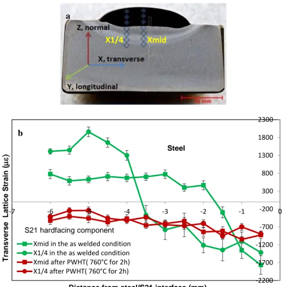
First, we explored the effects of the PWHT on microstructure, hardness and residual stresses of the hardfacing components to reduce the risk of failures introduced in process. The PWHT was found to soften the high-hardness HAZ in the steel significantly due to the formation of the tempered-martensitic microstructure. Moreover, it can reduce the residual stresses in steel substantially and homogenize the strains across the hardfacing component.
After manufacturing, we studied the F91/S21 interfacial microstructure evolution of the problematic S21 hardfacing components. A layer was found to grow along the F91/S21 interface during aging, which follows a parabolic rate of growth. Three phases including an (Fe,Co)(Cr,Mo)-type σ phase and a Cr-rich M23C6-type carbide were identified in this interfacial
S21 and the F91 materials due to the presence of the hard σ phase and M23C6 carbides. The M23C6
carbides were found to grow with aging temperature and time. However, lesser amount of the σ phase was observed at higher temperatures studied.
Following the exploration of the F91/S21 interfacial microstructure evolution, we investigated the effects of F91/S21 interfacial microstructure on the mechanical properties of S21 hardfacing components by means of Charpy impact testing. An innovative Charpy U-notch geometry was designed. That is, the F91/S21 interface was centered in the notch. The significant decrease in impact energy after aging is resulted from the interfacial layer formed, where the primary cracks propagate. The aged S21 hardfacing components were found to fail in a brittle fashion. Both the the σ phase and M23C6 carbides were found to contribute to the toughness degradation during the
impact testing, though the M23C6 carbides play a more important role than the σ phase. It is
proposed that these two hard phases are the microstructural causes for the delamination of Stellite hardfacing from valves.
Then, we performed a comparative study on the microstructure evolution and mechanical properties of hardfacing components using the IN82 alloy as an alternative to the problematic S21 buffer layer. Compared with the S21 hardfacing components, no deleterious interfacial layer was observed along the F91/IN82 interface after aging. The impact toughness degradation in the IN82 hardfacing components was found to be much less significant than that of the S21, and in addition, to be related to coarsening and precipitation of the intergranular/interdendritic carbides in the IN82 bulk material rather than the F91/IN82 interface.
In addition to the IN82 alloy, the IN625 hardfacing components were investigated due to low cost. Both the F91/IN625 interface and the IN625 bulk material were found to be not as stable as the IN82 hardfacing components because of the presence of precipitates during aging. Though the F91/IN625 interface is not the weakest link during the tensile testing, some Charpy specimens were found to fail along the F91/IN625 interface possibly resulted from the precipitates parallel to the interface. The impact energy loss is significant (88%) after aging at 650 °C for 8760 h. It is not recommended to use the IN625 buffer layer.
Finally, the examination of an ex-service wedge gate valve validates our laboratory study on the S21 hardfacing components. The delamination crack was observed in the zones enriched with the σ phase of the S21 bulk material. It is because large amounts of the σ phase precipitate deeply into
the S21 bulk material via the grain boundary diffusion path after years of service. The service time and temperature of this ex-service component fulfill the expected equivalent time and temperature by extrapolation.
During service of valves, in addition to aging, there are other factors such as thermal cycling and operation induced stresses (opening and closing of valves). They were not taken into account by our experimentation. However, we do believe that the objectives of this work have been fulfilled. Namely, the causes of the premature failures have been identified and the alternative solutions to enhance the durability of the hardfacing components have been validated.
To meet the challenge of delamination of hardfacing alloys from high-temperature valves, the IN82 buffer layer is a good alternative to replace the problematic S21 buffer layer, which can enhance the durability of the hardfacing components. However, due to higher dilution of Fe and Ni, the hardness of S6 top layer deposited on the IN82 buffer layer is compromised compared with the S6 deposited over the S21 buffer layer. To mitigate this downside, it is proposed that more S6 layers can be deposited to maintain its hardness according to the applications. Moreover, the welding parameters used during manufacturing can be optimized to reduce the dilution, and thus to maintain the S6 hardness.
TABLE OF CONTENTS
ACKNOWLEDGEMENTS ... III RÉSUMÉ ... V ABSTRACT ... IX TABLE OF CONTENTS ...XII LIST OF TABLES ... XVII LIST OF FIGURES ... XIX LIST OF SYMBOLS AND ABBREVIATIONS... XXVII LIST OF APPENDICES ... XXX
CHAPTER 1 INTRODUCTION ... 1
1.1 Context ... 1
1.2 Objectives ... 4
CHAPTER 2 GENERAL ORGANIZATION OF THE THESIS ... 6
CHAPTER 3 LITERATURE REVIEW ... 9
3.1 Hardfacing ... 9
3.1.1 Introduction ... 9
3.1.2 Hardfacing process ... 9
3.1.2.1 Gas tungsten arc welding ... 10
3.1.2.2 Plasma-transferred arc welding ... 11
3.1.2.3 Laser hardfacing ... 12
3.1.3 Hardfacing materials [18] ... 13
3.1.3.1 Cobalt-based hardfacing alloys ... 13
3.1.3.2 Nickel-based hardfacing alloys ... 15
3.1.4 Preheat treatment and post-weld heat treatment ... 16
3.2 Creep-resistant steels ... 17
3.2.1 Development of 9–12% Cr martensitic steels ... 17
3.2.2 Background on grade 91 and 92 steels ... 18
3.2.3 Microstructure of 9–12% Cr martensitic steels ... 20
3.3 Failures of Stellite hardfacing in the power generation industry ... 22
CHAPTER 4 EXPERIMENTAL METHODOLOGY ... 25
4.1 Materials and hardfacing deposition ... 25
4.2 Sample preparation for strain/stress measurements ... 25
4.3 Manufacturing of the hardfacing assembly ... 26
4.4 Aging ... 27
4.5 Machining ... 28
4.6 Metallographic techniques ... 29
4.7 Mechanical characterization ... 29
4.7.1 Indentation testing ... 29
4.7.2 Charpy impact testing ... 31
4.7.3 Tensile testing coupled with digital image correlation ... 32
4.8 Microstructural characterization ... 33
4.8.1 Optical microscopy ... 33
4.8.2 Scanning electron microscopy ... 34
4.8.3 Electron backscatter diffraction ... 35
4.8.4 X-ray diffraction ... 36
4.9 Residual strain/stress measurements ... 36
CHAPTER 5 EFFECTS OF THE PWHT ON MICROSTRUCTURE AND PROPERTIES OF THE HARDFACING COMPONENTS ... 41
5.1 Effect of the PWHT on hardness ... 41
5.2 Effect of the PWHT on steel microstructure ... 42
5.3 Effect of the PWHT on residual strains/stresses ... 44
CHAPTER 6 ARTICLE 1: THERMAL STABILITY OF A STELLITE/STEEL HARDFACING INTERFACE DURING LONG-TERM AGING ... 47
6.1 Introduction ... 48
6.2 Experimental details ... 50
6.2.1 Materials, deposition and aging ... 50
6.2.2 Microstructural analysis ... 52
6.2.3 Indentation ... 54
6.3 Results ... 55
6.3.1 F91/S21 interfacial microstructure ... 55
6.3.2 Indentation on the F91/S21interface ... 62
6.4 Discussion ... 65
6.5 Conclusions ... 74
6.6 Acknowledgments ... 74
CHAPTER 7 ARTICLE 2: EFFECT OF INTERFACIAL MICROSTRUCTURE ON MECHANICAL PROPERTIES OF COBALT-BASED HARDFACING DURING LONG-TERM AGING………… ... 75 7.1 Introduction ... 75 7.2 Experimental details ... 78 7.2.1 Sample preparation ... 78 7.2.2 Microstructural analysis ... 80 7.2.3 Mechanical testing ... 81 7.3 Results ... 81
7.3.1 F91/S21 interfacial microstructure ... 81
7.3.2 Nanoindentation on the F91/S21 interface ... 82
7.3.3 Charpy impact testing ... 83
7.3.4 SEM observation on cross-sections of fractured specimens ... 86
7.3.5 SEM Fractographic observation ... 88
7.4 Discussion ... 89
7.5 Conclusions ... 92
7.6 Acknowledgments ... 93
CHAPTER 8 ARTICLE 3: MICROSTRUCTURAL AND MECHANICAL CHARACTERIZATION OF STELLITE HARDFACING WITH TWO TYPES OF BUFFER LAYERS…………. ... 94 8.1 Introduction ... 95 8.2 Experimental details ... 96 8.2.1 Sample preparation ... 96 8.2.2 Mechanical characterization ... 99 8.2.3 Microstructural analysis ... 100 8.3 Results ... 101
8.3.1 Charpy impact energy evolution ... 101
8.3.2 Fracture analysis of the IN82 and S21 specimens ... 102
8.3.3 F91/IN82 and F91/S21 interfacial microstructure ... 104
8.3.4 Microhardness and nanohardness testing ... 109
8.4 Discussion ... 112
8.5 Conclusions ... 115
8.6 Acknowledgments ... 115
9.1 Microstructural evolution ... 116
9.2 Mechanical testing ... 120
9.2.1 Indention testing ... 120
9.2.2 Charpy impact testing ... 123
9.2.3 Tensile testing coupled with DIC ... 124
9.2.3.1 Straight-shank specimen ... 124
9.2.3.2 Notched specimen ... 126
CHAPTER 10 AN EX-SERVICE WEDGE GATE VALVE STUDY ... 130
CHAPTER 11 GENERAL DISCUSSION ... 136
CHAPTER 12 CONCLUSIONS AND PERSPECTIVES ... 142
12.1 Conclusions ... 142
12.2 Perspectives ... 144
REFERENCES ... 146
LIST OF TABLES
Table 2.1 Peer reviewed publications related to this work. ... 8
Table 2.2: Contributions to conferences. ... 8
Table 3.1: Nominal chemical compositions of three Co-based alloys (wt%) [19]. ... 14
Table 3.2: Nominal chemical compositions of two Ni-based alloys (wt%) [21]. ... 15
Table 3.3: Evolution of martensitic steels used in the power generation industry [25]. ... 18
Table 3.4: chemical compositions of P91 and P92 steels [30]. ... 19
Table 3.5: Summary of field experience in hardfacing disbonding from EPRI database [3]. ... 23
Table 4.1: Three types of hardfacing configurations. ... 25
Table 4.2: Sample conditions used for neutron diffraction measurements. ... 26
Table 4.3: Aging conditions of the three types of hardfacing components. ... 27
Table 6.1: Chemical compositions of F91, S21 and S6 (wt%). ... 51
Table 6.2: Welding conditions used for S21 and S6 deposition. ... 51
Table 6.3: Aging conditions. ... 52
Table 6.4: Chemical compositions of phases A, B, C, F91, and S21 (wt%). ... 60
Table 6.5: Microhardness values of the interfacial layer, the F91 and the S21 (200 mN). ... 63
Table 6.6: mechanical properties of the three phases observed in the interfacial layer. ... 65
Table 6.7: Activation energies of some elements for diffusion in Co. ... 67
Table 6.8: Activation energies of some phases. ... 67
Table 7.1: Chemical compositions of F91, S21 and S6 (wt%). ... 78
Table 7.2: Welding conditions used for S21 and S6 deposition. ... 78
Table 7.3: Aging conditions. ... 80
Table 8.1: Chemical compositions of F91, IN82, S21, and S6 (wt%). ... 97
Table 8.3: Aging conditions. ... 98 Table 10.1: Representative EDS spot measurements on the three phases (wt%). ... 134
LIST OF FIGURES
Figure 1.1: A pie chart illustrating numerical proportions of U.S. greenhouse gas emissions by
economic sector in 2017 [1]. ... 1
Figure 1.2: A Velan parallel slide gate valve (courtesy of Velan Inc.). ... 2
Figure 1.3: Coefficient of thermal expansion of several alloys [3]. ... 3
Figure 1.4: A schematic showing the delamination between the S21 and the grade 91 [4]. ... 4
Figure 3.1: Schematic representation of a gas tungsten arc welding process [7]. ... 10
Figure 3.2: Schematic illustration of PTA welding process [9]. ... 11
Figure 3.3: Schematic illustration of a laser hardfacing process [16]. ... 12
Figure 3.4: SEM micrographs of (a) S6 and (b) S21 showing the dendrite structure. ... 15
Figure 3.5: SEM micrographs of (a) IN82 [22] and (b) IN625 showing the dendrite structure. ... 16
Figure 3.6: As-tempered microstructure of 9–12% Cr steels: (a) and (b) schematic illustration [32], and (c) optical micrograph. ... 20
Figure 3.7: Schematic illustration of microstructure of 9–12% Cr steel (a) as tempered and (b) after creep exposure [37]. ... 21
Figure 3.8: (a) Delamination of an upstream seat ring and (b) hardfacing debris from a combined stop and control valve [6]. ... 22
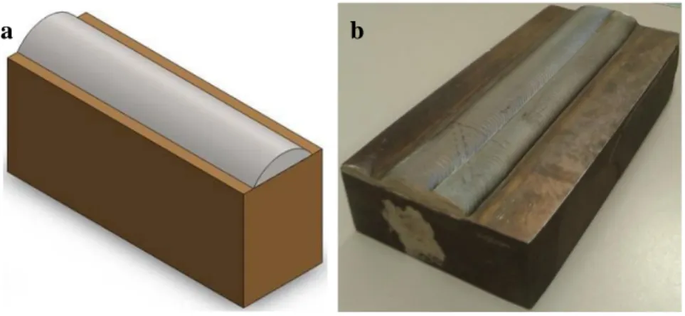
Figure 4.1: Hardfacing component: (a) illustration and (b) manufactured. ... 26
Figure 4.2: A montage of 5× optical images showing the cross-section of a hardfaing component: F91 base material, buffer layer S21, 1st and 2nd layers of S6, and filler material IN625. ... 27
Figure 4.3: The three-dimensional illustration of a Charpy U-notch specimen. ... 28
Figure 4.4: (a) A machined straight-shank tensile specimen, (b) its three-dimensional illustration, and (c) three-dimensional illustration of the notched tensile specimen. ... 28
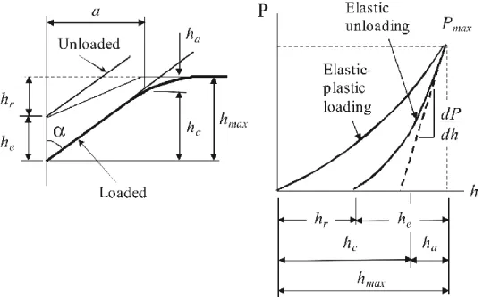
Figure 4.5: Depth-sensing indentation: (a) schematic representation of the cross-section of an indentation at full load and unload and (b) typical load-displacement curve for elastic–plastic loading followed by elastic unloading [47]. ... 30
Figure 4.6: There types of Charpy (simple-beam) specimens [44]. ... 31
Figure 4.7: The speckle pattern on the surface of a tensile specimen. ... 32
Figure 4.8: Tensile testing setup combined with the DIC. ... 33
Figure 4.9: Schematic of the diffracting cones with respect to the diffracting plane, the sample, and the phosphor screen in three dimensional space [49]. ... 35
Figure 4.10: L3 Diffractometer in Chalk River. ... 37
Figure 4.11: Schematic layout of the L3 Diffractometer for strain measurement [50]. ... 37
Figure 4.12: Matchstick-like reference samples. ... 38
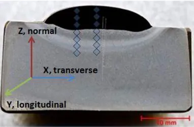
Figure 4.13: Mounted samples showing strain measurements along (a) normal, (b) transverse and (c) longitudinal directions; (d) a hardfacing component showing the three directions. ... 39
Figure 4.14: Cross-section of a hardfacing component with neutron diffraction measurement locations indicated. ... 39
Figure 5.1: Hardness profiles of the S21 samples in the as-welded condition and after the PWHT. ... 41
Figure 5.2: Microstructure change of the HAZ in the steel from the interface to the unaffected steel: (a), (b), (c), and (d) in the as-welded condition; (e), (f), (g), and (h) after the PWHT. ... 42
Figure 5.3: Residual stresses along three directions of the S21 samples in the as-welded condition and after the PWHT. ... 44
Figure 5.4: (a) A graph showing the measurements performed at the middle and a quarter of the weld bead and (b) transverse lattice strains across the weld in the as-welded condition and after the PWHT. ... 45
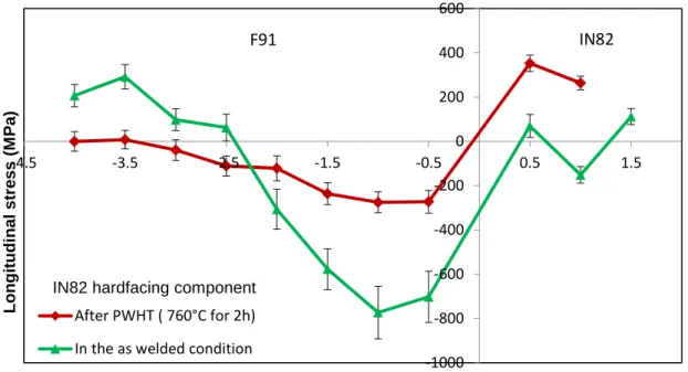
Figure 5.5: Longitudinal stress distribution of the IN82 samples in the as-welded condition and after the PWHT. ... 46
Figure 6.1: Schematic illustration of the methodology used to obtain the length fractions of the σ-phase-rich zones and the reactive zones along grain boundaries, at the interface between the S21 hardfacing and the F91 substrate. ... 53
Figure 6.2: Optical micrographs of the F91/S21 interfacial microstructure under different conditions: (a) as-tempered condition; (b) 550 °C, (c) 600 °C and (d) 650 °C for 8760 h; (e) 600 °C for 8760 h showing the growth along grain boundaries, and (f) 550 °C for 8760 h showing a thicker zone. ... 55 Figure 6.3: (a) Growth kinetics of the interfacial layer with a double logarithmic scale and (b)
Arrhenius plot of ln(𝑘) versus 103/𝑇. ... 56
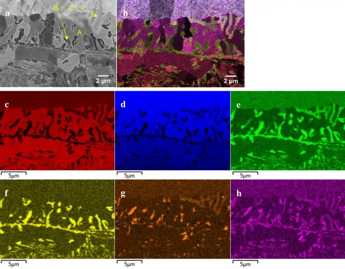
Figure 6.4: BSE images showing the interfacial microstructure: (a) 550 °C, (b) 600 °C and (c) 650 °C for 1008 h; (d) 550 °C, (e) 600°C and (f) 650°C for 3600 h; (g) 550 °C, (h) 600 °C and (i) 650 °C for 8760 h; (j) 550 °C for 8760 h showing the growth along grain boundaries observed in Figure 6.2e; (k) 550 °C for 8760 h showing the lamellar structure observed in Figure 6.2f; and (l) in the as-tempered condition. ... 58 Figure 6.5: EDS elemental mapping on the interface of the sample aged at 600 °C for 8760 h: (a)
BSE image; (b) EDS composite map; (c) Fe, (d) Co, (e) Cr, (f) C, (g) Si and (h) Mo elemental maps. ... 59 Figure 6.6: The interface of a sample aged at 550 °C for 8760 h (a) band contrast map, (b) the
corresponding EBSD phase map (γ-Co in yellow, ε-Co in pink, α-Fe and FexCoy in blue,
M23C6 in green, in red, and black no signal), and (c) the corresponding EDS composite map
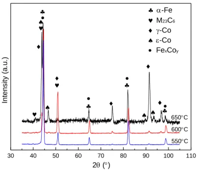
(Fe, Co, Cr, C, Si, and Mo); the interface of a sample aged at 650 °C for 8760 h (d) band contrast map, (e) the corresponding EBSD phase map, and (f) the corresponding EDS composite map (Fe, Co, Cr, C, Si, and Mo). ... 61 Figure 6.7: XRD patterns of the F91/S21interfaces at 550, 600 and 650 °C for 8760 h. ... 62 Figure 6.8: A sample aged at 600 °C for 8760 h (a) hardness map, (b) the corresponding BSE image
and (c) the corresponding EDS composite map (the phase in light green 2, the M23C6
carbides in green 1 and the FexCoy in purple). ... 64
Figure 6.9: EDS line scan measurements showing composition profiles across the interface between F91 and S21 of the hardfacing sample in the as-tempered condition. ... 66 Figure 6.10: Schematic illustration of three diffusion regimes in Harrison’s classification. ... 68 Figure 6.11: Area fraction of the σ phase aged at 550, 600 and 650 °C for 8760 h. ... 69
Figure 6.12: Schematic illustration of the σ-phase-rich zones aged at (a) 550, (b) 600 and (c) 650 °C for 8760 h (colored zone: interfacial layer). ... 70 Figure 6.13: Area fraction of the M23C6 carbides. ... 72
Figure 6.14: Equivalent diameter of the M23C6 carbides (The straight lines in the right-side plot,
connecting each individual data point, have no physical significance.). ... 73 Figure 7.1: Charpy specimen manufacturing: (a) F91 extension, (b) Stellite-hardfaced coating with
buffer layer of S21 and top layer of S6, (c) assembly made by welding an F91 extension to the Stellite-hardfaced coating sample using IN625 as the filler material, (d) bars cut from the assembly, and (e) Charpy U-notch specimen machined from the half bars (cross-section). . 79 Figure 7.2: BSE images showing the F91/S21 interfacial microstructure: (a) in the as-tempered
condition and (b) after aging at 650 °C for 8760 h. ... 82 Figure 7.3: A sample aged at 650 °C for 8760 h (a) hardness map, (b) the corresponding BSE image
and (c) the corresponding EDS composite map. ... 83 Figure 7.4: (a) Charpy impact energy evolution of F91 and hardfacing specimens and (b)
magnification of (a) for the hardfacing specimens after aging. The straight lines, connecting each individual data point, have no physical significance. ... 84 Figure 7.5: Representative back-faces of the fractured Charpy specimens (a) in the as-tempered
condition and (b) after aging; representative macro-fracture surfaces of Charpy specimens (c) in the as-tempered condition and (d) after aging. ... 85 Figure 7.6: Cross-sections showing the fracture along the interfacial layer (a) and (b) at 550 °C
8760 h, (c) and (d) at 600 °C 8760 h, and (e) and (f) at 650 °C for 8760 h (the crack propagation direction was perpendicular to the cross-section). ... 86 Figure 7.7: BSE images and EDS layered maps showing the secondary cracks at 600 °C for 8760 h
(a), (b), (c) (d), (e), and (f); and at 650 °C for 8760 h (g) and (h). ... 87 Figure 7.8: Representative fractographs of a hardfacing specimen in the as-tempered condition: (a)
macro-fractograph, (b) higher magnification view of zone 1, and (c) higher magnification view of zone 2. ... 88
Figure 7.9: A hardfacing specimen aged at 600 °C for 8760 h: (a) macro-fractograph, (b) SEM fractograph from zone 1, (c) EDS map of the zone outlined by the rectangle in (b) and EDS spot measurement on the reddish zone, (d) SEM fractograph from zone 2, and (e) EDS map of (d). ... 89 Figure 7.10: Relationship between the impact energy loss percentage and the interfacial layer
thickness or the equivalent diameter of the M23C6 carbides for the specimens aged at 550, 600
and 650 °C for 1008, 3600 and 8760 h, with exponential and linear best-fit regressions. .... 90 Figure 7.11: Relationship between the impact energy loss percentage and area fractions of the
M23C6 carbides and the phase for the specimens aged at 550, 600 and 650 °C for 8760 h.
The straight lines, connecting each individual data point, have no physical significance. .... 91 Figure 8.1: Charpy specimen manufacturing: (a) F91 extension, (b) hardfaced-coating sample with
buffer layer of IN82 or S21 and top layer of S6, (c) assembly made by welding an F91 extension to the hardfaced-coating sample using IN625 as the filler material, (d) two halves cut from each bar, and (e) Charpy U-notch specimen machined from the half bars [22]. ... 98 Figure 8.2: Charpy impact energy evolution of the IN82 and S21 hardfacing specimens. ... 101 Figure 8.3: Fractured Charpy specimens after aging at 650 °C for 8760 h: representative
cross-sections (a) S21 and (b) IN82; representative back-faces (c) S21 and (d) IN82; representative macro-fracture surfaces (e) S21 and (f) IN82. ... 102 Figure 8.4: SEM fractographs of an S21 specimen aged at 650 °C for 8760 h: (a), (b) and (c)
showing cleavage and quasi-cleavage; (d) EDS map obtained from the fracture surface (M23C6
in green and FexCoy in purple). ... 103
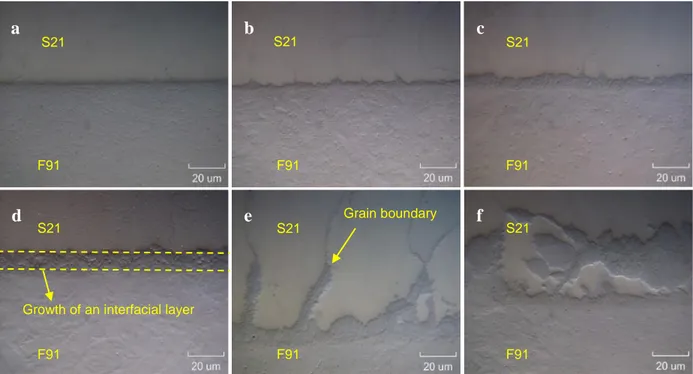
Figure 8.5: SEM micrographs of an IN82 specimen aged at 650 °C for 8760 h: (a) dendritic microstructure; (b) the intergranular/interdendritic cracks, (c) higher magnification view, and (d) the zone outlined by the rectangle showing the microvoids surrounded by dimples. .... 104 Figure 8.6: SEM images showing the interfacial microstructure: S21 (a) as-tempered and (b) aged
at 650 °C 8760 h, IN82 (c) as-tempered and (d) aged at 650 °C 8760 h (the inset image in secondary-electron mode, others in backscattered-electron (BSE) mode). ... 105
Figure 8.7: EDS elemental mapping on the F91/IN82 interface of a specimen aged at 650 °C for 8760 h: (a) EDS composite map; (b) Mo, (c) Cr, (d) C, (e) Fe, and (f) Ni elemental maps. ... 106 Figure 8.8: The F91/IN82 interface of a specimen aged at 650 °C for 8760 h (a) band contrast map,
(b) the corresponding EBSD phase map (γ-Ni in purple, α-Fe in blue, M23C6 in green, and
NbC in light blue), and (c) the corresponding EDS composite map. ... 107 Figure 8.9: Elemental concentration profiles of the as-tempered IN82 hardfacing specimen. .... 108 Figure 8.10: Fe concentrations measured in F91, buffer layer S21 or IN82, the first layer of S6
(S6-1), and the second layer of S6 (S6-2) in the as-tempered (AT) condition and after aging at 650 °C for 8760 h. ... 108 Figure 8.11: Microhardness profiles of the S21 and IN82 specimens aged at 650 °C for 0, 1008,
3600, and 8760 h. ... 109 Figure 8.12: An S21 specimen aged at 650 °C for 8760 h (a) hardness map, (b) the corresponding
BSE image and (c) the corresponding EDS composite map (M23C6 carbides in green); an IN82
specimen aged at 650 °C for 8760 h (d) hardness map, (e) the corresponding BSE image and (f) the corresponding EDS composite map (M23C6 carbides in green). ... 111
Figure 9.1: SEM images showing the interfacial microstructure (a) IN625 and (b) IN82 [22] aged at 650 °C for 8760 h. ... 116 Figure 9.2: SEM images showing IN625 (a) dendrite microstructure and (b) the zone outlined by
the rectangle after aging at 650 °C for 8760 h. ... 117 Figure 9.3: EDS elemental mapping on the IN625 bulk material after aging at 650 °C for 8760 h:
(a) EDS composite map; (b) C, (c) Nb, (d) Si, (e) Mo, (f) Fe, (g) Ni, and (h) Cr elemental maps. ... 118 Figure 9.4: EDS spot measurements on type A and B precipitates: (a) BSE image; (b) a spectrum
obtained from type B precipitate, and (c) a spectrum obtained from type A precipitate. .... 119 Figure 9.5: XRD patterns of the F91/IN625 and F91/IN82 interfaces after aging at 650 °C for
Figure 9.6: Microhardness profiles of the IN625 samples: (a) as-tempered condition; aged at 550, 600, 650, and 700 °C for 1008 h. ... 121 Figure 9.7: Microhardness profiles of the IN625 samples: as-tempered condition; aged at 650 °C
for 1008 and 3600 h. ... 122 Figure 9.8: Impact energy evolution of the S21, IN625 and IN82 hardfacing specimens. ... 123 Figure 9.9: IN625 Charpy specimens after aging at 650 °C for 8760 h: showing fracture along the
F91/IN625 interface (a) before fracture, (b) cross-section and (c) back-face after fracture; showing fracture in the IN625 (d) before fracture, (e) cross-section and (f) back-face after fracture. ... 124 Figure 9.10: Principle strain maps of a tensile specimen aged at 550 °C for 1008 h: (a) before and
(b) after fracture. ... 125 Figure 9.11: Local stress-strain curves obtained from F91, IN625 and S6. ... 126 Figure 9.12: A notched specimen in the as-tempered condition: principle strain maps (a) before and
(b) after fracture, (c) illustration showing the fracture, and (d) the other side of the fractured specimen. ... 127 Figure 9.13: A fractured IN625 specimen in the as-tempered condition: (a) cross-section, (b)
fractograph and (c) EDS spot measurement on the fracture surface. ... 128 Figure 9.14: A notched specimen aged at 650 °C for 1008 h: principle strain maps (a) before and
(b) after fracture, the other side of the specimen (c) before and (d) after fracture. ... 129 Figure 10.1: An ex-service wedge gate valve. ... 130 Figure 10.2: Sampling location and a sample after cutting. ... 130 Figure 10.3: The cross-section of this sample after metallographic preparation. ... 131 Figure 10.4: (a) OM micrographs showing the full cross-section; (b), (c), (d) and (e) higher SEM
magnification views. ... 131 Figure 10.5: Steel/S21 interfacial microstructure: (a) and (b) from the ex-service component; from
the laboratory sample aged at 550 °C for 8760 h (c) and (d) polished up to 1 µm, (e) and (f) further polished using a mixed colloidal silica suspension. ... 132
Figure 10.6: EDS spot measurements on the ex-service component. ... 133 Figure 10.7: (a) Primary crack and (b) secondary cracks observed in the σ-phase-rich zones. ... 134
LIST OF SYMBOLS AND ABBREVIATIONS
Symbols
𝜀 Residual strain 𝜃 Incidence angle 𝜆 Wavelength ν Poisson's Ratio 𝜎 Residual stress 𝐴 Projected area 𝐶 Material constant 𝐸 Young’s modulus𝐸max Maximum impact energy
𝐸min Minimum impact energy
∆𝐸avg Uncertainty in the mean value of impact energy 𝐻 Hardness
𝐻max Maximum hardness
𝐻min Minimum hardness
𝐻𝑃 Hollomon-Jaffe parameter
∆𝐻avg Uncertainty in the mean value of hardness 𝑘 Growth rate constant
𝑘0 Pre-exponential coefficient
𝑁 Number of measurements 𝑃 Applied load
𝑄 Activation energy 𝑅 Gas constant
𝑇 Temperature
𝑡 Time
𝑥 Thickness of the interfacial layer
Abbreviations
ASTM American Society for Testing and Materials AT As tempered
BCC Body-centered cubic BSE Backscattered electron DIC Digital image correlation
EBSD Electron backscattered diffraction EDS Energy dispersive spectroscopy EPRI Electric Power Research Institute HAZ Heat-affected zone
HRH Hot reheat section of a boiler HRSG Heat recovery steam generator HV Vickers hardness
IN625 Inconel 625 IN82 Inconel 82
NSERC Natural Science and Engineering Research Council OM Optical microscopy
PMZ Partially mixed zone PSGV Parallel sliding gate valve PSGVC Parallel sliding gate valve PTA Plasma transferred arc
PWHT Post-weld heat treatment S21 Stellite 21
S6 Stellite 6
SE Secondary electron
SEM Scanning electron microscopy XRD X-ray diffraction
LIST OF APPENDICES
Appendix A – drawing of a pocket machined from the sample ... 154 Appendix B – drawings of reference samples ... 155 Appendix C – drawings of the assemblies ... 157 Appendix D – drawing of the Charpy U-notch specimen ... 159 Appendix E – drawings of the tensile specimens ... 160 Appendix F – residual stress/strain distributions ... 162 Appendix G – tensile tesing of the IN82 and S21 specimens ... 164
CHAPTER 1
INTRODUCTION
1.1 Context
In power plants, electric power is generated through the conversion of other energy sources. For example, fossil fuels such as coal and oil are burnt to produce electricity in most power plants in the world. However, the produced carbon dioxide emissions into the atmosphere absorb solar energy and trap heat close to the surface of Earth, which is known as the greenhouse effect. Greenhouse gases including carbon dioxide drive global warming and global climate change. Reducing greenhouse gas emissions has been agreed by many countries. According to United States Environmental Protection Agency, the second largest share of greenhouse gas emissions comes from burning fossil fuels for electricity, as shown in Figure 1.1 [1]. Material scientists have made every endeavor to advance material technology to improve the thermal power generation efficiency. That is, steam temperature and pressure are increased to reduce use of fossil fuels, and thus to reduce carbon dioxide and other environmentally hazardous gas emissions.
Figure 1.1: A pie chart illustrating numerical proportions of U.S. greenhouse gas emissions by economic sector in 2017 [1].
The steam created in the power generation industry operates a steam turbine and generator that then generates electricity. Accordingly, the steam needs to be controlled. Thus, steam control valves, essential components of a piping system, play an important part in controlling the flow and pressure of steam within a system or process. Valves are used to start and stop the steam flow, to regulate the flow or the process pressure, and to control the direction of the flow. Valve designs, models and types are many. A parallel slide gate valve manufactured by Velan is illustrated in Figure 1.2. Valve seats and disks are shown on the right side of Figure 1.2, which are removable and replaceable internal parts that are in contact with the steam flow. The disk is able to start, stop, or throttle the steam flow depending on its position (fully or partially opening or closing). Disks are usually forged and hardfacing alloys are often deposited on their surfaces to provide wear, oxidation and corrosion resistance. The seat provides the seating surface for the disk and they together form a seal to stop the steam flow. As shown in Figure 1.2, there are two seats in this parallel slide gate valve. Hardfacing alloys are also often deposited on the seating surfaces, which are then machined to reach a fine surface finish for tight sealing.
Figure 1.2: A Velan parallel slide gate valve (courtesy of Velan Inc.).
Hardfacing alloys are normally classified as iron-, nickel- and cobalt-based alloys. With regard to the hardfacing alloys used in the conventional power generation industry, a cobalt-based alloy
Hardfaced seat
Stellite 6 (S6) has gained popularity for decades. Stolof concluded that the S6 alloy exhibited high hot hardness through the formation of complex carbides and good oxidation resistance provided by its high chromium content (about 30%) [2]. For some applications, the S6 alloy is applied directly on the steel substrate; for other applications, Stellite 21 (S21) alloy is used as a buffer layer (also referred to as a butter layer) between the steel substrate and the S6 top layer. One reason to use the S21 (alloy 21) is to bridge the thermal expansion gap between the steel substrate (grade 91) and the S6 (alloy 6) due to its intermediate thermal expansion, as shown in Figure 1.3 [3]. The S21 is also a cobalt-based alloy but less resistant to wear than S6.
Figure 1.3: Coefficient of thermal expansion of several alloys [3].
Valves used in the conventional power generation industry are usually made of creep-resistant steels due to the elevated-temperature application. For example, valve components are manufactured using grade 91 steel, a tempered-martensitic steel. When the valve components need to be wear resistant, hardfacing alloys such as the S21 and the S6 alloys are applied on the component surfaces by hardfacing processes. Among the processes, plasma-transferred arc (PTA) welding is often used due to its advantages such as automation. When the Stellite alloys are
deposited on the steel substrate during welding, alloy mixing occurs due to melting of part of the steel substrate. Therefore, phase transformation may take place during manufacturing or service. A major industry challenge in the form of delamination of cobalt-based hardfacing alloys from valve seats or disks during service has presented itself to the power generation industry. One such failure is illustrated in Figure 1.4 [4], where a delamination crack is growing between the S21 buffer layer and the grade 91 steel. These failures were documented by the Electric Power Research Institute (EPRI) in a technical update report in 2015 [3]. In 2011 and 2012, a leading valve services company repaired more than 25 valves due to the Stellite delamination failures [5]. These failures may cause steam leakage. Consequently, thermal efficiency of power plants is reduced, more fossil fuels are burnt to produce electricity, and thus more carbon dioxide is emitted into the atmosphere. In addition, the free hardfacing debris could damage other components within the system [6]. In response to this challenge, this PhD project was defined within the program of the Multisectorial Industrial Research Chair in Coatings and Surface Engineering, partnered by Montreal-based valve manufacturing company Velan Inc.
Figure 1.4: A schematic showing the delamination between the S21 and the grade 91 [4].
1.2 Objectives
In the context of this PhD project and of the needs of our industrial partner, we focus on comprehending the causes of the premature failures and investigating the alternative solutions to enhance the durability of the hardfacing components. This requires a thorough characterization of
the microstructure and mechanical properties of the hardfacing components during manufacturing and service, and an exploration of alternative materials to develop optimized Stellite hardfacing components using the existing state-of-the-art. In order to accomplish the main goals of this project, the specific objectives are set as follows:
To explore the effects of the post-weld heat treatment (PWHT) on the microstructure and properties of the hardfacing components;
To investigate the effects of long-term aging on the microstructure evolution of the hardfacing components;
To study the effects of the microstructure evolution on the mechanical properties of the hardfacing components;
To evaluate the effects of the alternative buffer layers on the durability of the hardfacing components.
CHAPTER 2
GENERAL ORGANIZATION OF THE THESIS
This thesis comprises twelve chapters including the introduction and general organization of the thesis. Chapter 3 presents the background information about hardfacing processes, hardfacing materials, and 9–12% Cr martensitic/ferritic steels. At the end of chapter 3, the premature failures of Stellite hardfacing in the steam power generation industry and the relevant studies are detailed. The experimental methods including the hardfacing deposition, and microstructural and mechanical characterization are described in chapter 4. The thesis body includes chapters 5 to 10 where the mains results were compiled in three journal papers (chapters 6, 7 and 8) and 3 complementary topics. A general discussion linking the results together and explaining the limitations of the work precedes the conclusions and perspectives.
To reduce the failures induced during the manufacturing process, the effects of the PWHT on microstructure, hardness and residual stresses of the hardfacing components were studied in chapter 5. It will be shown that the PWHT effectively tempers the microstructure of heat-affected zone (HAZ) in the steel, and thus significantly softens the high-hardness HAZ. In addition, the PWHT not only reduces the residual stresses in steel significantly, but also homogenizes the strains across the hardfacing component.
After the PWHT study, the effects of long-term aging on the F91/S21 interfacial microstructure were explored in chapter 6 (Article 1). It will be shown that three phases including an (Fe,Co)(Cr,Mo)-type σ phase and a Cr-rich M23C6-type carbide are formed in the F91/S21
interfacial layer after aging. It will also be shown that the σ phase and the M23C6 carbides are the
hardest among the studied phases. The deleterious phases in the interfacial layer may cause the delamination of valves in service due to their high hardness.
To validate the above hypothesis, the F91/S21 interfacial microstructure is correlated with its toughness using Charpy impact testing in chapter 7 (Article 2). It will be shown that this interfacial layer formed during aging provides a brittle crack propagation pathway under the high-strain rate impact. The impact energy loss is mainly associated with the brittle M23C6 carbides and σ phase in
the interfacial layer. Therefore, it will be concluded that the microstructural causes of the delamination of valve components are the σ phase and the M23C6 carbides formed along the
Since the damage mechanism is clear, an Inconel 82 (IN82) buffer layer was evaluated to replace the problematic S21 buffer layer in chapter 8 (Article 3). A comparative study on the microstructure and mechanical properties of IN82 and S21 hardfacing components was performed. It will be shown that the F91/IN82 interface is much more stable than the F91/S21 interface after aging at 650 °C for 8760 h. The impact energy loss of the IN82 components is much less significant than that of the S21 after aging. Thus, the IN82 buffer layer is recommended to replace the problematic S21 to enhance the durability of the hardfacing components.
Following the evaluation of the IN82 buffer layer, another nickel-base alloy Inconel 625 (IN625) was also investigated due to its low cost in chapter 9. However, it will be shown that the IN625 is not recommended to be used as a buffer layer due to its unstable microstructure and mechanical properties.
To transfer our obtained laboratory knowledge to the industry, the case study of an ex-service wedge gate valve was undertaken in chapter 10. It will be shown that the results and discussion obtained from the laboratory experiments in chapter 6 and 7 provide a solid explanation for the delamination crack observed in the zones enriched with the σ phase of this ex-service wedge gate valve.
Finally, in the last two chapters, the general discussion linking the results together is presented and the limitations of this work are addressed as well. The main results of this work accomplished are summarized, followed by the relevant ideas, interests and recommendations with respect to the hardfacing components.
This research work resulted in the three publications, as listed in Table 2.1. In addition, some results of this work were presented at conferences, as summarized in Table 2.2.
Table 2.1 Peer reviewed publications related to this work.
Y. Wu, E. Bousser, T. Schmitt, N. Tarfa, F. Khelfaoui, R. René, J. Klemberg-Sapieha, and M. Brochu, "Thermal stability of a Stellite/steel hardfacing interface during long-term aging,"
Materials Characterization, vol. 154, pp. 181-192, 2019.
Y. Wu, T. Schmitt, E. Bousser, F. Khelfaoui, V. Najarian, J. Klemberg-Sapieha, and M. Brochu, "Effect of interfacial microstructure on mechanical properties of cobalt-based hardfacing during long-term aging," Submitted.
Y. Wu, T. Schmitt, E. Bousser, N. Tarfa, L. Vernhes, F. Khelfaoui, G. Perez, J. Klemberg-Sapieha, and M. Brochu, "Microstructural and mechanical characterization of Stellite hardfacing with two types of buffer layers," Submitted.
Table 2.2: Contributions to conferences.
Y. Wu, T. Schmitt, E. Bousser, F. Khelfaoui, R. René , N. Tarfa, J. Klemberg-Sapieha and M. Brochu, " Microstructural and mechanical characterization of Stellite hardfacing with different buffer layers". Poster, CMSC, 2017, Ottawa, ON, Canada.
Y. Wu, T. Schmitt, E. Bousser, F. Khelfaoui, R. René , N. Tarfa, J. Klemberg-Sapieha and M. Brochu, " Microstructural and mechanical characterization of Stellite hardfacing with different buffer layers". Poster, FCSE, 2017, Montreal, QC, Canada.
CHAPTER 3
LITERATURE REVIEW
This chapter offers an overview of the background knowledge with respect to hardfacing processes, hardfacing materials, and creep-resistant steels used in the power generation industry. The premature failures of hardfacing components are well described and the gaps in the present knowledge are addressed.
3.1 Hardfacing
3.1.1 Introduction
Hardfacing is a surface engineering process, which involves applying a wear-resistant material on the surface of a base material. During hardfacing, the coating material is melted on the surface of the substrate. One advantage it offers over other surface engineering processes is that it provides a metallurgical bond between the coated hardfacing material and the substrate. Thus, it is not susceptible to spallation. Hardfacing can also enhance oxidation and corrosion resistance in elevated-temperature applications.
Hardfacing layers are generally applied using welding processes. This process can be carried out easily even on site. Hardfacing can be applied on new components during the production or on worn-down and damaged surfaces. Consequently, it reduces machine downtime and cost of replacement. Over the recent years, hardfacing has been adopted in industries such as power generation, mining, petrochemical, construction and railroad.
3.1.2 Hardfacing process
Most welding processes can be used for hardfacing, which include: oxyfuel welding,
oxyacetylene welding, shielded-metal arc welding, flux-cored arc welding, submerged arc welding,
gas metal arc welding, electroslag welding, gas tungsten arc welding, plasma-transferred arc welding, and laser cladding.
Among the various processes, the principal differences lie in the welding efficiency, the manufacturing cost, and the dilution rate. They can be grouped as gas welding, arc welding and high-energy beam welding. Several processes will be described in the following sections.
3.1.2.1 Gas tungsten arc welding
Gas tungsten arc welding is also known as tungsten inert gas welding. The heat is produced by an electric arc between a non-consumable tungsten electrode and the workpiece during the process and then the hardfacing material is melted. As illustrated in Figure 3.1, an inert shielding gas would protect the electrode, the arc, the workpiece and the molten hardfacing alloy [7].
Figure 3.1: Schematic representation of a gas tungsten arc welding process [7].
Shanmugam and Murugan used a gas tungsten arc welding process to deposit the S6 alloy on the valve components made of low-carbon steel [8]. They studied the effects of processing parameters on dilution, bead width, and penetration of the hardfacing components using mathematical models. The prediction of geometry and controlling weld bead quality were presented in the graphical form, where the feed rate and current were found to play an important role among the studied parameters.
3.1.2.2 Plasma-transferred arc welding
PTA welding is quite similar to the gas tungsten arc hardfacing process. That is, an electric arc between a tungsten electrode and the workpiece is also used. However, the filler material is melted by the plasma formed when an inert gas such as argon flows through the electric arc. As shown in Figure 3.2, the deposited material, usually in the form of powder, is fed into the plasma area where it is fused and bonded to the workpiece.
Figure 3.2: Schematic illustration of PTA welding process [9].
The PTA welding process is often used to weld hardfacing alloys on disks and seats of valves due to its advantages such as automation and precise control of welding parameters. However, it also has some disadvantages such as the expensive equipment and higher argon consumption than using the gas tungsten arc welding process.
Studies on the PTA hardfacing process are mainly focused on the processing parameters such as plasma gas flow rate, current, voltage, feed rate, preheat temperature, and welding speed. Mathematical models have been used to predict the weld bead geometry. For example, mathematical models developed by Marimuthu and Murugan could be applied to study the effects of processing parameters on the bead geometry [10]. They also used the mathematical models to optimize the processing parameters of S6 hardfacing alloy on valve seat rings made of carbon steel [11]. The results showed that the mechanical properties of the hardfacing components were
improved after the optimization. Tu et al. used the Taguchi-regression method to develop the optimal PTA hardfacing process to obtain high-quality hardfacing deposition [12]. They found that the two most significant processing parameters were hardfacing alloy and voltage, which agreed well with the experimental results.
In addition to the mathematical modelling, other researchers performed experiments to explore the influence of processing parameters on the microstructural and mechanical properties of the hardfacing components. By studying the surface finish, dilution, hardness, and wettability of an S6 weld bead, Takano et al. found that the two most significant processing parameters were current and the nozzle constriction [13]. Bharath et al. investigated the effects of the PTA welding processing parameters on the microstructure and mechanical properties of a Stellite F hardfacing onto X45CrSi93 steel used in the automotive industry [14]. They found that current levels played a significant part in dilution levels and further in hardness values. The above studies used a constant direct current. The pulsed current processing was found to result in finer and more homogeneous microstructure and lower dilution, and thus, the hardfacing component exhibited higher mechanical properties, as demonstrated by D’Oliveira et al. [15].
3.1.2.3 Laser hardfacing
Laser hardfacing is commonly referred to as laser cladding. Compared with the traditional welding processes, the main difference is that this process uses a high-energy laser beam as the heat source rather than an electric arc or a gas flame. As illustrated in Figure 3.3, the hardfacing alloy in the powder form is melted by a laser beam and bonded to the substrate.
The laser hardfacing process has several advantages. Due to its fast cooling rate, the heat input is low. Therefore, the HAZ and fused zones are small. The dilution level is also low. It is reported that laser hardfacing layer exhibited finer microstructure than that produced by the PTA welding process. Chang et al. deposited S6 on the seat surface of control valves using a laser hardfacing process and a PTA hardfacing process for comparison [24]. The laser hardfacing valve seats exhibited higher hardness, impact toughness, and impact wear resistance than the PTA hardfacing layers. However, as reported by D’Oliveira et al., the PTA hardfacing layers showed higher hardness and better microstructural stability after high-temperature exposure because of change in carbides morphology of the laser hardfacing layers [24].
The previous mentioned welding processes are all fusion welding. The solid-state welding process such as friction surfacing is also developed recently. During the friction hardfacing process, a metallic consumable rod is pressed against the workpiece under an applied load while moving parallel to the surface. The pressure and the heat generated through mechanical friction lead to an inter-diffusion process, and thereby a metallic bond between the plasticized material and the substrate is formed. Because no melting takes place, friction hardfacing is not a fusion hardfacing process. Therefore, no dilution of the substrate into the deposit occurs and the composition of the deposit is the same as that of the consumable. In addition, the low-heat input results in a small HAZ. Another advantage of friction hardfacing is that it is possible to join dissimilar materials that would be difficult to deposit by traditional fusion hardfacing processes.
We described the hardfacing processes above. For a given application, the suitable process can be selected according to the factors such as the form of the hardfacing alloy, cost, deposition rate, thickness, dilution rate and so on [17].
3.1.3 Hardfacing materials [18]
Hardfacing materials consist of a wide variety of alloys. From a metallurgical viewpoint, hardfacing materials can be classified into several types such as cobalt-, nickel-, and iron-based alloys.
3.1.3.1 Cobalt-based hardfacing alloys
Cobalt-based hardfacing alloys have been used for decades. In addition to the wear resistance, they also show corrosion and oxidation resistance at elevated temperatures. There are two types of
commercially available cobalt-based hardfacing alloys: carbide-containing Stellite alloys and Laves phase-containing Tribaloy alloys. Stellite and Tribaloy are both registered trademarks. As seen in Table 3.1, the Stellite alloys are characterized by considerably high chromium contents, which give good oxidation and corrosion resistance at elevated temperatures. Chromium also participates in the formation of carbides. Elements such as tungsten and molybdenum are added to strengthen the cobalt matrix and to form the carbides. The microstructure of these alloys is composed of dendrites and carbides located in the interdendritic/intergranular regions (Figure 3.4). The common types of carbides are M23C6, M7C3, and M6C. The S6 alloy is one of the most common
cobalt hardfacing alloys. It contains higher contents of carbon and tungsten than S21 to promote carbide formation and enhance solid solution, respectively. The S21 alloy is rich in chromium and molybdenum and often used as a buffer layer between the substrate and the S6 alloy. The S6 and S21 are commonly selected as hardfacing materials for valve components.
Table 3.1: Nominal chemical compositions of three Co-based alloys (wt%) [19].
Alloy Co Cr W C Ni Mo Fe Si others
S6 Bal. 28.5 4.6 1.2 <2.0 <1.0 <2.0 <2.0 <1.0 S21 Bal. 27.5 0.0 0.25 2.6 5.4 <2.0 <2.0 <1.0 Tribaloy T-400 Bal. 8.5 0.0 <0.08 <1.5 29 <1.5 2.8 <1.0
Tribaloy alloys are not strengthened by carbides but by Laves phase. Laves phase is an intermetallic compound having a stoichiometry of AB2. As listed in Table 3.1, the contents of molybdenum and
silicon are considerably high in these alloys. The microstructure of Tribaloy alloys is composed of a large volume fraction of hard Laves phase and cobalt matrix. Tribaloy alloys are recommended for the components requiring extreme wear and corrosion resistance at high temperatures [20].
Figure 3.4: SEM micrographs of (a) S6 and (b) S21 showing the dendrite structure.
3.1.3.2 Nickel-based hardfacing alloys
Nickel-based hardfacing alloys are less expensive than the cobalt-based hardfacing alloys. There are three types of nickel-based hardfacing alloys available: carbide-containing, boride-containing, and Laves-phase-containing alloys. They are hardened by carbides, borides, and Laves phase respectively. Typical trade names of nickel-based hardfacing alloys are Deloro, Inconel and Colmonoy.
Table 3.2: Nominal chemical compositions of two Ni-based alloys (wt%) [21].
Alloy Ni+Co Cr Mo Nb+Ta C Mn Fe Cu Si others
IN82 Bal. 18.0-22.0 0.0 2.0-3.0 <0.1 2.5-3.5 <3.0 <0.5 <0.5 <1.3 IN625 Bal. 20.0-23.0 8.0-10.0 3.15-4.15 <0.1 <0.5 <1.0 <0.5 <0.5 <1.5 The chemical compositions of two Ni-based hardfacing alloys are shown in Table 3.2. High chromium contents in these alloys not only improve oxidation and corrosion resistance at elevated temperatures, but also act as carbide formers. Other elements such as niobium and molybdenum play dual roles as strengthening solutes and carbide formers. The dendrite microstructure of the two alloys is shown in Figure 3.5. It is composed of the nickel matrix and precipitates such as M23C6, MC, and M6C carbides.
Figure 3.5: SEM micrographs of (a) IN82 [22] and (b) IN625 showing the dendrite structure.
3.1.3.3 Iron-based hardfacing alloys
Iron-based hardfacing alloys are more widely used than the previous mentioned cobalt- and nickel-based hardfacing alloys due to their low cost. They can be classified based on their microstructure such as pearlitic, austenitic, and martensitic steels. Typical trade names of iron-based hardfacing alloys are Delcrome, Incoloy and NOREM.
In addition to the above three types of hardfacing alloys. There are also copper-based hardfacing alloys and composite materials. For a given application, the suitable hardfacing alloy can be selected according to the factors such as wear resistance, cost, base material, oxidation resistance, corrosion resistance, hardfacing process, and so on.
3.1.4 Preheat treatment and post-weld heat treatment
During the hardfacing process, the microstructure and properties of the substrate are altered due to the high temperatures, which are higher than the melting temperature of the substrate. The properties of the hardfacing layer strongly depend on the thermal history. Preheating is necessary to reduce residual stresses accompanied during the hardfacing process. The PWHT is also necessary either to release residual stresses or to adjust mechanical properties such as to temper the hard martensite in the HAZ.
A few researchers studied the effects of preheating and PWHT on the properties of the hardfacing components. Alimardani et al. used modelling to investigate the thermal stresses of an Stellite hardfacing component [23]. They obtained a crack-free hardfacing component by preheating the substrate in a dynamic fashion. Deng et al. performed a PWHT of 710 °C for 3.5 h to Stellite 12 deposited on the heat-resistant steel X45CrSi9-3 using the PTA hardfacing process [24]. They
![Figure 1.4: A schematic showing the delamination between the S21 and the grade 91 [4]](https://thumb-eu.123doks.com/thumbv2/123doknet/2352058.36501/34.918.264.653.564.872/figure-schematic-showing-delamination-s-grade.webp)
![Table 3.5: Summary of field experience in hardfacing disbonding from EPRI database [3]](https://thumb-eu.123doks.com/thumbv2/123doknet/2352058.36501/53.1188.106.1087.145.683/table-summary-field-experience-hardfacing-disbonding-epri-database.webp)