UNIVERSITÉ DE MONTRÉAL
METALLIC FOAM FORMATION DURING CONTINUOUS HOT-DIP
GALVANIZING OF STEEL SHEET
CHRIS KOUTSARIS
DÉPARTEMENT DE GÉNIE CHIMIQUE ÉCOLE POLYTECHNIQUE DE MONTRÉAL
MÉMOIRE PRÉSENTÉ EN VUE DE L’OBTENTION DU DIPLÔME DE MAÎTRISE ÈS SCIENCES APPLIQUÉES
(GÉNIE CHIMIQUE) JUIN 2011
UNIVERSITÉ DE MONTRÉAL
ÉCOLE POLYTECHNIQUE DE MONTRÉAL
Ce Mémoire intitulé:
METALLIC FOAM FORMATION DURING CONTINUOUS HOT-DIP GALVANIZING OF STEEL SHEET
présenté par : KOUTSARIS Chris
en vue de l’obtention du diplôme de : Maîtrise ès Sciences Appliquées a été dûment accepté par le jury d’examen constitué de :
M. BALE Christopher W., Ph.D., président
M. AJERSCH Frank, Ph.D., membre et directeur de recherche M. TURENNE Sylvain, Ph.D., membre
When you change the way you look at things, the things you at change.
ACKNOWLEDGMENTS
To begin with, I would like to thank Dr. Frank Ajersch for taking me on as one of his graduate students. I am a better engineer today because of him; he is my mentor, my friend. Next, I would like to show my appreciation for the people I worked with at the Industrial Materials Institute-NRC in Boucherville Quebec. This includes Dr. Andre Moreau and especially Mr. Andre Hamel for helping me deal with the “lightning fast” work environment in government institutions. And lastly, I would like to thank the International Lead and Zinc Research Organization for funding my work.
RÉSUMÉ
Depuis la révolution industrielle, le revêtement de l’acier par le zinc a été utilisé pour améliorer la durabilité et la performance des structures. Les revêtements de zinc fournissent un moyen économique de protection de l’acier contre la corrosion. Cette protection pourrait économiser d’un pays industrialisé au moins 4% du PIB à chaque année. La fabrication de structures utilisant de l’acier zingué ou galvanisé est caractérisée par un ensemble unique de propriétés: haute résistance, formabilité, poids léger, résistance à la corrosion, l’esthétique, recyclablilité et faible coût. L’acier galvanisé est utilisé pour la fabrication des appareils ménagers et dans des structures industrielles, domestiques et décoratives. Toutefois, l’application la plus importante en valeur commerciale est l’acier galvanisé en formes de tôles destiné pour la fabrication de carrosseries d’automobiles. Les tôles avec ce revêtement sont produites dans un processus complexe métallurgique de galvanisation en continu. Deux différentes couches sont produites commercialement. Ce qui distingue les revêtements est la composition du bain et le traitement thermique subséquent. Le produit galvanneal (GA) utilise un bain contenant 0.11 à 0.14 % Al et subit un traitement thermique à la sortie du bain. Le produit galvanisé (GI) utilise un bain contenant 0.16 à 0.20 % Al et ne subit pas un traitement thermique.
Les rouleaux d'acier de différentes largeurs et épaisseurs sont déroulés et ensuite revêtus en continu par l’immersion rapide dans un bain d'alliage de zinc liquide à une température entre 450 °C et 480 °C. Une des préoccupations majeures affectant le processus de revêtement est la perte de zinc liquide en forme d’écumes. Les écumes sont des mousses métalliques qui sont produites dans la région où la tôle d’acier sort de la cuve de galvanisation. La formation des écumes est due aux conditions d’écoulement turbulent et à l’atmosphère oxydante dans cette région. Ce produit, appelé «skimmings» est écumé de la surface du bain et traité ultérieur pour récupérer le zinc. La présente porte sur l’étude du mécanisme de formation des skimmings et sur sa caractérisation.
Le travail fait partie d'un projet parrainé par l'International Lead and Zinc Research Organization (ILZRO) intitulé ZCO-55: «Minimisation of skimmings formation in the galvanizing bath». L'objectif général de ce projet consiste d’étudier l'interaction de l’air provenant des
émergent. Deux compagnies ont accepté de participer à cette étude; ArcelorMittal Cleveland et U.S.Steel Hamilton. Ces deux aciéries ont contribué des échantillons de skimmings provenant de leurs opérations de galvanisation afin d'étudier leur taux de production d’écume et leur morphologie. Par ailleurs, seulement ArcelorMittal a fourni des feuilles de données des paramètres d’opération. Ces données ont été enregistrées pendant la période d’Octobre 2008 à Mars 2009. Les donnés ont été étudiés et traités afin de déterminer les paramètres du procédé qui avaient le plus grand effet sur la production de skimmings. Aussi, deux différentes expériences en laboratoire ont été réalisées pour simuler la formation des écumes dans le bain de zinc liquide en utilisant un creuset fermé rempli de zinc liquide, un agitateur en acier et un jet de gaz. Les résultats ont montré que le taux de formation des écumes augmente avec la vitesse de rotation de l’agitateur. Aussi, les alliages GI exposés au jet d’air produisent plus d’écumes par unité de temps que les alliages GA exposés au jet d’azote. Finalement, le taux de formation des écumes a diminué quand le creuset était couvert. Les résultats des deux cas ont été comparés pour illustrer les différences entre un creuset ouvert en utilisant un jet d’air. Une deuxième expérience a été réalisées pour simuler le transfert de mass des constituants dans le zinc liquide et l’air sur la surface du bain de galvanisation en se servant d’un jet d’air submergé dans un creuset rempli de zinc liquide. Les coefficients de transfert de mass de l’aluminium et du fer dans une solution liquide de zinc ont été évalué et ils se comparent favorablement avec la littérature.
Caractérisations des écumes
Des particules intermétalliques peuvent aussi se former dans le bain pendant la galvanisation en continu. Ces particules sont également connues comme «dross». Le dross est composé des intermétalliques Al-Fe contenant du Zn (top dross) ou des intermétalliques Fe-Zn avec de l’Al (bottom dross). L'origine de ces particules est du à la réaction de fer dans la solution lors de l’immersion des tôles d’acier qui réagissent avec le zinc et l’aluminium selon leur solubilité. Il se forme une première couche intermétallique de Fe2Al5 à la surface de l’acier. Cette couche est très
adhérente sur laquelle se fait le dépôt de l’alliage du bain. Des particules de dross continuent à précipiter dans le bain pendant le fonctionnement normal de la ligne de galvanisation. Top dross, Fe2Al5Znx (phase η), est principalement formé au cours de l’opération GI. Ces particules flottent
FeZn10Aly (phase δ), est principalement formée dans l’opération GA. Ces particules se déposent
au fond du bain, car ils sont plus denses que la solution de zinc. Cependant, il est aussi possible que les particules de phase η et δ coexistent lors des opérations de GI. La galvanisation en continue est rarement, sinon jamais, un processus à l'équilibre. Les fluctuations constantes de la température, de la teneur en aluminium et de fer dans différentes régions du bain empêchent la solution d'atteindre l'équilibre chimique. Néanmoins, les diagrammes de phase du système Zn-Fe-Al ont été développées afin de mieux comprendre les conditions thermodynamiques dans lesquelles se forment le top dross et le bottom dross. Pour un bain de galvanisation à l'équilibre chimique à 460 °C, la phase η, δ et le liquide coexistent à la composition d'aluminium d'environ 0,135 % en poids. En dessous de cette concentration d'aluminium, la phase δ précipite de la solution. La phase η précipite dans la solution lorsque le bain est au-dessus de 0,135 % Al en poids.
Les skimmings sont écumés de manière manuelle ou par méthode robotisée. En général, les skimmings constituent d’un mélange poreux de zinc liquide du bain, des oxydes et des particules de dross. Cependant, il est clair que la plupart des oxydes sont produites par le jet d’air des couteaux essuyages lorsque le gaz d'essuyage est de l'air. Le gaz d'essuyage et le flux de zinc qui retourne au bain repousse les skimmings vers les bords du bain. Les analyses statistiques provenant de l’industrie ont montré que la pression d'essuyage, l’hauteur des couteaux d’essuyages, la vitesse et la largeur de la tôle d’acier ont tous un impact sur le taux de formation des skimmings. Par conséquent, la dynamique des fluides du zinc liquide dans la région de sortie de la tôle a une importance critique dans la compréhension du mécanisme de l'interaction air-zinc, qui est à l’origine de la formation des skimmings.
L'oxydation du liquide dans le bain de galvanisation en continu est contrôlée par le transfert des constituants liquides vers l’interface gazeux. Par conséquent, il est raisonnable de supposer que l'oxydation de l'alliage de zinc liquide ne produira pas un mélange d'équilibre de scories complexes de O, Zn, Fe et Al. Donc, ce travail suppose que la formation d'oxydes est le résultat des réactions chimiques suivantes:
1
2
2 3 2
2 3 2
Les expériences en laboratoire de bullage de l’air dans le bain liquide ont simulé ces réactions à l’interface gaz-liquide. Il existe une littérature considérable sur le comportement et la réaction de bulles de gaz dans les liquides à température ambiante. Cependant, la littérature sur la réaction de bulles de gaz dans les métaux liquides à haute température est très limitée. Les difficultés de l'expérimentation à haute température empêchent également le progrès concernant l’interaction entre la bulle de gaz et le métal liquide. D’importance particulière est l'estimation de la taille des bulles générées par un tube submergé avec un débit de gaz contrôlées pour la détermination expérimentale des coefficients de transfert de masse pour les interactions entre les bulles et le métal liquide. Certains chercheurs ont montré que le comportement de bulles de gaz dans les métaux liquides est semblable à celui des bulles dans les liquides à basse température sous certaines conditions.
Analyse des données industrielles et les résultats des essais en laboratoires
La section 3.1 présente une caractérisation des écumes produites par deux différentes lignes de galvanisations (ArcelorMittal Cleveland et U.S.Steel Canada). La ligne d'ArcelorMittal Cleveland utilise de l'air ou de l'azote comme gaz d’essuyage alors que la ligne d’U.S.Steel Canada utilise l'azote exclusivement. Le résultat de cette étude identifie les paramètres opérationnels qui on la plus grande influence sur la génération des skimmings. L'approche détaillée de l'analyse statistique utilisée dans cette étude est présenté dans l’Annexe 1. Les montants de skimmings générés par la ligne d'ArcelorMittal Cleveland pour des opérations galvanneal et galvanisé ont été examinés. L'analyse montre que le bain de GI produit plus de skimmings que le bain GA. En fait, le bain de GI produit 38% plus de skimmings par unité de temps au cours de la même période que le bain de GA. En plus, les microstructures illustrant les
spectroscopie X à dispersion d’énergie, a aussi été présentée.
La section 3.2 présente les résultats des essais en laboratoire simulant les conditions industrielles de la formation des skimmings. Les expériences consistent de l’agitation d’environ 20 kg de zinc fondu avec un agitateur en acier dans un creuset fermée ou ouvert. Au même temps, un jet d'azote ou d’air a été dirigé sur la surface liquide du bain. L’agitateur et le jet pourraient, respectivement, simuler la tôle mobile et les couteaux d’essuyages trouvés dans l'industrie. Ces expériences peuvent, simuler la région de sortie de la tôle dans un bain de galvanisation industrielle. Néanmoins, les tendances observées au chapitre 3 ont démontré que la génération d’écume dans des conditions laboratoire représente bien les conditions industrielles. À vitesse de rotation faible, les deux solutions GA et GI génèrent des quantités similaires de skimmings par unité de temps. D'autre part, la solution GI produit 51 % plus de skimmings par unité de temps à une vitesse de rotation moyenne et 143 % plus de skimmings par unité de temps à une vitesse de rotation élevée. La constatation de l'effet de la composition du bain et le degré d’agitation sur le taux de génération de skimmings n’a pas été documentée dans la littérature, et par conséquence représente une contribution originale d’importance pour l’industrie. Les résultats montrent que deux facteurs contribuent à la stabilisation de la structure de la mousse d'écume produite dans un bain de GI: la présence de top dross et d’oxyde d'aluminium en raison de niveaux élevés d'aluminium dans le liquide.
Enfin, dans les sections 3.3 et 3.4, les données de skimmings industrielles fourni par ArcelorMittal Cleveland ont été revues et une nouvelle série d'expériences à échelle de laboratoire a également été menée. Les résultats des sections 3.1 et 3.2 ont montré une façon dont la génération de skimmings peut être quantifiée de manière fiable dans un bain de galvanisation. L’analyse de la section 3.3 a démontré que les skimmings produites par unité de surface de rouleau sont plus cohérentes. Par ailleurs, le transfert de masse entre l'air et le zinc liquide a été étudié aussi. La méthodologie utilisée pour calculer les propriétés des bulles de gaz est indiqué dans l'Annexe 2. À la section 3.2, la période durant laquelle la ligne de galvanisation en continu d'ArcelorMittal opérait avec de l’azote et de l'air a été examiné et réanalysé à la
(section 3.2) demontrent une dispersion beaucoup plus large au fil du temps que les valeurs calculées pour les skimmings par unité de surface de tôle (section 3.3). Par exemple, à la section 3.2, le taux de production moyen était de 44,3 ± 25,0 g/m2/hr pour l’essuyage avec l’azote et 103 ± 83,9 g/m2/hr pour essuyage avec l'air. Alors qu’à la section 3.3, le taux de production moyen des skimmings était 11.2 ± 4,15 g/m2 pour l’essuyage avec de l’azote et 18,6 ± 9,37 g/m2 pour l’essuyage avec de l'air pour la même période. En d'autres termes, 11,2 g/m2 ± 37% versus 44,3 g/m2/hr ± 56% pour l’essuyage avec de l’azote et 18,6 g/m2 ± 50% versus 103 ± 81% g/m2/hr pour l’essuyage avec de l’air. En ce qui concerne le reste des données industrielles, la masse de skimmings produite par unité de surface de rouleau représente mieux la formation spécifique de skimmings d'un processus de galvanisation par rapport aux skimmings générés par rouleau par temps de séjour de tôle. À la section 3.3, il a été montré que l'utilisation de l'air pour essuyer les tôles d’aciers produit plus de skimmings qu’en essuyant avec de l'azote. Les mêmes résultats ont été obtenus expérimentalement dans la section 3.2. Lorsque les données industrielles pour l’essuyage avec de l’air et de l’azote sont comparé avec des compositions de bain, des vitesses de ligne et des pressions d'essuyage similaires, la ligne de galvanisation en continu d'ArcelorMittal Cleveland produit 9,6% de plus de skimmings par surface de rouleau lorsque l'air a été utilisé. De plus, il a été constaté que la pression d’essuyage était le paramètre dominant qui influençait le montant de skimmings produites par unité de surface de rouleau. En ce qui concerne les données expérimentales, il a été constaté que l'utilisation d'un jet d'air produit 10,5 fois de plus de skimmings par unité de temps par rapport à un jet d'azote. Cela peut potentiellement être expliqué par l'effet stabilisant des films d'oxyde sur la structure mousseux des skimmings. En outre, le taux de génération des skimmings à augmenté avec la vitesse de rotation de l’agitateur et, par conséquent, la surface libre du liquide. Les coefficients de transfert de masse du côté liquide pour le transport d'aluminium et de fer ont été évalués dans la section 3.4. Ces valeurs ont été du même ordre de grandeur que ceux trouvés dans des manuels qui traitent le sujet de transfert de mass entre métal liquide et gaz [30], [31], [32], [33].
Comme le montre le chapitre 1, le skimmings analysés par Thiounn et al. [23] avaient une morphologie similaire par rapport au skimmings industriels examinés dans la section 3.1. Les deux échantillons industriels contiennent des particules de dross, des oxydes et des
éléments chimiques dans leurs échantillons de skimmings. À la section 3.1, nous avons analysé les échantillons polis des skimmings industriels pour leurs distributions élémentaires en utilisant la spectroscopie X à dispersion d’énergie. Cette technique fournit une évaluation de la composition chimique de zones analysées. La série d'images identifie clairement les particules cristallines de Fe2Al5Znx et de FeZn10Aly ainsi que les films d'oxyde. Par conséquent, cette
technique c’est montré efficace pour identifier les différentes particules intermétalliques présentes dans un bain de galvanisation. Les skimmings produites au laboratoire ont montré des caractéristiques similaires aux skimmings produites dans l'industrie. Les résultats expérimentaux avaient aussi du top et bottom dross, des porosités ainsi que des oxydes de zinc, de l’aluminium et du fer. Par ailleurs, les résultats de laboratoire ont aussi montré des enveloppes d'oxyde clairement définis qui entourent des volumes de zinc liquide. Les skimmings industrielles ne montrent pas des quantités appréciables d'enveloppes d'oxyde. On trouve des films dégénérés qui s’accumulant le long des murs du bain. Les échantillons de laboratoire ont été recueillis sur une courte période de temps. Par conséquent, l'enveloppe d'oxyde dans les échantillons de laboratoire n’a pas eu assez de temps à se transformer. La technique utilisée pour analyser la composition chimique globale des skimmings produites au laboratoire était la spectrophotométrie d'absorption atomique. Du fait que l'aluminium et le fer sont présents dans de telles petites quantités, la précision de la technique peut être imprécise. La teneur en aluminium et en fer des skimmings produites variaient respectivement entre 0,14% à 0,34% en poids et 0,04% à 0,194% en poids. Alors que ceux analysés par Thiounn et al. avaient des niveaux d'aluminium entre 0,4% et 1% en poids et les niveaux de fer entre 0,02% en poids et 1% en poids.
Conclusions
Une analyse statistique des données fournis par ArcelorMittal Cleveland HDGL conduit aux conclusions suivantes:
1. Deux paramètres opérationnels qui influencent le montant de skimmings produites dans le procédé de la galvanisation en continu ont été identifiés: (1) la pression de l’air dans le distributeur des couteaux d’essuyage et (2) la vitesse de la ligne.
skimmings produites par unité de surface de tôle traitée.
2. Le type de gaz utilisé pour le système d'essuyage a une influence importante sur la quantité de skimmings produit par unité de surface de rouleau. Essuyant avec de l’air produit plus de skimmings qu’avec de l’azote.
3. L’opération de galvanisation (GI) produit plus de skimmings que l’opération de galvannealing (GA) illustrant l’effet de la composition du bain sur la génération d’écume.
Une étude de la morphologie et de la composition des échantillons fournis par l'écumage industriels d’ArcelorMittal Cleveland et U.S.Steel Hamilton conduit à la conclusion suivante:
4. La spectroscopie X à dispersion d’énergie s'est avéré à être une méthode très efficace pour identifier la composition et la répartition des éléments dans les échantillons de skimmings. Les skimmings consistent un mélange très poreux et hétérogène d'une ou de deux différentes particules intermétalliques de Fe2Al5Znx et FeZn10Aly et une
agglomération de films d'oxyde de zinc, d'aluminium et de fer dans une matrice de zinc liquide.
Les expériences à l’échelle laboratoire pour simuler la formation de skimmings dans la région de la sortie de la tôle du bain de galvanisation ont donné des résultats importants:
5. L’analyse d’image des échantillons montrent que les skimmings produit à l'échelle laboratoire sont similaires aux échantillons prises sur des lignes de galvanisation à ArcelorMittal Cleveland et d’U.S.Steel Hamilton. Les échantillons consistaient de mélanges hétérogènes de solution de bain, des particules de top et bottom dross et des films d'oxyde de zinc, d'aluminium et de fer.
bain. Les alliages GI ont également produit plus de skimmings que les alliages GA. Il y a plus de skimmings formé lorsqu’un jet d'air est utilisé par rapport à un jet d'azote. Le placement d’un couvercle sur le creuset contribue à réduire la quantité de skimmings formées. Cela est particulièrement évident quand on compare les deux cas d'un creuset couvert sous un jet d'azote et un creuset ouvert sous un jet d'air.
Une deuxième série d’expériences à l’échelle laboratoire a été menée pour déterminer le transfert de fer et de l’aluminium dans le zinc et l'atmosphère ambiante près de la région de sortie de tôle d’acier du bain de galvanisation. Cela a été accompli par le bullage de l’air dans un creuset chargé avec l’alliage de zinc liquide:
7. Cette méthode a été utilisée pour évaluer les coefficients de transfert de masse de l'aluminium et de fer produit dans le zinc liquide sur la surface de réaction. Les résultats se comparent favorablement avec ceux trouvés dans la littérature. Il a été démontré que les corrélations obtenues pour calculer des flux de bulles dans l'eau peuvent être aussi appliqués aux métaux liquides.
ABSTRACT
This study examined skimmings formation in the continuous hot-dip galvanizing process. Skimmings are metallic foam that is produced near the strip exit region of the galvanizing bath due to the high degree of mixing and oxidative conditions in this area. Industrial operating data from ArcelorMittal Cleveland’s HDGL was examined and it was found that the production of skimmings per coil surface area increased with wiping pressure and line speed but more so with the former. Moreover, galvanizing (GI) baths were found to produce more skimmings per unit time than galvannealing bath (GA) and air wiping produced significantly more skimmings than nitrogen wiping. Dispersive X-ray mapping was found to be a reliable technique for identifying the elemental distribution and morphology of skimmings samples from the galvanizing lines of ArcelorMittal Cleveland and U.S. Steel Hamilton. Two different bench scale experiments were conducted as well. The first attempted to simulate skimmings formation in a galvanizing bath using a shrouded crucible loaded with liquid zinc, a steel impeller for agitation and an impinging jet of gas. The results showed that the rate of skimmings generation increased with impeller rpm. Also, GI alloys and air jetting produced more skimmings per unit time than GA alloys and nitrogen jetting. Finally, shrouding the crucible had an inhibiting effect on skimmings formation especially when comparing the two cases of a shrouded crucible under a nitrogen jet and an open crucible under an air jet. The second experiment attempted to simulate the mass transfer between liquid zinc and air in a galvanizing operation by top submerging a jet of air into a crucible loaded with liquid zinc. The liquid side mass transfer coefficients for aluminum and iron in liquid zinc were evaluated and compared favourably with the literature. Therefore, the assumption that the correlations for bubble flow in water can be applied to liquid metals was satisfactory.
TABLE OF CONTENTS
ACKNOWLEDGMENTS ... IV
RÉSUMÉ ... V
ABSTRACT ... XIV
TABLE OF CONTENTS ... XV
LIST OF FIGURES ... XVIII
LIST OF TABLES ... XXII
INTRODUCTION ... 1
CHAPTER 1 LITTERATURE REVIEW ... 3
1.1 Overview of zinc coated steel products ... 3
1.2 Description of the continuous galvanizing process ... 5
1.3 Difference between galvanizing and galvannealing ... 8
1.4 Zn-Fe-Al alloys and dross particles ... 10
1.5 Galvanizing bath fluid flow ... 13
1.6 Bath pollution: scum and skimmings ... 23
1.7 Bubble-metal interaction ... 27
1.8 Bubble size ... 28
1.9 Bubble velocity ... 28
1.10 Gas-liquid mass transfer ... 29
CHAPTER 2 METHODOLOGY ... 32
2.1 Characterizing Top Dross Sampled from Galvanizing Lines Using Nitrogen and Air Wiping Systems ... 32
2.1.1 Sampling procedure ... 32
2.1.4 Metallographic analysis of the dross ... 34
2.2 Experimental simulation of dross generation in GA and GI operations ... 35
2.2.1 Online sampling of top dross ... 35
2.2.2 Bench scale experimental apparatus ... 35
2.2.3 Numerical Simulation of Zinc Flow in the Crucible ... 36
2.2.4 Metallographic dross analysis ... 37
2.3 Revision of ArcelorMittal Cleveland’s HDGL data ... 37
2.4 Bench Scale Bubbling Experiments ... 38
2.4.1 Experimental apparatus ... 38
CHAPTER 3 RESULTS ... 41
3.1 Characterizing Top Dross Sampled from Galvanizing Lines Using Nitrogen and Air Wiping Systems ... 41
3.1.1 Industrial Data ... 41
3.1.2 Dross Characterization ... 43
3.2 Experimental simulation of dross generation in GA and GI operations ... 50
3.2.1 Analysis of skimmings generation: ArcelorMittal Cleveland’s HDGL ... 50
3.2.2 Analysis of skimmings generation: bench scale apparatus ... 52
3.2.3 Skimmings characterization ... 54
3.3 Revision of ArcelorMittal Cleveland’s HDGL data ... 56
3.3.1 Moving average of skimmings per coil, line speed and wiping pressure during nitrogen wiping ... 57
3.3.2 Moving average of skimmings per coil, line speed and wiping pressure during air wiping 59 3.3.3 Comparing air and nitrogen wiping at ArcelorMittal Cleveland’s HDGL ... 61
wiping 62
3.3.5 Normalized Operating Data ... 63
3.4 Bench Scale Bubbling Experiments ... 67
3.4.1 Bath temperature and oxygen levels above the free liquid surface ... 67
3.4.2 Skimmings generated by bubbling ... 68
3.4.3 Evaluating mass transfer at the liquid free surface ... 73
3.4.4 Evaluating mass transfer across the liquid-side of the bubble interface ... 74
CHAPTER 4 DISCUSSION ... 77
4.1 Properly specifying a rate of skimmings generation ... 77
4.2 Skimmings generated by galvanneal (GA) and galvanize (GI) operations ... 77
4.3 Skimmings generated for air wiping and nitrogen wiping ... 78
4.4 Skimmings characterization ... 78
4.5 Mass transfer coefficients ... 79
CONCLUSION ... 80
REFERENCES ... 83
APPENDIX 1 – DATA ANALYSIS OF PROCESS PARAMETERS ... 87
Figure 1.1-1: Continuous zinc coatings and yearly production in millions of tonnes of steel [1] ... 3
Figure 1.2-1: Typical modern galvanizing line for automotive product (POSCO-MEXICO) [3] ... 5
Figure 1.2-2: Schematic of the top and side view of a galvanizing bath with ingot charging [5] ... 6
Figure 1.2-3: Typical wiping knives configuration located above the molten zinc pot [6] ... 7
Figure 1.3-1: Schematic of the molten bath, wiping knives and galvannealing furnace [4] ... 9
Figure 1.3-2: Cross sections of galvanize (left) and galvanneal (right) steel sheet ... 9
Figure 1.4-1: Typical intermetallic particles formed in molten Zn-Al-Fe alloys. Coexistent δ and η particles (left); η is darker. Collection of ζ particles (right) [12] ... 11
Figure 1.4-2: Isothermal section of the Zn-Fe-Al system at 450°C [13] ... 12
Figure 1.4-3: Zinc rich corner of the Zn-Fe-Al system [14] with experimental data points [15] .. 12
Figure 1.5-1: Experimentally determined velocity profiles using 1/2 scale water model [16] ... 13
Figure 1.5-2: Velocity profile along the symmetry plane: with (left) and without (right) ingot [18] ... 14
Figure 1.5-3: Temperature distribution along the symmetry plane: (left) with ingot (t = 10 minutes) and (right) no ingot (t = 60 minutes) [19] ... 14
Figure 1.5-4: Aluminum concentration on the symmetry plane: (left) no ingot (t = 20 minutes) and (right) with ingot (t = 60 minutes) [19] ... 15
Figure 1.5-5: Iron concentration on the symmetry plane: (left) no ingot (t = 20 minutes) and (right) with ingot (t = 60 minutes) [19] ... 15
Figure 1.5-6: (left) Photograph of 1/5 scale water model and (right) Set-up of PIV system for monitoring fluid velocity in model bath [20] ... 16
Figure 1.5-7: Comparison of the numerical simulation and PIV measurements from the water bath [20] ... 17
Figure 1.5-8: Comparing simulated and measured temperatures using two thermocouples [21] .. 18
Figure 1.5-11: Temperature distribution during ingot melting at the Serevco galvanizing line [21]
... 20
Figure 1.5-12: Mathematical model predictions of Al distribution during ingot melting [21] ... 21
Figure 1.5-13: Mathematical model predictions of Fe distribution during ingot melting [21] ... 22
Figure 1.6-1: Scum build up along galvanizing pot walls [23] ... 23
Figure 1.6-2: Cross sectional electron micrograph of an industrial skimmings sample [23] ... 24
Figure 1.6-3: Turbulent flow regime near the strip exit [23] ... 24
Figure 1.6-4: Detailed flow profile of liquid zinc near the wiping knives [24] ... 25
Figure 1.6-5: Cross section of scum sample. Microscope image (left) and black and white treatment (right); porosities are in white [23] ... 26
Figure 1.6-6: Cross section of skimmings sample. Microscope image (left) and black and white treatment (right); porosities are in white [23] ... 26
Figure 1.10-1: Concentration profiles for Fe and Al transferring between liquid metal and gas .. 30
Figure 2.1-1: Schematic of (a) ArcelorMittal Cleveland HDGL and (b) U.S.Steel Hamilton GCL zinc pots showing sampling locations ... 33
Figure 2.2-1: Open (left) and shrouded (right) experimental skimmings generation apparatus .... 36
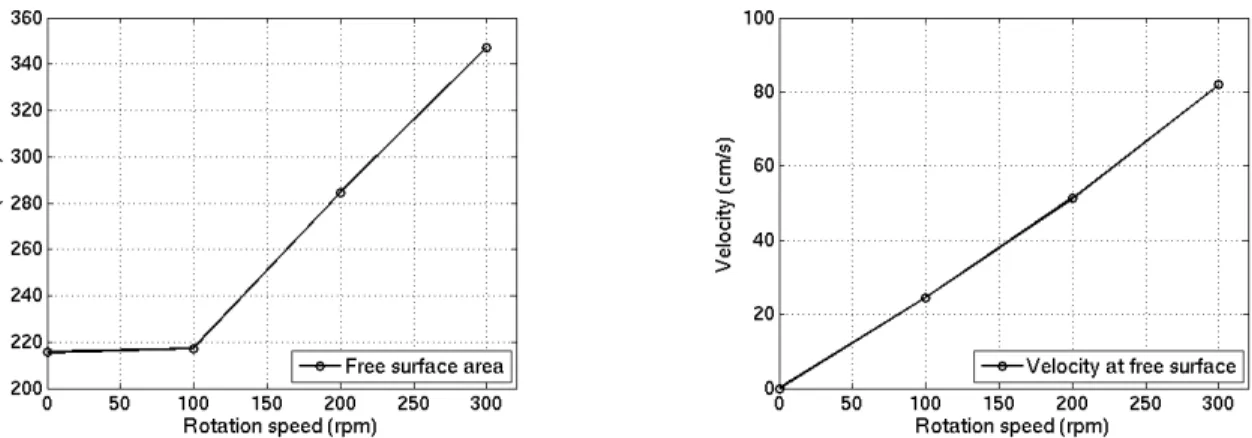
Figure 2.2-2: Free surface area (left) and velocity (right) in the crucible as functions of rotation rate ... 37
Figure 2.4-1: Bench scale bubbling apparatus ... 39
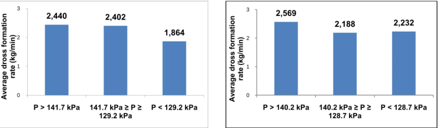
Figure 3.1-1: Effect of knife manifold pressure on dross formation rate using (a) nitrogen and (b) air for GI operation at ArcelorMittal Cleveland HDGL ... 41
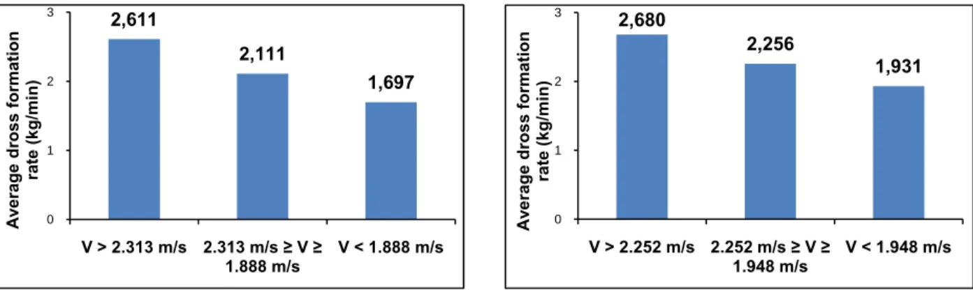
Figure 3.1-2: Effect of line speed on dross formation rate using (a) nitrogen and (b) air for GI operation at ArcelorMittal Cleveland HDGL ... 42
Figure 3.1-3: Effect of coating weight on dross formation rate using (a) nitrogen and (b) air for GI operation at ArcelorMittal Cleveland HDGL ... 42
Figure 3.1-5: Micrographs of top dross (Fe2Al5) section sampled from ArcelorMittal GI process
using nitrogen wiping ... 44
Figure 3.1-6: Micrographs of dross section with oxide films sampled from ArcelorMittal GI process using nitrogen wiping ... 45
Figure 3.1-7: Micrographs of bottom dross (FeZn10) section sampled from ArcelorMittal GA
process using nitrogen wiping ... 46
Figure 3.1-8: Micrographs of dross section with oxide films sampled from ArcelorMittal GA process using nitrogen wiping ... 47
Figure 3.1-9: Micrographs of dross section sampled from U.S.Steel Hamilton GI process using nitrogen wiping showing both bottom (FeZn10) and top dross (Fe2Al5) particles ... 48
Figure 3.1-10: Micrographs of dross section with oxide films sampled from U.S.Steel Hamilton GI process using nitrogen wiping ... 49
Figure 3.2-1: Specific rate of skimmings generation per coil vs. time at ArcelorMittal Cleveland’s HDGL ... 50
Figure 3.2-2: Cumulative specific rate of skimmings generation per coil vs. time at ArcelorMittal Cleveland’s HDGL ... 51
Figure 3.2-3: Specific rate of skimmings generation vs. impeller rotation rate for both GA and GI ... 53
Figure 3.2-4: Effect of air on the specific rate of skimmings formation for GI ... 54
Figure 3.2-5: Images of the polished sections of the skimmings samples collected in the laboratory taken by dispersive X-ray mapping ... 55
Figure 3.3-1: Operating data from ArcelorMittal Cleveland’s HDGL from October 27th to November 1st 2008 ... 57
Figure 3.3-2: Operating data from ArcelorMittal Cleveland’s HDGL from December 1st to December 4th 2008 ... 58
February 22nd 2009 ... 59
Figure 3.3-4: Operating data from ArcelorMittal Cleveland’s HDGL from March 9th to March 14th 2009 ... 60
Figure 3.3-5: Operating data from ArcelorMittal Cleveland’s HDGL from January 13th to January 15th 2009 ... 62
Figure 3.3-6: Relative variation from the mean of data from ArcelorMittal’s HDGL from October 27th to November 1st 2008 ... 65
Figure 3.3-7: Relative variation from the mean of data from ArcelorMittal’s HDGL from December 1st to December 4th 2008 ... 65
Figure 3.3-8: Relative variation from the mean of data from ArcelorMittal’s HDGL from February 18th to February 22nd 2009 ... 66
Figure 3.3-9: Relative variation from the mean of data from ArcelorMittal’s HDGL from March 9th to March 14th 2009 ... 66
Figure 3.4-1: Experimental set #1 - N2 bubbling, bath and skimmings masses ... 69
Figure 3.4-2: Experimental set #2 - N2 bubbling, bath and skimmings masses ... 70
Figure 3.4-3: Experimental set #3 - Air bubbling, bath and skimmings masses ... 71
Figure 3.4-4: Experimental set #4 - Air bubbling, bath and skimmings masses ... 72
Table 1: Common uses and attributes of coated steel sheet [3] ... 4
Table 2: Galvanneal phases and compositions [4] ... 10
Table 3: Rates of skimmings generation under air/N2 and open/shrouded conditions ... 52
Table 4: Skimmings generated using N2 and air wiping for similar conditions ... 61
Table 5: Skimmings generated using nitrogen and air wiping for different conditions ... 61
Table 6: Experimental set #1 - N2 bubbling, temperature and O2 concentration measurements ... 67
Table 7: Experimental set #2 - N2 bubbling, temperature and O2 concentration measurements ... 67
Table 8: Experimental set #3 - Air bubbling, temperature and O2 concentration measurements .. 68
Table 9: Experimental set #4 - Air bubbling, temperature and O2 concentration measurements .. 68
Table 10: Experimental set #1 - N2 bubbling, skimmings generation rate and conversion ... 69
Table 11: Experimental set#2 - N2 bubbling, skimmings generation rate and composition ... 70
Table 12: Experimental set#3 - Air bubbling, skimmings generation rate and composition ... 71
Table 13: Experimental set #4 - Air bubbling, skimmings generation rate and composition ... 72
Table 14: Experimental set #1, N2-bubbling, free surface mass transfer of Al and Fe ... 73
Table 15: Experimental set #2, N2-bubbling, free surface mass transfer of Al and Fe ... 74
Table 16: Experimental set #3, Air-bubbling, total mass transfer of Al and Fe ... 74
Table 17: Experimental set #4, Air-bubbling, total mass transfer of Al and Fe ... 75
Table 18: Experimental set #3, Air-bubbling, mass transfer of Al and Fe from air bubbles ... 76
Table 19: Experimental set #4, Air-bubbling, mass transfer of Al and Fe from air bubbles ... 76
INTRODUCTION
Since the industrial revolution, zinc has been used to improve the durability and performance of steel. Zinc coatings are valued as they provide an economical way of protecting steel against corrosion which, left unchecked, is estimated to cost an industrialized country’s economy at least 4% of GDP each year. Zinc-coated or galvanized steel combines a unique set of properties:
• high strength • formability • light weight • corrosion resistance • aesthetics • recyclability • low cost
Therefore, galvanized steel is ideally used for the manufacture of household appliances and construction materials. However, the most important product in market value is the hot-dipped galvanized or galvannealed sheet destined for auto body manufacture.
Galvanized and galvannealed steel sheets are produced in a complex metallurgical process known as the continuous hot-dip galvanizing process. Steel coils of various widths and thicknesses are unwound and continuously coated by rapid immersion in a zinc alloy bath operating at temperatures normally between 450°C and 480°C. One of the major concerns affecting the coating process is the melt loss. Usable zinc is wasted in the process and forms metallic foam which is periodically skimmed off the surface of the bath as it accumulates along the pot walls. Hence, this waste is known as skimmings and it pollutes the bath surface and impedes on the final product quality.
The work presented here is a comprehensive study of the mechanism of skimmings formation and its characterization. The work is part of a project sponsored by the International Lead and Zinc Research Organization (ILZRO) entitled ZCO-55: “Minimization of skimmings formation
the interaction of the gas jet from the wiping knives on the return flow of the zinc to the bath along the emerging strip. This interaction results in the partial loss of metal from the descending zinc flow which contributes to the skimmings that collects at the bath surface.
Two sponsors of project ZCO-55 accepted to participate in this study; ArcelorMittal Cleveland and U.S. Steel Hamilton. Both sponsors contributed skimmings samples from their respective continuous galvanizing lines in order to investigate their composition and morphology. Furthermore, only ArcelorMittal provided spread sheets of their operating data. The data was recorded at the plant from October 2008 to March 2009 but was not continuous. Pockets of information lasting approximately one to four days at a time were investigated and treated in order to determine which process parameters had the greatest effect on skimmings generation.
Two different bench scale experiments were also conducted as part of satisfying the mandate of the project. The first experiment involved simulating skimmings formation at the strip exit region of a galvanizing bath using a shrouded crucible loaded with liquid zinc, a steel impeller for agitation and an impinging jet of gas. The second experiment involved trying to simulate the mass transfer between the return zinc flow from the wiping knives and the surrounding atmosphere near the strip exit region of a galvanizing bath. This was accomplished by top submerging a jet of air into a crucible loaded with liquid zinc.
CHAPTER 1
LITTERATURE REVIEW
1.1 Overview of zinc coated steel products
There are approximately 550 continuous galvanizing lines worldwide producing almost 100 million tonnes of coated steel [1]. Nearly 75% of all galvanized sheet steel is destined for auto body manufacture and the remaining 25% is used for the construction and domestic appliance industries. There are several zinc coated steel sheet products: Galvanized (GI), Galvanneal (GA), Electrogalvanized, Galvalume® and Galfan®. The combined worldwide production of electrogalvanized, Galvalume and Galfan products pales in comparison to the combined production of galvanized and galvannealed products. A comparative analysis is shown in Figure 1.1-1 [1].
Figure 1.1-1: Continuous zinc coatings and yearly production in millions of tonnes of steel [1]
In 2007 [2] there were 10 continuous galvanizing lines in Canada, 10 in Mexico and 67 in the United States. The total GI and GA output of all 87 continuous galvanizing lines in North America and Mexico was 27.1 million tonnes. Moreover, there are 13 electrogalvanizing lines in
1 4
7
15
44
the United States and they have a total output of 3.3 million tonnes. Electrogalvanized products are essentially steel sheets electroplated with pure zinc although Zn-Fe and Zn-Ni alloy coatings are also commercialized. Unfortunately, electrogalvanized steel sheets are expensive to produce and their manufacture is slowly being phased out by the increased usage of galvannealed sheets. Galvalume coatings are 55 wt% Al-Zn alloys and provide excellent corrosion resistance wherever applications with severe forming are absent. Galfan coatings are 5 wt% Al-Zn alloys but unlike Galvalume coatings, they provide exceptional corrosion resistance wherever applications with severe forming are present. The bulk of zinc coated steel production is galvanized sheet which is produced using a liquid zinc bath containing about 0.16 wt% to 0.20 wt% Al. Similarly, galvanneal sheet is produced in the same manner except the zinc bath has an Al content ranging between 0.11 wt% and 0.14 wt% Al. Table 1 [3] summarizes the applications and key characteristics of each coating type.
Table 1: Common uses and attributes of coated steel sheet [3]
Coating Type Applications Key Attributes
Galvanized Steel framing Heating, ventilation, AC Corrugated culverts Roof and floor decking Pre‐painted building panels Agricultural storage bins Auto body inner panels High formability and durability Large range of coating weights High strength Paintability Cost effective Electrogalvanized Auto body outer panels Computer cases Ultra‐smooth surface finish Good weldability Galvanneal Auto body outer panels Pre‐painted appliance wrappers Good weldability Good paintability and formability Galvalume Bare and painted roofing and siding High temperature applications Great corrosion performance Good paintability Galfan Pre‐painted architectural panels Automotive equipment Great corrosion performance Great formability and Paintability
1.2
Description of the continuous galvanizing processContinuous hot-dip galvanizing is a process which involves the nonstop application of a molten zinc alloy coating onto the surface of steel sheets. The steel sheet is passed as a continuous ribbon through a bath of molten metal at speeds ranging between 1 m/s to 2 m/s. In the bath, the steel strip reacts with the molten zinc alloy to form a protective coating on the strip surface. The bath operating temperature usually ranges between 450 °C to 480 °C. As the strip emerges from the molten bath, it drags out excess liquid metal along with it. Using a gas-wiping process, the excess liquid dragged up with the steel sheet is pushed back into the molten bath. Moreover, the final coating thickness, also known as the deposition rate, is controlled by the gas-wiping process and is usually expressed as mass of coating per unit area of sheet (g/m2).
A typical modern day galvanizing line is illustrated in Figure 1.2-1 [3]. In the entry section, the sheet of cold rolled steel is uncoiled and welded to the tail end of the coil ahead of it in the processing line. Then, in the pre-treatment section, the strip is cleaned by brushing its surface with an alkaline liquid. After, the strip is rinsed and dried.
Figure 1.2-1: Typical modern galvanizing line for automotive product (POSCO-MEXICO) [3]
From the cleaning section, the strip enters the central part of the process. First, the strip passes into an annealing furnace where it is softened and the desired strength and formability are imparted to the steel. Furthermore, in the annealing furnace, the strip is maintained under a reducing gas atmosphere to convert any iron oxide to iron on the steel surface. The gas
atmosphere is generally composed of a mixture of 5% hydrogen and 95% nitrogen [4]. This oxide reduction step is vital to promoting the complete wetting of the strip surface during the time it is immersed in the zinc bath. Upon leaving the annealing furnace, the steel strip is normally at 460 °C which is about the same temperature as the molten zinc bath. The exit end of the annealing furnace is connected directly to the bath by a snout. The snout serves to prevent any air from re-oxidizing the heated steel strip before it enters the bath. In the bath, the strip passes around the sink roll and reacts with the molten zinc alloy to form the protective coating. The strip then exits vertically from the bath between two asymmetrically located guide and stabilizing rolls. The bath temperature is maintained by induction heaters which are generally located on both sides of the pot. They provide enough heat to overcome the heat losses at the bath surface and to melt makeup ingots. The pot configuration is shown in detail in Figure 1.2-2 [5].
Figure 1.2-2: Schematic of the top and side view of a galvanizing bath with ingot charging [5]
As the strip emerges from the bath, excess liquid zinc is dragged up along with it. The excess zinc is deflected back to the bath by the gas-wiping knives which are located on both sides of the exiting strip. The typical wiping knives configuration is shown in Figure 1.2-3 [6].
Figure 1.2-3: Typical wiping knives configuration located above the molten zinc pot [6]
The gas-wiping knives, also known as air knives, launch high pressure jets of either air or nitrogen through a narrow slit towards the strip in order to control the coating thickness. The product is then cooled to allow the coating to solidify on the steel surface. To accomplish this, the strip travels along a vertical section above the bath which can be as high as 60 m [4]. After cooling to room temperature, the strip feeds into a temper mill to impart the desired surface finish to the coated steel. Then it travels to the tension leveller which flattens the strip. Finally, the post-treatment section applies a clear water-based post-treatment and/or oil to assist with preventing degradation of the final coated product. The clear treatment prevents storage stains that can form on the coating surface when moisture is present and the oil serves to inhibit rusting [4]. A recoiler rewinds the finished coil of steel which is then sheared at the weld that was made at the entry end of the line in order to preserve coil-to-coil identity. Not all hot-dip coating lines have all of the above processing steps [4]. For example, some do not include the aqueous cleaning stage, relying instead on “flame” cleaning in the entry end of the annealing furnace. Others might not have a temper mill as it might not be necessary for some applications of hot-dip coated products.
1.3 Difference between galvanizing and galvannealing
The two main differences between galvanneal and galvanize are that galvannealed steel strips pass through zinc alloy baths that are less rich in aluminum and they are heated instead of cooled once they pass the wiping knives. Typically, galvanneal baths have aluminum concentrations ranging between 0.11 wt% to 0.14 wt% while galvanize baths have aluminum concentrations ranging between 16 wt% to 20 wt%. As shown in Figure 1.3-1 [4], once the steel strip passes the wiping knives, for a galvannealing process, it is heated in a galvanneal furnace to temperatures ranging between 500 °C to 565 °C [4] and held at that temperature for approximately 10 seconds [4]. In both galvanneal and galvanize operations, dissolved aluminum preferentially reacts with the steel to form an inhibition layer of Fe2Al5.
Zinc protective coatings vary in thickness from 10 µm to 15 µm and they consist of an inhibition layer with a thickness of about 100 nm covered by a Zn-Al alloy. In the galvanneal process, the reaction continues as the strip passes through the galvanneal furnace to form adherent layers of intermetallic Al-Fe-Zn compounds. The end result is that the coating is converted to layers of intermetallic Zn-Fe compounds. The iron content in the coating varies with its thickness, from as low as ~6 wt% at the surface, to as high as ~23 wt% at the steel interface [4]. The final bulk iron concentration depends mostly on the heating cycle since the rate of diffusion is primarily a function of time and temperature. A galvanize coating is essentially pure zinc containing between 0.20 wt% and 0.50 wt% bulk aluminum [4]. However, the aluminum in the coating is highly concentrated in the thin inhibition layer next to the steel. Cross sections of both galvanized and galvanneal steel sheets are shown in Figure 1.3-2.
Figure 1.3-1: Schematic of the molten bath, wiping knives and galvannealing furnace [4]
Galvanneal coatings typically have 3 distinct Zn-Fe phases. These phases are shown in Table 2 [4], along with their iron and aluminum contents. The phases in Table 2 are shown in the order that they occur in the coating, with the high-iron Fe3Zn10 (Γ) layer next to the steel substrate.
Table 2: Galvanneal phases and compositions [4]
Alloy Layer wt% Fe wt% Al
FeZn13 (ζ) 5.2 – 6.1 0.7
FeZn10 (δ) 7.0 – 11.5 3.7
Fe3Zn10 (Γ) 15.8 – 27.7 1.4
1.4 Zn-Fe-Al alloys and dross particles
Isolated intermetallic particles form in the bath during continuous hot-dip galvanizing. These intermetallic compounds are also known as dross. Dross normally consists of Al bearing Zn-Fe intermetallics (bottom dross) or Zn bearing Fe-Al intermetallics (top dross). The origin of these particles is a direct consequence of iron being continuously dissolved into solution during hot-dipping. Any iron in excess of the solution’s solubility limit is converted into dross particles at the bath/steel interface [8]. Thereafter, dross particles continue to precipitate from the melt during normal operation of the galvanizing line [9, 10, 11].
Top dross, Fe2Al5Znx (η phase), is primarily formed during GI operation. These particles float to
the surface of the bath since the particles are less dense than the zinc solution. Bottom dross, FeZn10Aly (δ phase), is mainly formed during GA operation. These particles sink to the bottom of
the bath since they are denser than the zinc solution. However, it is common to have both η and δ intermetallic particles form during GI operations. Figure 1.4-1 shows the particles that form in molten Zn-Fe-Al alloys found in typical galvanizing baths.
Figure 1.4-1: Typical intermetallic particles formed in molten Zn-Al-Fe alloys. Coexistent δ and η particles (left); η is darker. Collection of ζ particles (right) [12]
Continuous hot-dip galvanizing is rarely, if ever, an equilibrium process. Constant fluctuations in temperature, aluminum and iron levels in different discrete regions of the bath prevent the hot-dipping solution from attaining chemical equilibrium. Nevertheless, Zn-Fe-Al equilibrium phase diagrams have been developed in order to better understand the conditions, albeit at equilibrium, at which top and bottom dross particles form. An optimized ternary phase diagram is shown is shown in Figure 1.4-2 [13]; however, it is the Zn-rich corner of the diagram, shown in Figure 1.4-3 [14], which defines the equilibrium solubility of Fe and Al in liquid Zn that most closely represents the actual galvanizing process. Therefore, for a galvanizing bath that has achieved chemical equilibrium at 460 °C, the η, δ and liquid phases would all coexist at an aluminum level of approximately 0.135 wt%. Below this aluminum concentration, the δ phase precipitates out of solution. The η phase precipitates from solution when the bath operates at an aluminum concentration above 0.135 wt%.
Figure 1.4-2: Isothermal section of the Zn-Fe-Al system at 450°C [13]
1.5 Galvanizing bath fluid flow
A comprehensive study for a fluid flow model for continuous galvanizing was first reported in 1992 [16]. A half scale water model of a typical industrial bath was constructed of Plexiglas with a circulating rubber belt to simulate the movement of the steel strip. Flow patterns within the bath were observed by tracking the movement of polymeric particles with a video camera. The analysis of the filmed results produced the general flow pattern seen in Figure 1.5-1 [16].
Figure 1.5-1: Experimentally determined velocity profiles using 1/2 scale water model [16]
Moreover, in the same study [16], the authors attempted to mathematically model the flow field inside the water bath. As a first attempt, they used the Navier-Stokes and continuity equations. They assumed steady isothermal incompressible laminar flow and took into account only viscous, pressure and gravity forces. Finally, the physical properties of the fluid were specified using the Boussinesq approximation. The authors concluded that the measurements of the velocities in the water bath were in good agreement with the calculated values from the mathematical model. Models which numerically simulate flow in a galvanizing bath have since become progressively more complex. A solution for turbulent flow in a thermal field was presented in 2001 [17] and the case of turbulent flow in a thermal and concentration field was published in 2004 [18, 19]. It was shown that compared to the isothermal condition, the temperature gradients in the bath during ingot melting had a significant effect on the flow due to the buoyancy of the fluid. The amount of
this variation is due to the effect of temperature and concentration on the density of the bath fluid. The results from the 2004 study are presented below. Figure 1.5-2 [18] shows the calculated velocity vectors in a plane parallel to the symmetry plane with and without ingot melting.
Figure 1.5-2: Velocity profile along the symmetry plane: with (left) and without (right) ingot [18]
Figure 1.5-3 [19] shows the temperature profile along the symmetry plane. With the ingot present, the cold zinc melting from the ingot flows to the bottom of the bath.
Figure 1.5-3: Temperature distribution along the symmetry plane: (left) with ingot (t = 10 minutes) and (right) no ingot (t = 60 minutes) [19]
Figure 1.5-4 [19] illustrates the distribution of aluminum concentration on the symmetry plane. With the ingot present, we observe a higher level of aluminum near the melting ingot. When no ingot is present, the bath aluminum concentration is relatively uniform throughout the bath.
Figure 1.5-4: Aluminum concentration on the symmetry plane: (left) no ingot (t = 20 minutes) and (right) with ingot (t = 60 minutes) [19]
Similar results are shown in Figure 1.5-5 [19] for the iron concentration. The region below the melting ingot has a lower iron concentration because the ingot has no iron. When the ingot is absent, the bath iron content is relatively uniform.
Figure 1.5-5: Iron concentration on the symmetry plane: (left) no ingot (t = 20 minutes) and (right) with ingot (t = 60 minutes) [19]
Even though the numerical simulation takes into account the variation in boundary conditions, solubility limit and changes in physical properties such as the buoyancy effect, validation of the numerical model is difficult to carry out in an industrial bath. Therefore, a 1/5 scale water model shown in Figure 1.5-6 was also used to validate the numerical simulation in a galvanizing bath for isothermal and non isothermal conditions [20]. Experiments were conducted to measure the variation of temperature as a function of time for the case of cold ingot immersion. Turbulent flow was quantified using a Particle Image Velocimetry (PIV) system and the transient temperature within the bath was measured over a period of time. The experimental set up is also shown in Figure 1.5-6. The PIV system consists of a computer coupled to a camera that focuses on the bath that is illuminated by a laser light. Glass beads 10 µm in diameter were added to the water to visualize the fluid movement. Time increments between images were set to monitor the displacement and the turbulence of the liquid. The variation of temperature with respect to time was monitored at about 20 locations in the bath. The comparison of the velocity field in the vertical symmetry plane is shown in Figure 1.5-7. It was confirmed that the flow patterns calculated numerically compare very favourably with the PIV measurements.
Figure 1.5-6: (left) Photograph of 1/5 scale water model and (right) Set-up of PIV system for monitoring fluid velocity in model bath [20]
Figure 1.5-7: Comparison of the numerical simulation and PIV measurements from the water bath [20]
With the development of technology such as Laser Breakdown Induced Spectroscopy (LIBS), the continuous monitoring of Al and Fe in a galvanizing bath can be achieved. And in 2005 [21], a more precise validation study of the numerical simulation of the transient temperature and concentration distributions in the Serevco galvanizing bath was conducted. LIBS [22] is an analytical technique for the continuous element analysis of liquids, solids and gases. A high power pulsed laser vaporizes and ionizes a small volume (10-8 cm3 – 10-6 cm3) of material to produce plasma. The optical emission from this plasma is representative of the material ablated and is spectrally analyzed to obtain its atomic composition. The temperature, Al and Fe content of the Serevco bath was measured in time with both the Teck Cominco and LIBS monitoring systems. Data recording lasted 36 hours and covered the entire transition of a GA to a GI bath.
Figure 1.5-8, Figure 1.5-9 and Figure 1.5-10 show the excellent agreement between the numerical solution of the flow model and the experimental data [21].
Figure 1.5-8: Comparing simulated and measured temperatures using two thermocouples [21]
Figure 1.5-10: Comparing simulated and measured Fe concentration [21]
Figure 1.5-11 [21] illustrates the temperature distribution simulated by the numerical solution of the flow model before, during and after ingot melting. The temperature decreases during ingot melting and lower temperatures are observed around the ingot, at the bottom of the bath, on the ingot side and near the top surface in the strip exit region.
Figure 1.5-11: Temperature distribution during ingot melting at the Serevco galvanizing line [21]
Figure 1.5-12 [21] and Figure 1.5-13 [21] show the Al and Fe distributions in the bath predicted by the model. These pictures provide valuable information concerning the amount of solutes in solution and the precipitation of dross particles during ingot melting which would otherwise be impossible to see. In Figure 1.5-12, the Al distribution in the bath as a total, in solution and in precipitated form are shown before, during and after the blue ingot (4.5 wt% Al-Zn) melting period. During ingot melting, the model showed a significant increase of total Al in the bath with higher Al concentrations near the lower part of the bath at the ingot side. In this region, the Al in precipitated form also increased significantly. Also, we can observe that the regions with lower Al content are located around the entry of the strip and top of the sink roll because Al is being consumed to form the inhibition layer. In Figure 1.5-13, the Fe distribution in the bath as a total, in solution, and in precipitated form are shown before, during and after blue ingot immersion. The total Fe concentration decreases slightly during ingot melting periods whereas the precipitated Fe increases especially near the lower region of the bath at the ingot side. In this region, the Fe in solution decreases significantly as expected. Therefore, the numerical model predicts the sharp decrease of Fe in solution when the ingot is immersed. This is explained by the precipitation of dross particles as a result of a significant increase in Al in the bath and a decrease in the temperature. Moreover, the model also predicts that the quantity of Fe in solution increases
during the periods where no ingot is melting. This is caused by the dissolution of dross particles as a result of higher temperature and lower total Al in the bath.
1.6 Bath pollution: scum and skimmings
For all continuous hot-dip galvanizing lines, a portion of the excess zinc which is deflected back into the bath by the wiping knives is wasted. This waste remains afloat and pollutes the bath surface, it is known as skimmings since it is manually or robotically skimmed off the surface of the bath as it builds up along the pot walls. Skimmings production is shown in more detail in Figure 1.6-1 [23].
Figure 1.6-1: Scum build up along galvanizing pot walls [23]
In general, as seen in Figure 1.6-2 [23] skimming are a porous mixture of bath liquid, oxides and dross particles. The intense bath mixing at the strip exit region blends these components together to form metallic foam on the bath surface. The turbulent flow at the strip exit region of the bath is shown in Figure 1.6-3 [23]. Top and bottom dross particles continuously circulate inside the bath as steel is fed through it. But top dross (Fe2Al5Znx) has a tendency to float to the surface and
Figure 1.6-2: Cross sectional electron micrograph of an industrial skimmings sample [23]
Figure 1.6-3: Turbulent flow regime near the strip exit [23]
Oxides of zinc, aluminum and iron form wherever the bath liquid is exposed to air. However, it is clear that most of the oxidized metal is produced by the wiping knives especially when the wiping gas is air. A detailed flow profile of the liquid zinc flow near the wiping knives is shown in Figure 1.6-4 [24].
Figure 1.6-4: Detailed flow profile of liquid zinc near the wiping knives [24]
Galvanizers tend to us terms such as skimmings and scum to differentiate between high and low porosity metallic foam that floats on the bath surface. Scum is essential the freshly formed metallic foam that is found near the strip exit region of the bath surface. The wiping gas and the return zinc flow push the scum towards the bath edges. As the scum travels, it sweeps away the oxide layer on the bath surface along with some liquid zinc as well. It then piles up along the bath walls and further oxidizes to form skimmings. Industrial results have previously shown that scum is less porous then skimmings and that the porosities found in scum are smaller than those found in skimmings. This can be seen in Figures 1.6-5 [23] and 1.6-6 [23].
Figure 1.6-5: Cross section of scum sample. Microscope image (left) and black and white treatment (right); porosities are in white [23]
Figure 1.6-6: Cross section of skimmings sample. Microscope image (left) and black and white treatment (right); porosities are in white [23]
Statistical analyses of process parameters have shown that the wiping pressure, wiping knife height, line speed and strip width all have the greatest impact on skimmings formation [23]. It is important to note that process parameters such as the bath temperature, strip entry temperature and bath chemical composition have a greater effect on dross formation than skimmings formation. Therefore, the fluid dynamics of the liquid zinc at the strip exit region is of critical importance in understanding the mechanism of the air-zinc interaction which is the source of skimmings and scum formation.
1.7 Bubble-metal interaction
The oxidation of bath liquid observed in continuous galvanizing does not take place in a closed thermodynamic system. Moreover, as mentioned before, it is difficult to achieve chemical equilibrium in an industrial galvanizing bath. Therefore, it is reasonable to assume that the oxidation of liquid zinc alloy will not produce an equilibrium mixture of complex slags of O, Zn, Fe and Al. Instead, this work assumes that the formation of oxides is driven by the following one-way chemical reactions:
1
2
2 3 2
2 3 2
The present work attempts to simulate the oxidation in continuous galvanizing by bubbling air through a liquid zinc alloy solution. In metallurgical processes, bubbles bring about mass transfer by either giving or taking some element to or from the melt. Generally, these reactions take place in the metallic phase. There is considerable literature on the behaviour and reaction of bubbles in liquids at room temperature. However, literature on high temperature liquid metals is very limited. This is attributed to the fact that metallic solutions are opaque and make visual examination of the bubbles impossible. Moreover, difficulties with high temperature experimentation also impedes on any progress concerning bubble-metal interactions. Of particular importance to the author is the estimation of bubble size and shape for a given orifice diameter and flow rate and the experimental determination of mass transfer coefficients for interactions between bubbles and liquid metals. Some researchers have shown that the behaviour of gas bubbles in liquid metals is similar to that of the bubbles in low temperature liquids under certain conditions [25, 26] such as low bubble velocities, small bubble sizes and a laminar flow regime of the liquid phase. The correlations used to estimate bubble size and velocity will be presented below.
1.8 Bubble size
Leibson et al. [27] studied the mechanics of bubble formation in the air-water system and showed that the bubble diameter was heavily influenced by the orifice diameter and Reynolds number. The orifice Reynolds number is given by:
Where do is the orifice diameter, vg is the average gas velocity at the orifice and ρg and μg are, respectively, the gas density and viscosity. In the laminar flow regime, Reo ≤ 2000, uniformly sized bubbles are formed at the orifice and, if large enough, may coalesce or shatter into bigger or smaller bubbles some distance away. In the turbulent flow regime, Reo ≥ 10000, large irregular bubbles are formed at the orifice and they explode some distance away into smaller members to form a characteristic jet cone. The bubble diameter for each flow regime is given by:
: 0.287 / /
: 0.71 /
Where db is the bubble diameter and along with do is expressed in centimetres. These empirical equations indicate that the bubble size is only a function of the physical system. Therefore, it appears reasonable to directly apply these air-water formulae to gas-metal systems.
1.9 Bubble velocity
Very small spherical bubbles, rising in liquids containing surface active agents, do not exhibit internal circulation. Internal circulation ceases as the surface active agents form an immobile film
on the bubble surface. Hence, the bubbles behave as rigid spheres and their terminal velocity is given by Stokes’ Law:
2 9
Where U∞ is the bubble terminal velocity, g is gravity, rb is the bubble radius, ρl and μl are, respectively, the liquid density and viscosity and ρg is the gas density. This expression is valid for systems where steady creeping flow around the bubble can be assumed. The author believes that the bubbles issued from the orifice will not be very small i.e. millimetre scale or less. Moreover, assuming steady creeping flow is a poor description of the process in question. Therefore, this classic expression was deemed inadequate for the present work. As bubbles increase in size their spherical shape becomes distorted and surface active agents can no longer halt internal circulation. Assuming the shape of the bubble resembles to a spherical cap, Davies and Taylor [28] have shown that potential flow can be assumed around the bubble. Based on those results, Collins [29] had developed an expression for the terminal velocity of a rising bubble:
1
2
1.10 Gas-liquid mass transfer
Mass transfer between the bubble and the surrounding liquid was modelled using the Lewis-Whitman two-film theory. This model proposes that the rate of solute transfer happens across two stagnant films that are adjacent to a common interface. A physical representation of the model is shown in Figure 1.10-1.
Figure 1.10-1: Concentration profiles for Fe and Al transferring between liquid metal and gas
The model assumes chemical equilibrium at the interface and steady-state diffusion across the two stagnant films. For the present work, the solvent is zinc and the solutes of interest are aluminum and iron. Therefore, from the two film model, assuming both gas and liquid phases are well mixed then the fluxes of aluminum and iron in the liquid film can be written as:
, , , , , , , , , , , , , ,
Where NAl and NFe are the fluxes of aluminum and iron, CBAl,l, CBAl,g, CBFe,l, CBFe,g are the bulk aluminum and iron concentrations in the liquid and gas phases, C*Al,l, C*Al,g, C*Fe,l, C*Fe,g are the interfacial concentrations of aluminum and iron on the liquid and gas sides on the interface and kAl,l, kAl,g, kFe,l, kFe,g are the mass transfer coefficients for aluminum and iron across both the liquid
CB Al, Fe (l) CB Al, Fe (g) C* Al, Fe (g) C* Al, Fe (l)
and gas films. Furthermore, it is reasonable to say that both aluminum and iron immediately react with oxygen once they diffuse to the liquid side of the interface. Then, it follows that C*Al,l = C*
Fe,l ≈ 0. The flux equations above now are simplified to:
1 , , , , 1 , , , ,
These relationships are what should be expected from the system provided that the interfacial concentrations of aluminum and iron are almost zero. In other words, the mass transfer of solutes is controlled by their rates of diffusion through the liquid film.
![Figure 1.1-1: Continuous zinc coatings and yearly production in millions of tonnes of steel [1]](https://thumb-eu.123doks.com/thumbv2/123doknet/2334469.32476/25.918.190.737.545.876/figure-continuous-coatings-yearly-production-millions-tonnes-steel.webp)
![Figure 1.2-2: Schematic of the top and side view of a galvanizing bath with ingot charging [5]](https://thumb-eu.123doks.com/thumbv2/123doknet/2334469.32476/28.918.146.793.532.796/figure-schematic-view-galvanizing-bath-ingot-charging.webp)
![Figure 1.3-1: Schematic of the molten bath, wiping knives and galvannealing furnace [4]](https://thumb-eu.123doks.com/thumbv2/123doknet/2334469.32476/31.918.231.693.125.671/figure-schematic-molten-bath-wiping-knives-galvannealing-furnace.webp)
![Figure 1.4-3: Zinc rich corner of the Zn-Fe-Al system [14] with experimental data points [15]](https://thumb-eu.123doks.com/thumbv2/123doknet/2334469.32476/34.918.200.689.671.1031/figure-zinc-rich-corner-zn-experimental-data-points.webp)
![Figure 1.5-7: Comparison of the numerical simulation and PIV measurements from the water bath [20]](https://thumb-eu.123doks.com/thumbv2/123doknet/2334469.32476/39.918.138.783.140.616/figure-comparison-numerical-simulation-piv-measurements-water-bath.webp)
![Figure 1.5-12: Mathematical model predictions of Al distribution during ingot melting [21]](https://thumb-eu.123doks.com/thumbv2/123doknet/2334469.32476/43.918.105.814.210.1032/figure-mathematical-model-predictions-al-distribution-ingot-melting.webp)
![Figure 1.6-2: Cross sectional electron micrograph of an industrial skimmings sample [23]](https://thumb-eu.123doks.com/thumbv2/123doknet/2334469.32476/46.918.207.717.144.381/figure-cross-sectional-electron-micrograph-industrial-skimmings-sample.webp)