POLYTECHNIQUE MONTRÉAL
affiliée à l’Université de Montréal
Biomechanical Modeling of Transforaminal Lumbar Interbody Fusion: a
Comparative Assessment of Segmental Lumbar Lordosis and Risk of Cage
Subsidence With Different Cage Heights and Placements
SAJJAD RASTEGAR TALZALI Département de génie mécanique
Mémoire présenté en vue de l’obtention du diplôme de Maîtrise ès sciences appliquées Génie mécanique
Mai 2019
POLYTECHNIQUE MONTRÉAL
affiliée à l’Université de Montréal
Ce mémoire intitulé :
Biomechanical Modeling of Transforaminal Lumbar Interbody Fusion: a
Comparative Assessment of Segmental Lumbar Lordosis and Risk of Cage
Subsidence With Different Cage Heights and Placements
présenté par Sajjad RASTEGAR TALZALI
en vue de l’obtention du diplôme de Maîtrise ès sciences appliquées a été dûment accepté par le jury d’examen constitué de :
Isabelle VILLEMURE, présidente
Carl-Éric AUBIN, membre et directeur de recherche
Pierre-Jean ARNOUX, membre et codirecteur de recherche Yvan PETIT, membre
DEDICATION
To my parents and my lovely wife Mahsa,
ACKNOWLEDGEMENTS
I would like to give my special and sincere gratitude to my advisor Prof. Carl-Éric Aubin for the continuous support of my project. Prof. Aubin’s patience, motivation, extended expertise, and immense knowledge, altogether, were the important factors for guiding this research project. His attitude of gratitude through this work not only highly elevated my research expertise, but also shaped my personal and professional level.
I also would like to thank Dr. Pierre-Jean Arnoux, my research co-director, for his insightful comments and encouragement during this project. His wide overview always equipped me with the questions that allowed me to widen the horizons of the project.
Additionally, I would like to offer my gratitude to my lab colleagues for the stimulating and constructive discussions, team-work, generous supports, and cherished memories I had with them. In particular, I thank my friends Dr. Leo Fradet and Dr. Rohan-Jean Bianco for enlightening me to better grab the conducted research niche and using the Altair Hyperworks.
I also would like to appreciate the Natural Sciences and Engineering Research Council of Canada and Medtronic of Canada, for the financial support that allowed me to realize this research work. Last but not the least, I must give my best profound gratitude to my parents and my wife Mahsa for their unconditional and unfailing supports, and continuous encouragement throughout my life, especially in this project. I could not have made this accomplishment without your spiritual support. I wish I could find a word to thank you enough. I truly love you!
RÉSUMÉ
Les affections pathologiques du rachis lombaire telles que les discopathies dégénératives, les spondylolisthésis ou les hernies discales récurrentes sont connues pour produire des douleurs lombaires et peuvent nécessiter une instrumentation et fusion du rachis dans les cas les plus sévères. La fusion lombaire à l’aide d’un implant intersomatique par voie transforaminale (transforaminal lumbar interbody fusion ou TLIF) est une technique chirurgicale visant à restaurer la hauteur du corps intervertébral, la lordose lombaire segmentaire (SLL), et à accroître la stabilité de la colonne lombaire. La procédure standard implique l'ablation du noyau pulpeux (NP) et d'une partie de l'anneau de cartilage fibreux (AF), suivie de la décompression du segment et de l'insertion d’une cage intersomatique dans l'espace intervertébral par une approche médiolatérale. L'instrumentation postérieure vise en outre à stabiliser et permettre une fusion solide du segment rachidien.
L'une des défaillances mécaniques du TLIF, qui menace le succès de la fusion, est l'affaissement des vertèbres au niveau de la cage et la perte associée de la hauteur du corps vertébral, avec une incidence rapportée entre 8.6 % et 38.1 %. Cet affaissement survient lorsqu’un plateau du corps vertébral ne peut résister aux forces transférées à l’interface plateau vertébral/cage. Bien que des études cliniques, des études expérimentales sur cadavres et des analyses numériques aient été réalisées sur l'utilisation de différentes formes, dimensions, configurations et hauteurs de cage, le rôle des paramètres essentiels de la cage, à savoir sa hauteur et sa position, en lien avec le risque de l'affaissement des plateaux vertébraux n'est pas entièrement compris biomécaniquement. L’objectif de ce mémoire était de comparer biomécaniquement les variations angulaires de lordose segmentaire et les risques d’affaissement en utilisant des cages intersomatiques pour différentes hauteurs et positions de cage, ainsi que pour différentes qualités de l'os.
Pour répondre à l'objectif susmentionné, un modèle détaillé par éléments finis (MEF) de l'unité fonctionnelle L4-L5 a été créé sur la base du modèle SM2S (Spine Model for Safety and Surgery), précédemment développé et validé. Ce MEF est basé sur les images tomodensitométriques (épaisseur de coupe de 0.6 mm) d'un homme asymptomatique du 50e percentile. Le MEF comprend les os trabéculaires et corticaux du corps vertébral et des arcs postérieurs, le disque intervertébral, les facettes articulaires et sept ligaments. Le maillage du MEF a été réalisé et vérifié grâce à une étude de convergence et les propriétés des matériaux ont été adaptées de la littérature. L'os
ostéoporotique a été modélisé en réduisant les modules de Young des os cortical et trabéculaire de 33 % et 66 %, respectivement.
Pour simuler la procédure TLIF, on a modélisé la préparation du disque intervertébral en enlevant le NP et les éléments situés à l'arrière gauche de l'AF, puis en enlevant partiellement les éléments correspondants des facettes zygapophysaires de l'articulation. Ensuite, des vis pédiculaires multiaxiales (40 mm x 6.5 mm ; CD HORIZON® LEGACYTM ; Medtronic, USA) ont été insérées sur les deux côtés de chaque vertèbre. Ensuite, une cage (CAPSTONE® interbody cage, Medtronic Inc., Memphis, USA) a été insérée de telle sorte à s'assurer qu'il y avait un contact intime à l’interface plateau vertébral/cage. Ensuite, la fixation postérieure a été réalisée en modélisant deux tiges en titane (4.5 mm) insérées dans les têtes de vis. La surface inférieure de L5 a été immobilisée et le plateau supérieur de L4 a été soumis à une force compressive de 400N orientée selon la courbure spinale, ainsi qu’à des moments de 10 Nm en flexion, extension, flexion latérale et rotation axiale appliquées séquentiellement. Les amplitudes de mouvements et les distributions de contraintes de Von Mises aux interfaces plateau vertébral/cage ont été évaluées. Le changement de SLL après placement de la cage a été calculé comme la différence d'angle entre le plateau supérieur de L4 et le plateau inférieur de L5.
La SLL a été augmentée de 0.9° (11 %) et 1.0° (13 %), respectivement pour la cage de 8 mm en position oblique asymétrique et en position antérieure symétrique ; elle était de 1.4° (18 %) et 1.7° (21 %) en simulant avec une cage de 10 mm de hauteur. La variation de l'amplitude de mouvement après la fixation postérieure simulée était inférieure à 1° pour tous les scénarios TLIF simulés. Par rapport à la cage de 8 mm, les contraintes maximales aux interfaces plateau vertébral/cage de 10 mm étaient jusqu'à 16 % plus élevées dans les simulations avec le modèle osseux normal, comparativement à celui ostéoporotique. Les contraintes maximales pour le placement asymétrique de la cage étaient respectivement jusqu'à 41 % et 43 % plus élevées que le placement symétrique avec le modèle osseux normal vs. ostéoporotique.
Pour une qualité osseuse normale simulée, avec l'utilisation d’une cage de 8 mm, les contraintes maximales à l’interface plateau vertébral/cage variaient de 82.1 à 98.4 MPa (placement symétrique antérieur) et de 117.9 à 155.5 MPa (placement asymétrique oblique). Avec l'utilisation d'une cage de 10 mm, elles étaient de 88.2 à 107.2 MPa (placement symétrique antérieur) et entre 134.4 et 176.4 MPa (placement asymétrique oblique). Pour la simulation de l’os ostéoporotique, les
contraintes à l’interface plateau vertébral/cage étaient inférieures d'environ 2.5 %. Le placement oblique asymétrique par rapport au placement antérieur symétrique de la cage a augmenté les contraintes maximales à l’interface plateau vertébral/cage jusqu'à 41 % et 43 % respectivement pour l'os normal et l'os os ostéoporotique simulé. L'insertion de la cage de 10 mm par rapport à celle de 8 mm a augmenté les contraintes maximales à l’interface plateau vertébral/cage jusqu'à 16% pour le modèle osseux normal vs. ostéoporotique. Les contraintes dans les tiges postérieures ont augmenté jusqu'à 120% pour la simulation de l'os ostéoporotique. Le placement oblique asymétrique par rapport au placement antérieur symétrique de la cage a augmenté les contraintes maximales dans les tiges postérieures jusqu'à 55% et 48% pour l'os normal et ostéoporotique simulé, respectivement. L'insertion de la cage de 10 mm par rapport à celle de 8 mm a augmenté les contraintes maximales dans les tiges postérieures jusqu'à 59% et 54% respectivement pour le modèle osseux normal vs. ostéoporotique.
La SLL résultante était plus élevée avec la cage de 10 mm qu'avec la cage de 8 mm pour chaque stratégie de placement. La SLL simulée en placement asymétrique oblique était identique à celle du placement symétrique antérieur. Les contraintes maximales augmentaient avec le placement asymétrique oblique et l'utilisation d'une cage de 10 mm, ce qui est interprété comme favorable à l’augmentation du risque d'affaissement des plateaux vertébraux. Comme l'os ostéoporotique a des propriétés mécaniques réduites, le risque d'affaissement de la cage devrait être plus élevé. Les contraintes maximales dans les tiges postérieures étaient plus élevées en position oblique asymétrique et avec l'utilisation d'une cage de 8 mm. De plus, avec l'ostéoporose simulée, les contraintes maximales dans les tiges postérieures ont augmenté, ce qui peut impliquer un risque plus élevé de défaillance des tiges.
ABSTRACT
Pathological conditions such as degenerative disc disease, spondylolisthesis, or recurrent disc herniation are known to produce back pain and may be indications for a lumbar spinal fusion for disabling low back conditions that were unsuccessfully improved with non-surgical treatments. Transforaminal lumbar interbody fusion (TLIF) is a surgical technique to restore the intervertebral body height, the segmental lumbar lordosis (SLL), and to add stability to the lumbar spine. The standard procedure involves the removal of the nucleus pulposus (NP) and a portion of the annulus fibrosus (AF), followed by decompression of the segment and insertion of the interbody cage into the intervertebral disc space through a mediolateral approach. Posterior instrumentation additionally aims to achieve a solid fusion at the spinal segment.
Cage subsidence is one of the mechanical failures of TLIF which threatens the success of the spine fusion with a reported incidence between 8.6% and 38.1%. Cage subsidence is a situation where an endplate fails to withstand the transferred loads at the endplate-cage interface resulting in the loss of the intervertebral body height. Although clinical studies, cadaveric experimental investigations, and numerical analyses have investigated the use of different cage shapes, dimensions, configurations, and heights, the role of essential cage parameters, namely the height of cage and its placement strategy, in the risk of cage subsidence are not fully biomechanically understood. The objective of this project was to biomechanically assess the resulting SLL and stresses at the endplate-cage interface with the change of the cage height, its placement strategy, and the bone quality.
To address the aforementioned objective, a detailed finite element model (FEM) of the L4-L5 functional unit was created based on the previously developed and validated Spine Model for Safety and Surgery (SM2S) FEM. The FEM of the L4-L5 functional unit is based on the CT-scan images (0.6 mm slice thickness) of a 50th percentile asymptomatic man. The FEM includes trabecular and cortical bones of the vertebral body and of the posterior processes, the intervertebral disc, the facet joints, and seven ligaments. The FEM was properly meshed and refined through a convergence study and material properties were adapted from the literature. Osteoporosis was modeled by reducing the Young’s modulus of the cortical and trabecular bones by 33% and 66%, respectively.
To simulate the TLIF procedure, intervertebral disc preparation was modeled by removing the NP and elements at the posterior-left of the AF followed by partial removal of the corresponding elements of the zygapophyseal facet joints. Next, multiaxial pedicle screws (40 mm x 6.5 mm; CD HORIZON® LEGACYTM; Medtronic, USA) were inserted on two sides of each vertebra. Then, an available cage (CAPSTONE® interbody cage, Medtronic Inc., Memphis, USA) was inserted in such a way there was an intimate contact at the endplate-cage interface. After, the posterior fixation was performed by modeling two titanium rods (4.5 mm) aligned with the screw head saddle. The simulated TLIF model was subjected to a 400 N follower load and a 10-Nm bending moment simulating the functional loads in the three anatomical planes to mimic flexion (Fe), extension (Ex), right lateral bending (RLB), left lateral bending (LLB), right axial rotation (RAR), and left axial rotation (LAR). Two cage heights (8 and 10 mm), two placement strategies (anterior symmetric vs. oblique asymmetric) were tested for two simulated bone qualities (normal and osteoporotic). The range of motion (ROM) and maximum Von-Mises stresses at the endplate-cage interface as the predictor of the risk of cage subsidence were calculated. The change of the SLL after cage placement was calculated as the difference of angle between the superior endplate of L4 and the inferior endplate of L5.
The SLL was increased by 0.9° (11%) and 1.0° (13 %), respectively in oblique asymmetric and anterior symmetric cage placement with 8-mm cage height; they were 1.4° (18%) and 1.7° (21 %) when simulating with a 10-mm height cage. The change in the range of motion after the simulated posterior fixation was lower than 1° in all the simulated TLIF scenarios. Compared to the 8-mm cage, maximum stresses at the cage-bone interface with the 10-mm cage were up to 16% higher in simulations with both normal and osteoporotic bone models. Maximum stresses in asymmetric cage placement were respectively up to 41% and 43% higher than the symmetric placement in normal and osteoporotic bone models.
For simulated normal bone quality, with the use of 8-mm, the maximum stresses at the bone-cage interface ranged from 82.1 to 98.4 MPa (anterior symmetric placement) and from 117.9 to 155.5 MPa (oblique asymmetric placement). With the use of 10-mm cage, they were from 88.2 to 107.2 MPa (anterior symmetric placement) and between 134.4 and 176.4 MPa (oblique asymmetric placement). For the simulated osteoporosis, stresses at the bone-cage interface were about 2.5% lower. Oblique asymmetric vs. anterior symmetric cage placement increased the maximum stresses at the endplate-cage interface up to 41% and 43% for the simulated normal and osteoporotic bone,
respectively. Insertion of the 10-mm cage vs. the 8-mm one increased the maximum stresses at the endplate-cage interface up to 16% in simulated normal and osteoporotic bone models. Stresses in the posterior rods increased up to 120% with osteoporosis bone. Oblique asymmetric vs. anterior symmetric cage placement increased the maximum stresses in the posterior rods up to 55% and 48% for the simulated normal and osteoporotic bone, respectively. Insertion of the 10-mm cage vs. the 8-mm one increased the maximum stresses in the posterior rods up to 59% and 54% in simulated normal and osteoporotic bone models, respectively.
The resulting SLL was higher with the 10-mm cage vs. 8-mm in each placement strategy. The simulated SLL in oblique asymmetric placement was identical to that of anterior symmetric placement. The maximum stresses increased with the oblique asymmetric placement and the use of 10-mm cage which may increase the risk of cage subsidence. Since osteoporotic bone has compromised mechanical properties, the risk of cage subsidence should be higher though the maximum stresses at the endplate-cage interface were similar for those bone qualities. The maximum stresses in the posterior rods were higher in oblique asymmetric placement and with the use of 8-mm cage. Also, with the simulated osteoporosis, the maximum stresses in the posterior rods increased, which may imply a higher risk of failures of the rods.
TABLE OF CONTENTS
DEDICATION ... III ACKNOWLEDGEMENTS ...IV RÉSUMÉ ... V ABSTRACT ... VIII TABLE OF CONTENTS ...XI LIST OF TABLES ... XIV LIST OF FIGURES ... XV LIST OF SYMBOLS AND ABBREVIATIONS... XVIII
CHAPTER 1 INTRODUCTION ... 1
CHAPTER 2 LITERATURE REVIEW ... 4
2.1 Anatomy of human spine ... 4
2.1.1 Vertebrae ... 5
2.1.2 Intervertebral discs ... 6
2.1.3 Ligaments ... 7
2.2 Biomechanics of the asymptomatic spine... 9
2.2.1 Spinal loads ... 9
2.2.2 Spinal Motion ... 10
2.3 Spinal pathologies with the disc as the source of mechanical back pain... 12
2.4 Transforaminal lumbar interbody fusion (TLIF) ... 14
2.4.1 Description of TLIF procedures ... 15
2.4.2 Biomechanics of TLIF ... 17
2.4.3 Failure modes in TLIF... 18
2.5.1 Finite element modeling of the spine ... 21
2.5.2 Critical review of lumbar spine finite element models ... 22
2.5.3 Critical review of previous biomechanical FEM studies of TLIF ... 24
CHAPTER 3 RESEARCH RATIONALE AND OBJECTIVES ... 29
CHAPTER 4 ARTICLE I: BIOMECHANICAL ANALYSIS OF SEGMENTAL LUMBAR LORDOSIS AND RISK OF CAGE SUBSIDENCE WITH DIFFERENT CAGE HEIGHTS AND ALTERNATIVE PLACEMENTS IN TRANSFORAMINAL LUMBAR INTERBODY FUSION ... 32
4.1 Presentation of the manuscript... 32
4.2 Scientific manuscript: Biomechanical analysis of segmental lumbar lordosis and risk of cage subsidence with different cage heights and alternative placements in transforaminal lumbar interbody fusion... 32
Keywords ... 33
4.2.1 Abstract ... 33
4.2.2 Introduction ... 34
4.2.3 Methods and materials ... 35
4.2.4 Results ... 38 4.2.5 Discussion ... 39 4.2.6 Conclusion ... 41 4.2.7 Acknowledgement ... 41 4.2.8 References ... 42 4.2.9 Figures ... 45 4.2.10 Tables ... 51
CHAPTER 5 VERIFICATION, VALIDATION, AND SENSITIVITY ANALYSES ... 54
5.2 ROM of the uninstrumented model under various bending moments ... 55
5.3 Effects of the material properties of the spinal ligaments on the resulting SLL ... 56
5.4 Mesh convergence study at the endplate-cage interface... 58
5.5 Stress distribution at the endplate-cage interface ... 59
5.6 Maximum stress in the trabecular bone of the L5 vertebral body ... 61
5.7 Maximum strain at the endplate-cage interface ... 61
5.8 Effect of the interbody cage positioning on the stresses at the endplate-cage interface 62 5.9 Effect of the cortical shell thickness on the stresses at the endplate-cage interface ... 65
5.10 Effect of the friction coefficient at the endplate-cage interface ... 66
5.11 Summary ... 67
CHAPTER 6 GENERAL DISCUSSION ... 69
CHAPTER 7 CONCLUSIONS AND RECOMMENDATIONS ... 73
LIST OF TABLES
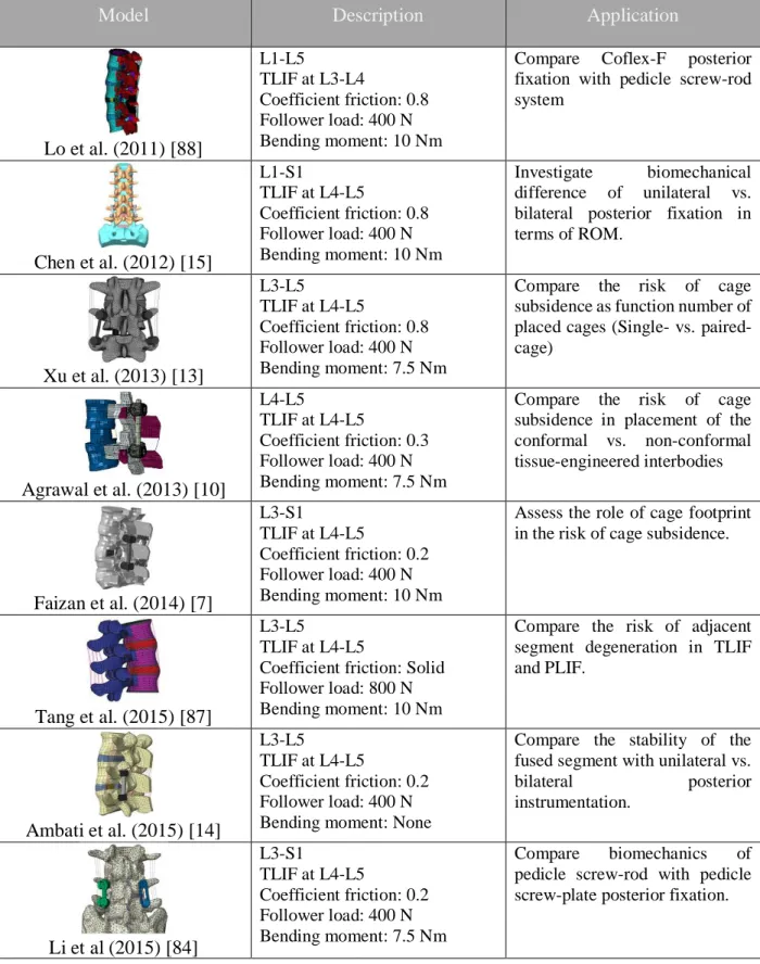
Table 2-1 Summary of the available finite element models have been used to investigate biomechanics of TLIF ... 27 Table 4-1 Material properties of bony elements of the FEM ... 57 Table 4-2 Material properties of the intervertebral disc ... 57 Table 4-3 Material properties of the ligaments (ALL: Anterior longitudinal ligament; PLL: Posterior longitudinal ligament, ITL: Intertransverse ligament, ISL: Interspinous Ligament, LF: Ligament flavum, SSL: Supraspinous ligament, and CL: Capsular ligament) ... 57 Table 5-1 The Young’s modulus (MPa) tested for the sensitivity analysis were adapted from the finite element study of Li et al. (2015) ... 57 Table 5-2 Increment of the simulated SLL with the alternate Young’s modulus’ adapted from the
finite element study of Li et al. (2015) [84] ... 57 Table 5-3 Maximum and average stresses (MPa) on the superior endplate of L5 when 10-mm
oblique asymmetrically inserted cage was shifted 1 mm to the left, right, front and back .... 64 Table 5-4 The maximum and average Von-Mises stresses distributed on the superior endplate of
L5 with two thickness of the cortical shell (0.3 and 0.4 mm) ... 65 Table 5-5 Variation of the average and maximum stresses, and tangent forces generated on the
superior endplate of L5 versus different values of friction coefficient at the endplate-cage interface ... 66 Table 5-6 Summary of the conducted tests to establish the model credibility and to identify the
LIST OF FIGURES
Figure 2-1 Natural spinal curves and different regions of the spinal column ... 5
Figure 2-2 General structure of a typical lumbar vertebra. Each vertebra has generally two particular parts including the vertebral body and posterior arches. ... 6
Figure 2-3 Structure of the intervertebral disc, A) NP and AF composed of concentric layers, B) Orientation of collagen fibers of the AF ... 7
Figure 2-4 Seven spinal ligaments ... 8
Figure 2-5 A typical load-deformation curve of a joint, e.g. between two adjacent vertebrae, has two major regions: the flexible region at low load called neutral zone (NZ); and stiff region called elastic zone (EZ). NZ and EZ together provide the range of motion (ROM) ... 10
Figure 2-6 Segmental range of motion for each motion segment in flexion-extension, side bending, and axial rotation summarized from ... 11
Figure 2-7 Each spinal segment provides six degrees of freedom (DOFs): three translations and three rotations ... 11
Figure 2-8 Classification of disc degeneration proposed by Benneker et al. (2005). From grade 1 (a) to grade 5 (e), the severity increased based on the evaluation of radiological parameters such as disc height, nucleus roundness, and colors ... 13
Figure 2-9 Common surgical fusion approaches... 14
Figure 2-10 The detailed procedure of TLIF. ... 16
Figure 2-11 The lumbar spine underwent single level TLIF ... 16
Figure 2-12 Interbody cages with different shapes and materials ... 17
Figure 2-13 Measurement of the cage subsidence from the radiological evaluation ... 20
Figure 2-14 A) Generic model with parametrized body height, width, depth, and thickness, and B) a specimen FEM of the L3 lumbar vertebra ... 21
Figure 4-1 The uninstrumented FE model of the L4-L5 segment including the vertebrae, seven spinal ligaments, and intervertebral disc. ALL: Anterior Longitudinal ligament, PLL: Posterior Longitudinal Ligament, ITL: Intertransverse Ligament, CL: Capsular Ligament, LF: Ligament Flavum, ISL: Interspinous Ligament, SSL: Supraspinous Ligament, AF: Annulus Fibrosus, NP: Nucleus Pulposus. ... 45 Figure 4-2 Regional thickness of the cortical bone and finer mesh of the trabecular bone around
the screw imprint for L5 ... 46 Figure4-3 Simulation of different surgical procedures of TLIF: (a) Partial discectomy and
facetectomy of L4-L5, (b) Cage placement by imposing distractive force and moment on L4, while the inferior endplate of L5 was fixed in space, and (c) Implementation of the posterior fixation followed by application of the follower load and physiological moments (flexion, extension, lateral bending, and torsion) on the superior endplate of L4 while the inferior endplate of L5 was fixed in space ... 47 Figure 4-4 Simulated placement scenarios of the cage: (a) Oblique asymmetric: (b) Anterior
symmetric ... 48 Figure 4-5 Maximum Von-Mises stress at the bone-cage interface in different loading directions
for normal (a) and osteoporotic (b) bone model (A08/A10: Oblique asymmetric placement of 8/10-mm cage; S08/S10: Anterior symmetric placement of 8/10-mm cage)... 49 Figure4-6 Maximum Von-Mises stress in the posterior rods in different loading directions for
normal (a) and osteoporotic (b) bone models (A08/A10: Oblique asymmetric placement of 8/10-mm cage; S08/S10: Anterior symmetric placement of 8/10-mm cage)... 50 Figure 5-1 Simulated ROM under 8 Nm bending moment in flexion-extension, lateral bending,
and axial rotation, and available measurements from experimental cadaveric tests ... 56 Figure 5-2 Cross sections of the L5 vertebral body with the element sizes of 1.5 (A), 1.0 (B), and
0.5 (C) mm. ... 58 Figure5-3 The convergence curves of the maximum stress on the superior endplate of L5 in
different loading directions. The 10-mm cage was inserted in oblique asymmetric placement, the posterior fixation was conducted, and a 400 N follower load and a 10 Nm bending moment
were applied. Fe: Flexion, Ex: Extension, RLB: Right Lateral Bending, LLB: Left Lateral bending, RAR: Right Axial Rotation, and LAR: Left Axial Rotation ... 58 Figure 5-4 Stress maps on the superior endplate of L5 with the element sizes of 1.5 (A), 1.0 (B),
and 0.5 (C) mm. The 10-mm cage was inserted in oblique asymmetric placement, the posterior instrumentation was performed, and a 400 N follower load and 10 Nm flexion moment was applied ... 59 Figure 5-5 Endplates-cage interface A) after oblique asymmetric placement of the 10-mm cage
with a fit contact, and B) when the posterior instrumentation was performed and segment was subjected to a combination of a 400 N follower load and flexion bending moment. Here, the mesh size is 1.0 mm. ... 60 Figure 5-6 A) Stresses maps on the superior endplate of L5 after oblique asymmetric placement of
the 10-mm cage, and, B) after application of the combination of the 400 N follower load and 10 Nm bending moment in flexion. ... 60 Figure 5-7 The 10-mm cage in oblique asymmetric placement was sequentially moved 1 mm to the
left (1L), right (1R), front (1F), and back (1B) of its initial position. Then, for each model, the inferior endplate of L5 was fixed, and 400 N follower load was applied to the L4 followed by the 10 Nm bending moment in the physiological planes. The maximum and average stresses on the superior endplate of L5 were calculated... 63
LIST OF SYMBOLS AND ABBREVIATIONS
ρ Density
λ0 Navier’s constant ν Poisson's ratio
νr Tangent poisson’s ratio η0 Viscosity coefficient
1F 1 mm shift in position of oblique asymmetrically placed 10-mm cage toward anterior 1L 1 mm shift in position of oblique asymmetrically placed 10-mm cage toward left 1B 1 mm shift in position of oblique asymmetrically placed 10-mm cage toward posterior 1R 1 mm shift in position of oblique asymmetrically placed 10-mm cage toward right A08 Oblique asymmetric placement of the 08-mm cage
A10 Oblique asymmetric placement of the 10-mm cage AF Annulus fibrosus
ALIF Anterior lumbar interbody fusion ALL Anterior longitudinal ligament ASD Adjacent segment degeneration CAD Computer aided design
CL Capsular ligament E Elastic modulus Ex Extension Er Tangent modulus EZ Elastic zone Fe Flexion FE Finite element
FEA Finite element analysis FEM Finite element model ILS Interspinous ligament ITL Intertransverse ligament LAR Left axial rotation LF Ligament flavum LLB Left Lateral bending NP Nucleus Pulposus
NZ Neutral zone
PLIF Posterior lumbar interbody fusion PLL Posterior longitudinal ligament RAR Right axial rotation
RLB Right lateral bending ROM Range of motion SSL Supraspinous ligament
S08 Anterior symmetric placement of the 08-mm cage S10 Anterior symmetric placement of the 10-mm cage TLIF Transforaminal lumbar interbody fusion
CHAPTER 1
INTRODUCTION
Degenerative disc diseases such as spondylolisthesis, disc herniation, and lumbar spine stenosis are known to produce low back pain. Worldwide, 266 million people (3.63%) per year suffer from low back pain, which places a burden on the socioeconomic systems [1]. Some of the pathological situations associated with low back pain may have the indications for a lumbar spinal fusion when disabling low back conditions are unsuccessfully improved with non-surgical treatments.
Transforaminal lumbar interbody fusion (TLIF) is a surgical intervention used in spinal deformity, iatrogenic instability, and degenerative disc diseases [2]. TLIF restores the anterior column stability by the means of interbody cages, while the posterior instrumentation further re-establishes support to the functional unit, leading to a solid fusion [2, 3]. After patient positioning and level exposure, the surgeon places the pedicle screws and prepares the intervertebral disc space followed by the decompression of the segment. Thereafter, the interbody cage is inserted through the unilateral approach into the intervertebral disc space, and the rods, which are connected to the pedicle screws, provide additional stability. Interbody cages come in a variety of shapes (bullet shape, kidney (moon)-shape, and articulating semilunar), geometries (height or thickness, width, and footprint), and profile of the faces in contact with the endplates (flat or biconvex) to enhance the rate of fusion in TLIF.
Cage subsidence is a mechanical postoperative complication associated with the TLIF, a situation in which endplates collapse and interbody cage enters the vertebral body. This situation with the reposted rate of 8.6% to 38.1% [4-6] leads to the loss of restored lumbar lordosis (LL) and disc height. Many parameters associated with the risk of cage subsidence have been identified, such as the cage geometry (shape and size) [5, 7-12], single vs. paired cages [13], and the use of unilateral vs. bilateral posterior fixation [14, 15].
Finite element analyses (FEA) showed that 75% larger footprint of the cage (e.g. 490 vs. 280 mm2) not only increased the physiological load bearing of the anterior segment by about 300%, but also reduced the maximum stresses in the endplate-cage interface by about 50% resulting in a lower risk of cage subsidence [7]. Cadaveric experimental tests demonstrated that although the cages possessing the biconvex faces can better fit into the intervertebral disc space, they tended to concentrate the load in the medial region of endplates with relatively lower mechanical strength (as compared to the peripheral region), thus increasing the risk of cage subsidence [11]. Single cage
insertion generated 77 MPa maximum stress at endplate-cage interface, while it was reduced to 50 MPa with paired-cages (about 55% of lower maximum stress) [13]. Using unilateral pedicle screw fixation in contrast to the bilateral screws increased the maximum stresses at the fused segment up to 45% and in the screw up to 85% [15].
From a mechanical standpoint, using a cage with greater height is more effective for the restoration of the segmental lumbar lordosis (SLL), but it requires more intervertebral distraction resulting in the increased compressive force at the endplate-cage interface. A cadaveric study demonstrated that the measured compressive force at the endplate-cage interface with a 6-mm cage was 8.8 N and raised to 21.5 N with 8-mm cage [16]. Clinical studies proved that 16% more anterior placement of a kidney-shape cage vs. a medial placement of a bullet-shape cage resulted in higher SLL restoration up to 2.11⁰ [17], and shifted the endplate-cage contact to the peripheral region of the cortical bone with higher mechanical strength. Using wedged cages (vs. flat or parallel cages) are reported to allow better lordosis restoration; increasing the wedge angle from 4° to 15° improved the resulting SLL from 2.6° to 6.5° [18].
To date, several clinical studies, cadaveric experimental tests, and numerical analyses have been devoted to comprehending the biomechanics of cage subsidence in TLIF. Several risk factors of cage subsidence in TLIF have been identified, such as the cage geometry (shapes and sizes), single cage vs. paired cages, and the use of unilateral posterior fixation vs. bilateral one. Furthermore, clinical observation showed that a thicker cage allows better SLL restoration, although it increases the compression loads at the endplate-cage interface leading to a higher risk of cage subsidence. The anterior placement of the cage is clinically proven to have a lower risk of cage subsidence. Moreover, osteoporosis impairs the bone quality resulting to a compromised mechanical bone strength. Although these findings have contributed to the knowledge of TLIF surgeries, cage subsidence remains an important problem. The objective of this project was to biomechanically assess the resulting SLL and the maximum stresses at endplate-cage interface in TLIF as functions of the cage height, its placement strategy, and the bone quality.
This master thesis is divided into six chapters. The first chapter presents a critical review of the literature and includes a description of the related anatomy and biomechanics of the spine, a review of modeling techniques, and frontier studies related to TLIF. The second chapter presents the research question, related objectives, and the rationality behind the study. The third chapter
encloses a manuscript submitted to a peer-reviewed journal (Medical & Biological Engineering &
Computing), which includes the key contribution of this thesis. Chapter four presents
supplementary tests to establish credibility of the developed FEM and the obtained results. Chapter five presents a general discussion, the limitations of this study, and the perspectives. Finally, chapter six provides a conclusion and recommendations out of this project.
CHAPTER 2
LITERATURE REVIEW
2.1 Anatomy of human spine
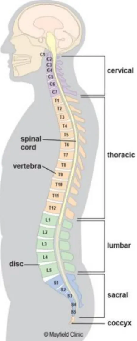
The spinal column is a musculo-skeletal system of the human body that connects the upper limbs to the lower body and protects the spinal cord. It is composed of alternating vertebrae and intervertebral discs (IVDs) supported by the robust ligaments and muscles. The asymptomatic spine is straight in the frontal plane, while it has two lordotic and two kyphotic curves in the sagittal plane with five particular segments including the cervical, thoracic, lumbar, sacrum, and coccyx regions (Figure 2-1). The cervical spine is composed of seven vertebrae (C1-C7) and has an arch convex anteriorly in the sagittal plane, known as cervical lordosis. This region of the spine supports the weight of the head and provides mobility. The thoracic spine encompasses twelve vertebrae (T1-T12) with an anteriorly concave curvature in the sagittal plane, denoted by thoracic kyphosis. The lumbar spine includes five vertebrae (L1-L5) and forming a lordosis. The lumbar spine forms the lumbosacral curve, which supports the body weight and maintains the spinal balance. The sacrum (S1-S5) and coccyx (Co1-Co4) are made of fused vertebrae and together form a kyphotic shape in the sagittal plane. The sacrum is a part of pelvis linking the lumbar spine to the lower limbs. The coccyx, or tailbone, is attached to the end of the sacrum and plays a role in the load bearing, especially in sitting.
Figure 2-1 Natural spinal curves and different regions of the spinal column (obtained from https://www.mayfieldclinic.com/PE-AnatSpine.htm on 2018-03-12)
2.1.1 Vertebrae
The vertebrae are the main building blocks of the spine and are connected by the spinal ligaments and intervertebral discs that form a coiled spring structure. This arrangement helps to bear the majority of the weight, to serve the mobility to the upper body as well as to protect the spinal cord. Each vertebra has two major parts: (1) the anterior vertebral body, and (2) the posterior part denoted as the neural arch. The vertebral body is the largest part of a vertebra; it has a drum shape that plays a significant role in bearing the loads and withstanding against the compression. In terms of morphology, the vertebral body is generally composed of porous trabecular bone surrounded by a
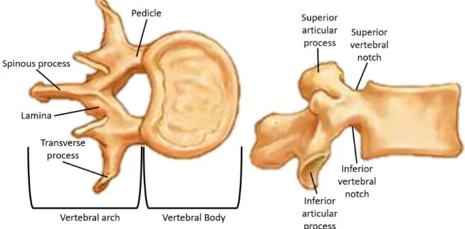
thin layer of cortical bone, which serves the load bearing ability. The neural arches are bony projections in the back of the vertebrae and are composed of two pedicles, two laminae, two transverse processes, one spinous process, and four facet joints. The vertebral body and neural arches form a central vertebral foramen, which creates a vertebral canal to protect the spinal cord. The superior and inferior notches of the adjacent pedicles construct the intervertebral foramina, through which the spinal nerves pass (Figure 2-2).
Figure 2-2 General structure of a typical lumbar vertebra. Each vertebra has generally two particular parts including the vertebral body and posterior arches. (Modified picture taken from http://craftbrewswag.info/lumbar-vertebrae/ on 2018-03-13)
2.1.2 Intervertebral discs
The intervertebral discs (IVDs) lie between two adjoining vertebrae and connect them together. They provide the load bearing and shock absorption ability while offering the mobility to the spine. The IVD has a fibrocartilaginous construct and is composed of two parts: the nucleus pulposus (NP) and annulus fibrosus (AF). The core of the intervertebral disc, i.e. NP, is a fluid-like jelly material embedded in composite-like material of AF (Figure 2-3-A).
A B
Figure 2-3 Structure of the intervertebral disc, A) NP and AF composed of concentric layers, B) Orientation of collagen fibers of the AF [19]
Water content in the adult healthy disc is approximately between 70% and 80% [20], but it can decrease due to disc degeneration, so called disc dehydration. The AF is a ground material filled with obliquely oriented collagen fibers at about 30°. Collagen fibers are arranged in 15-25 concentric sheets [19] known as lamellae. They are oriented in a reverse direction between two adjacent layers with an angle around 120° (Figure 2-3-B).
2.1.3 Ligaments
The spinal ligaments are connective tissues holding vertebrae together along the spinal column to stabilize the spine and protect the IVDs. There are seven major ligaments, including the anterior longitudinal ligament (ALL), posterior longitudinal ligament (PLL), capsular ligaments (CL), ligamentum flavum (LF), interspinous ligaments (ISL), supraspinous ligaments (SSL), and intertransverse ligaments (ITL). They run from the base of the skull to the sacrum and prevent the excessive flexion, extension, and rotation in each segment (Figure 2-4).
The ALLs are the thick ligaments passing the anterior part of the spine. These ligaments are attached to the adjacent endplates and IVDs, thus preventing the hyperextension of the spine, and avoiding the disc herniation. The PLLs are also lining the posterior side of the vertebral bodies inside the spinal canal to restrict against the posterior prolapse and disc protrusion. The CLs bind
the adjacent superior and inferior articular processes and enclose the articular facet joints. These ligaments have the major contribution to the resistant forces in flexion of the spine. The LFs connect each two adjacent laminae and are highly elastic compared to the other spinal ligaments. The key role of these ligaments is to assist straightening of the flexed spine, to restrict the separation of two adjacent laminae, and to protect the spinal cord. The ISLs are between two neighbouring spinous processes, while the SSLs link their rips. Together, SSLs and ISLs restrict the hyperflexion of the spine. The ITLs are discontinues, connecting two adjoining transverse processes, and contributing to the stability of the spine in lateral bending.
Figure 2-4 Seven spinal ligaments (Taken from: https://www.studyblue.com/notes/note/n/neck-trunk/deck/10491924 on 2018-03-13)
2.2 Biomechanics of the asymptomatic spine
2.2.1 Spinal loads
The spinal column is the main structure sustaining the loads in the musculoskeletal system while providing sufficient flexibility to the upper body [21]. The spinal loads are generated by the spinal muscles and soft tissues to counteract the exerted moments and loads to the spine as well as gravity [21, 22]. Physiological loads are generated in daily movements such as bending, sitting, standing, walking, running, and jumping, but the fast and dynamic movements produce significantly higher magnitude loads. In vivo measurements of the intradiscal pressure (between 0.98 to 1.47 MPa) in the sitting posture indicate the role of the IVDs as a load bearing component in the spine [23]. The transferred loads to the FSUs are indicators that could be used to assess the risk of spinal injury or failure, however, they cannot solely determine either the tissue damage or source of pain [22]. The spinal muscles, ligaments, and intra-abdominal pressure (IAP) collectively preserve the stability of the spine [22, 24]. Muscle forces, governed by the nervous system, not only stabilize the spine in upright standing, but also promote and control the movements [22]. In addition to the muscle forces, spinal ligaments and articular joints constrain the extreme movement of the spine. When the muscle and ligament forces increase, the intra-abdominal pressure rectifies the tension along the spine, which moderate the extra compression by generating a hydrostatic pressure on the pelvic and diaphragm [22, 25-27]. The intradiscal L3-L4 pressure measured as a function of posture showed that sitting vs. standing can increase the pressure about 2 times [23]. In lifting an object, the weight, size, lifting speed, and lifting technique would directly affect the spinal loads [24]. Intra-abdominal pressure and muscles contraction may compensate a portion of excessive loads generated by a poor lifting technique. In dynamic activities, the spinal loads are added by the inertial forces and are correlated to the speed and posture [24, 28].
Quantification of the spinal loads generated by the gravity and muscles forces is limited by the available measurements. Schultz et al. [29] proposed to simulate the body weight in numerical simulations by allocating 14% body weight to T1 with the segmental increment of 2.6% toward L5. In order to take the center of mass of the vertebra into account, Clin et al. [30 1880] adapted this load approximation technique and applied a shift to the point of action of each equivalent load in the sagittal plane. Applying a compressive vertical load to each motion segment for the purpose
of gravity force mimicking led to the buckling of the spine in a load magnitude even 10 times lower than the physiological loads [31]. Application of a “follower load” has been widely used in the biomechanical studies to minimize the effect of the shear forces at a motion segment. A follower load can be applied through the curvature of each motion segment in numerical studies, and might be integrated by using a wire-guide system in experimental studies [31].
2.2.2 Spinal Motion
Spinal motion is made by the interaction of spinal elements that allows one vertebra in a motion segment to rotate and translate with respect to the adjacent vertebra. The spinal load-deformation behavior of the motion segment can be characterized to evaluate its stiffness in different loading conditions. This curve has a non-linear behavior with apparently two distinguished regions (Figure 2-5). The first region, the neutral zone (NZ), has a relatively large deformation for a low applied force due to the laxity of the IVDs and spinal ligaments. The next stiffer zone, elastic zone (EZ), is beyond the neutral zone up to the maximum physiological limit. The range of motion (ROM) is the summation of these two regions that, indeed, is the movement of the spinal segment from neutral position up to the limit of motion [24, 32]. The neutral zone is an interesting indicator to assess the spine health, since injuries, degeneration, and surgical intervention could modify the ROM (Figure 2-6).
Figure 2-5 A typical load-deformation curve of a joint, e.g. between two adjacent vertebrae, has two major regions: the flexible region at low load called neutral zone (NZ); and stiff region called elastic zone (EZ). NZ and EZ together provide the range of motion (ROM) [33]
Figure 2-6 Segmental range of motion for each spinal segment in flexion-extension, side bending, and axial rotation summarized from [32]
The spinal movement has two substantial components: rotation around and translation along the anatomical axes (Figure 2-7). Forward and backward rotations around the sagittal axis (Y) are known as flexion and extension, respectively. Lateral bending and axial rotation refer to the rotation around the coronal (X) and transverse (Z) axes, respectively.
Figure 2-7 Each spinal segment provides six degrees of freedom (DOFs): three translations and three rotations (Image taken from [24])
0 5 10 15 20 25 30 35 40 C0 -C 1 C1 -C 2 C2 -C 3 C3 -C 4 C4 -C 5 C5 -C 6 C6 -C 7 C7 -T 1 T1 -T 2 T2 -T 3 T3 -T 4 T4 -T 5 T5 -T 6 T6 -T 7 T7 -T 8 T8 -T 9 T9 -T 10 T1 0-T 11 T1 1-T 12 T1 2-L 1 L1 -L 2 L2 -L 3 L3 -L 4 L4 -L 5 L5 -S 1
2.3 Spinal pathologies with the disc as the source of mechanical back
pain
Intervertebral disc degeneration (DDD for degenerative disc disease) is the change in the structure and function of the disc, and is initiated by aging or mechanical overloading [34]. Early age-related degeneration often starts off in the NP and reaches the AF [22]. Water content and proteoglycans concentration are respectively 88% and 65% of the dry weight of an asymptomatic disc, and respectively decrease to 65% and 16% with degenerative pathologies [35]. As the NP loses its water content or the AF becomes weak, the IVD collapses and places a pressure on the nerve roots. This situation may lead to the spinal instability and cause the back pain.
One of the most common disc diseases is disc herniation, a situation when gel-like material of the NP leaks out and induces a pressure on the nerve roots. Loss of the nucleus function causes an abnormal force to the AF and initiates the micro-tears in the AF, lamellae, or near the endplates [36]. Overloading the spine may yield the encased NP to escape the AF. This prolapsed material may place a pressure on the nerve roots and cause irritation. The disc degeneration may progress until the destruction of the soft tissues constraining the FSU [20]. Based on the radiological and morphological assessments, Thompson et al (1990) [37] proposed a classification of the disc degeneration from grade I to V. Grade I is corresponding to the healthy disc with rounded nucleus, while the intervertebral disc space collapses in grade V (Figure 2-8).
Figure 2-8 Classification of disc degeneration proposed by Benneker et al. (2005) [38]. From grade I (a) to grade Ⅴ (e), the severity increased based on the evaluation of radiological parameters such as disc height, nucleus roundness, and colors
2.4 Transforaminal lumbar interbody fusion (TLIF)
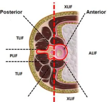
Spinal fusion is a surgical treatment to restore the disc height and segmental lordosis, as well as to increase the stability of the spine. The procedure includes removal of the NP and a portion of the AF, intervertebral disc, partial facetectomy, segment decompression, and insertion of an interbody cage into the intervertebral space. In addition to the cage insertion at the anterior column, a posterior instrumentation brings further solidity to the FSU. To achieve the surgical objective, several techniques are proposed (Figure 2-8):
• anterior lumbar interbody fusion (ALIF) considers an anterior abdominal approach to access to the intervertebral disc space;
• posterior lumbar interbody fusion (PLIF) to access to the disc space with a posterior incision;
• transforaminal lumbar interbody fusion (TLIF) is an unilateral approach to implant the interbody cage.
Figure 2-9 Common surgical fusion approaches (Image taken and modified from https://pbrainmd.wordpress.com/2015/10/11/lumbar-interbody-fusion/ on 2018-03-13)
2.4.1 Description of TLIF procedures
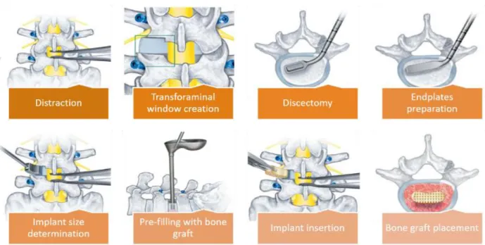
Transforaminal lumbar interbody fusion (TLIF) uses the unilateral mediolateral approach to access the intervertebral disc space [2]. The TLIF procedure is presented in the Figure 2-10 according to the standard practice reported in the literature [2, 3]. To access the disc space, the patient is placed in the prone position on a surgical frame. A vertical incision is made over the segment undergoing the fusion. Then, the surgeon retracts the muscles and soft tissues to reach the spinous process, the lamina, and the facet joint. Depending on the type of pathology and required decompression, laminectomy and/or facetectomy may be carried out.
After primary decompression of the nerve roots, pedicle screws are inserted according to the standard procedure. To reach the intervertebral disc space and perform discectomy, the segment may be distracted by using pedicle screws and distractor tools. Discectomy should be carefully performed by removal of the NP and inner layers of AF, while the outer layers of the latter are kept to retain the bone graft after cage placement. Next, the appropriate cage (size) is inserted between two endplates and the rest of intervertebral space is filled with bone graft. After anterior stabilization and restoration of the disc height, rods are placed, and pedicle screws become tighten to achieve the desired lordosis angle (Figure 2-11). Compared to the ALIF, TLIF requires less retroperitoneal dissection with lower risk to damage the large blood vessel going to the legs; TLIF also necessitates less perineural retraction than PLIF [2, 39, 40].
Different interbody cages are available for the TLIF surgical intervention. Cage variations include the material (auto-graft iliac crest, allograft bone, carbon fiber cages, titanium mesh cages, polyether ether ketone (PEEK), and n-HA/PA66), the geometry (footprint, height, and other dimensions), the general shape (bullet or banana- shape vs. straight cages), the morphology of the surfaces in contact with the endplates (flat vs. biconvex), and the cage angle (wedge vs. flat or parallel) (Figure 2-12).
Figure 2-10 The detailed procedure of TLIF
Figure 2-11 The lumbar spine underwent single level TLIF (Image taken from http://img.medicalexpo.com/images_me/photo-g/79814-4109787.jpg on 2018-03-13)
Figure 2-12 Interbody cages with different shapes and materials (Image taken from [41])
2.4.2 Biomechanics of TLIF
TLIF aims to restore the intervertebral disc height and lumbar lordosis, to maintain the achieved stability by the means of interbody cages in anterior column and posterior instrumentation. Mechanical strength of the implant, its durability under cycling loads (fatigue strength), and its capability to restore the sagittal balance are three key features to assess the performance of the spinal instrumentation [42]. Since each pathologic condition has its own nature, the appropriate implant and instrumentation technique are required to assure the proper stability of the spine. The complications associated with the pedicle screws for the spinal fusion when utilizing only posterior instrumentation are attributed to the lack of anterior column stability [43]. It was shown that the use of interbody cages and posterior instrumentation in TLIF resulted to effective outcomes and 19 patients out of 20 were able to go back to work [44].
Experimental cadaveric tests of the healthy spine demonstrated that the posterior elements only withstand 20% of the compressive loads and the rest (80%) passes through the vertebral body [45].
In vitro studies showed that the spinal loads in flexion-extension were transferred by almost the
same and opposite loads (about 165 N) in the anterior disc and posterior instruments; unlike, in lateral bending, the majority of loads were carried by equal and opposite loads in posterior instruments (about 140 N) [46]. Based on the Wolff’s law, a sufficient compression is required to stimulate the bone remodeling. Once the load balance between the anterior and posterior column is not properly restored, increased or decreased stress may result to osteophyte formation or bone resorption, respectively [47].
A posterior fixation is used to increase the stability of the fused segment by decreasing the mobility of the FSUs. It has been proven that the use of pedicle screw fixation greatly increases the rigidity of the spinal segment after fusion surgery. Using a solid posterior fixation allows to share the loads between the anterior and posterior columns. Semi-rigid fixation is a potential alternative [48] to share more loads with the anterior column in the range of physiological loads, and also promoting the solid fusion of the adjacent vertebrae. Cadaveric experimental tests and finite element analyses showed that the interbody cages augmented by posterior instrumentation reduced the ROM at the fused segment to lower than 1⁰ while it was between 2⁰ and 8⁰ for uninstrumented (intact) model [11, 15, 49, 50].
The sufficient strength of the screw anchoring is required to fulfill the efficacy of the posterior fixation against the imposed loads. Pedicle screws with outer diameter of 6.5 mm vs. 4.5 mm increased the pullout strength from 0.97±0.05 kN to 1.53±0.01 kN [51]. Osteoporosis causes the compromised bone quality and may drastically reduce the pullout strength from more than 1000 N to below 400 N [52]. Double threaded pedicle screws are proposed to increase the pullout strength of single threaded one; the pullout strength in cycling loading condition was 140±37.9 N for the former and was 121.8±41 N for the latter (p=0.44) [53].
2.4.3 Failure modes in TLIF
A fusion rate of 92.5% to 97% is reported by the clinical follow-up studies after TLIF [5, 8, 54-56]. Clinical studies reported failures of the TLIF procedure, which is attributed to cage subsidence, failure of the posterior instrumentation, and adjacent segment degeneration (ASD). Cage
subsidence is a situation that endplate cannot tolerate an excessive amount of load imposed by the interbody cage resulting in the endplate collapse and loss of the fusion failure [57] (Figure 2-13). Several risk factors of cage subsidence in TLIF have been identified, such as the cage geometry (shapes, sizes, etc.) [5, 7-12], single cage vs. paired cages [13] , and the use of unilateral posterior fixation vs. bilateral one [14, 15]. Placement of expandable cages increased the segmental lordosis from 3.54° before surgery to 6.37° by 24 months with insignificant subsidence and fusion rate of 92.5% [58]. Placement of an interbody cage with a greater height offers a better restoration of segmental lordosis but requires a higher distraction. Increasing distraction of the segment ascends the compression force in endplate-cage interface that may results to a higher risk of cage subsidence. Experimental tests using cadavers showed that this compressive force was 8.8 N with the insertion of a 6 mm height cage while it increased to 21.5 N with a cage of 8 mm height [16]. 16% more anterior placement of the interbody cages resulted to 2.11° more segmental lordosis restoration [17] and a lower risk of cage subsidence due to shifting the endplate-cage interface to the peripheral region of the endplates with superior mechanical strength. Osteoporosis increased the risk of cage subsidence up to 8 times higher [59], thus enough contact between the interbody cages and endplates should be maintained to uniformly distribute the loads and avoid the cage subsidence [11].
The stiffness of the posterior fixation mostly depends on the diameter of rods, their material, and their diameter. It is reported that 40% elongation of the diameter of the rods increased the bending moment and axial force on the fixator up to 82% and 33% [60]. The risk of rod failure is higher in smaller rods due to the greater deformation and consequently higher internal stresses; however, more rigid rods apply higher portion of the loads to the pedicle screws increasing the risk of pullout. Some other aspects of pedicle screw fixation in terms of pullout strength are described in Figure 2-13.
Figure 2-13 Measurement of the cage subsidence from the radiological evaluation (Image taken from [6])
Since TLIF restrains the mobility of the fused segment, the motion of the adjacent segments will increase to achieve the total required displacement resulting to the elevated intradiscal pressure in those FSUs [61, 62]. It is reported that the stresses in the intervertebral discs of the adjacent segments increased up to 10% when the lumbar spine underwent whether single or multi-level fusion, but the increment was higher in multi-level TLIF [62]. In addition to the stiffness of the fused segment, higher sagittal orientation of the facet joints at the adjacent segments surged the risk of symptomatic adjacent segment disease [61]. Nevertheless, the mechanical interventions are not the only risk factors of ASD. Physiological and environmental factors also contribute the initiation and progression of the disc degeneration.
2.5 FEM of the lumbar spine and TLIF
2.5.1 Finite element modeling of the spine
2.5.1.1 FEM of vertebrae
The geometrical parameters of the vertebrae such as their dimensions and morphology can be extracted from medical images. Two main approaches exist to develop a FEM of the spine: “generic” and “patient-specific”. The generic geometry modeling is based on anatomical measurements integrated in a parametrized approach [63]. In certain models, the geometry is assumed as symmetric in the sagittal plane (Figure 2-14. A). Personalized models can be obtained through medical images converted into different mesh elements [63-65] (Figure 2-14. B). Isotropic [66-69] or transversely isotropic [70, 71], or orthotropic [72] elastic and elasto-plastic materials can be used to simulate the mechanical behavior of the bony components.
A B
Figure 2-14 A) Generic model with parametrized body height, width, depth, and thickness [73], and B) a specimen FEM of the L3 lumbar vertebra
2.5.1.2 FEM of lumbosacral functional units or segments
The lumbosacral FEMs consist of lumbar vertebrae (L1 to L5), sacrum, IVDs, spinal ligaments, and pertinent joints. These models are used to study the spine biomechanics, better understand mechanisms of spinal injuries, and analyze the spinal instrumentation.
The IVD may be modeled as axisymmetric [74, 75] or symmetric [74, 76] volumetric elements. Some more realistic models consider the concave profiles of the caudal and cranial surfaces of the IVD in contact with the vertebral endplates [7, 14, 15, 77, 78]. 3D elements allow to simulate AF ground material and NP. Truss or bar elements in the 3D solid elements can represent the collagen fibers of the AF. The spinal ligaments may be included into the FEMs by using the cross-sectional area measured experimentally. The spinal ligaments may be modeled as 2-node truss, cable, or spring elements with linear or non-linear elastic or viscoelastic behaviour. The facet joints can be integrated in the model by using contact elements with initial gaps between 0.4 and 1.25 mm [67, 70, 77-79].
Incompressible hyperelastic Neo-Hookean or Mooney-Rivlin formulation can represent the mechanical behaviour of the NP and AF [66-71]. Linear or non-linear elastic or viscoelastic may mimic the mechanical behavior of collagen fibers. Linear elastic [71], piecewise non-linear [69], non-linear [66, 68, 70], or exponential [72] stress-strain curves may be used to represent the spinal ligaments behavior.
The volumetric (solid) elements in these models allow to accurately compute the stresses and strains in the spinal parts [80-82]. To shorten the processing time, when a detailed stress analysis is not necessary, vertebrae can be assumed as rigid bodies and other parts may be simulated as simplified elements [82]. The hybrid modeling (rigid and flexible elements) allows to calculate the stresses and strains in the target regions while the rest of components are simulated as rigid bodies [80, 82].
2.5.2 Critical review of lumbar spine finite element models
Several FEMs of the spine have been developed to study the stress distribution in different spinal components and to assess the posture of the lumbar spine under compression, lateral bending, and axial rotation. Shirazi-Adl [77] developed and validated a FEM of the L1-L5 lumbar spine based on CT images taken from cadaveric specimen and validated it by using the results of his previous experimental tests. Little et al. [69] developed a FEM to investigate the role of geometrical parameters of the spine on the coupled rotations. They used a 59-year old female cadaver to build the L1-L5 lumbar model and validated it against the in-vivo radiological measurements performed
by Pearcy [83]. In 2009, Zander et al. [68] developed a FEM of the L1-L5 lumbar spine based on CT measurements of cadavers and validated against the available experimental data. This model was used to evaluate the kinematics of the spinal motion segment with the use of a developed arthroplasty implant in flexion, extension, lateral bending, and axial rotation.Ayturk and Puttlitz [72] created a L1-L5 lumbar FEM on the basis of CT images of a 49-year old female, and validated it by using the ROM under a 7.5 Nm bending moment simulating flexion, extension, lateral bending, and axial rotation. Based on the CT scan of a cadaveric subject, Kiapour et al. [67] developed a FEM of the L3-S1 spine and validated it by comparing the ROM in physiological loading conditions with those experimentally measured on human cadavers. This model has been widely used to investigate different spinal fusion techniques as well as artificial disc replacement. To mimic muscle forces and upper limbs weight, a compressive 400 N follower load was applied before the segment underwent physiological loads [7]. In 2012, Schmidt et al. [70] built a FEM of the L1-L5 spine from CT-scan images of a 46-year old cadaveric subject and validated it against the experimental data of ROM. A 500 N preload was applied to simulate the upper body weight and local muscle loads, and then the biomechanics of the multilevel disc arthroplasty was assessed. A FEM of the L1-L5 spine was created by Li et al. [84] using the CT-scan images of a 19-year old healthy subject and was validated to assess the biomechanical performance of a new semi-flexible posterior fixation.
SM2S (Spine Model for Safety and Surgery) is a detailed and realistic model of the whole spine developed and validated within the iLab-Spine (partnership between the Laboratory of Applied Biomechanics of IFSTTAR/AMU, Polytechnique Montréal, École de technologie supérieure and other hospitals) [85]. The geometry is reconstructed on the basis of CT-scan images (0.6 mm slice thickness) of a 50th percentile healthy male, and includes all the vertebrae, pelvic, IVDs, spinal ligaments, and facet joints [78,79]. The cortical and trabecular bony parts are modeled by 4-node tetrahedral elements by considering the local variation of thickness of the cortical shell. The 8-node hexahedral elements represent the IVDs and 8 layers of collagen fibers (uniaxial springs) reinforce the AF. The spinal ligaments are modeled by the 4-node shell elements, except the CLs which were modeled by 3-node shell elements. Bony elements are governed by the homogenous elasto-plastic Johson-Cook law. The IVDs are assumed as the hyper-elastic Mooney-Rivlin formulation while the collagen fibers are governed by a non-linear load-displacement curve. The spinal ligaments
follow the generalized Maxwell-Kelvin-Voigt viscoelastic formulation. Facet joints are modeled by a frictionless contact interface.
These FEMs are associated with the inherent limitations, which are caused by the complex geometry of the spine, non-linear behavior of the tissues, complicated loading and boundary conditions, and variability of the reference specimens. The FEMs generally are validated against the available experimental data for the ROM in compression or pure moment, but intradiscal pressure and facet joint force might vary between the models [86], which weaken their robustness to predict different biomechanical measures of TLIF. Also, they are built based on the geometry of only a limited number of specimen, hence hindering the inter-variability between different spinal geometries. Not only the geometry, but material properties of the spinal elements change with different situation such as age, gender, and quality of life. Rarely, these FEMs were subjected to the combined loading condition which are more realistic and predictive. In brief, although these developed FEMs are capable to simulate some biomechanical aspects of the spine, a significant effort is still required to gain more realistic FEMs.
2.5.3 Critical review of previous biomechanical FEM studies of TLIF
Li et al. (2015) [84] developed a non-linear FEM of the L3-S1 to compare the biomechanics of pedicle screw-rod vs. plate as posterior fixation in TLIF. Also, this study investigated the difference of the unilateral vs. bilateral posterior fixation under a bending moment of 7.5 Nm following a 400 N follower load. The TLIF was done at the L4-L5 level, and the endplate-cage interface was modeled as a finite sliding contact with a friction coefficient of 0.2. The results demonstrated that both posterior instrumentations remarkably reduced the ROM to around 1°, and the plates had identical outcomes to the rods. Bilateral vs. unilateral posterior fixation was more effective to decrease the ROM (up to 74% with unilateral instrumentation and 88% with bilateral). The maximum Von-Mises stresses in caudal screws ranged from 0.9 to 2.2 times higher with the use of plates than rods.
Faizan et al. (2014) [7] used a previously validated FEM of the L3-S1 lumbar spine to assess the risk of cage subsidence in the TLIF as a function of cage footprint as well as to evaluate a new designed interbody cage under a combination of 10 Nm bending moment and 400 N follower load.
Unlike the other finite element models of TLIF that did not consider the distraction procedure, in this study, distraction procedure was modeled to assure an intimate endplate-cage contact (rough friction contact). The use of an interbody cage with 75% larger footprint (490 vs. 280 mm2), although increasing the sustained compressive load at the endplate-cage interface by about 300%, it reduced the maximum stresses up to 50% resulting in a lower risk of cage subsidence
Tang (2015) [87] modified an existing FEM of the L3-L5 to compare the biomechanics of TLIF and PLIF. The degrees of freedom of the L5 inferior surface were fixed, and the model was subjected to a combination of 800 N compressive load and 10 Nm bending moment in different anatomical planes. The endplate-cage interface was virtually considered as a solid fusion. The result showed that TLIF and PLIF increased the intradiscal pressure at the level above the fusion up to 78.3% and 104.3%, respectively. To compensate the lack of mobility at the fused segment, the ROM was increased by 19.2% at the level above with potentially increasing risk of ASD. Agrawal et al. (2013) [10] developed a L4-L5 FEM to relate the stress distribution at the endplate-cage interface to the conformity of a tissue-engineered polycaprolactone-hydroxyapatite (PCL-HA) interbody. The interface was modeled as a surface-to-surface finite contact with the friction coefficient of 0.3, and a 400 N follower load followed by a 7.5 Nm bending moment were applied to the FEM. Using the conformal vs. non-conformal interbody increased the contact area by 55% and 229% in flexion and extension, respectively. The increased contact area, subsequently, resulted to the reduced stresses at the endplate-cage interface by 33% and 38% in flexion and extension, respectively, thus a lower risk of cage subsidence is expected.
Lo et. al. (2011) [88] used a previously validated FEM of the L1-L5 lumbar spine and simulated TLIF at the L3-L4 motion segment with the use of two posterior instrumentation systems, namely Coflex-F and pedicle screw-rod. The endplate cage interface was modeled as a surface-to-surface contact with a friction coefficient of 0.8, which represents the fusion condition. The adapted FEM were subjected to a 400 N follower load followed by a 10 Nm bending moment representing physiological loadings in lateral bending and axial rotation. The Coflex-F vs. pedicle screw-rod posterior instrumentation increased the maximum stresses at the endplate-cage interface about 50%, 80%, and 50% in flexion, lateral bending, and axial rotation.
Chen et al. (2012) [15] adapted a L1-S1 lumbar FEM and simulated TLIF at the L4-L5 motion segment to evaluate the difference of unilateral and bilateral posterior fixation. A surface-to-surface
![Figure 2-3 Structure of the intervertebral disc, A) NP and AF composed of concentric layers, B) Orientation of collagen fibers of the AF [19]](https://thumb-eu.123doks.com/thumbv2/123doknet/2345472.34789/26.918.165.762.155.370/figure-structure-intervertebral-composed-concentric-layers-orientation-collagen.webp)
![Figure 2-6 Segmental range of motion for each spinal segment in flexion-extension, side bending, and axial rotation summarized from [32]](https://thumb-eu.123doks.com/thumbv2/123doknet/2345472.34789/30.918.185.733.134.398/figure-segmental-segment-flexion-extension-bending-rotation-summarized.webp)
![Figure 2-12 Interbody cages with different shapes and materials (Image taken from [41])](https://thumb-eu.123doks.com/thumbv2/123doknet/2345472.34789/36.918.205.714.111.585/figure-interbody-cages-different-shapes-materials-image-taken.webp)
![Figure 2-13 Measurement of the cage subsidence from the radiological evaluation (Image taken from [6])](https://thumb-eu.123doks.com/thumbv2/123doknet/2345472.34789/39.918.297.623.98.550/figure-measurement-cage-subsidence-radiological-evaluation-image-taken.webp)
![Figure 2-14 A) Generic model with parametrized body height, width, depth, and thickness [73], and B) a specimen FEM of the L3 lumbar vertebra](https://thumb-eu.123doks.com/thumbv2/123doknet/2345472.34789/40.918.148.774.561.782/figure-generic-parametrized-height-thickness-specimen-lumbar-vertebra.webp)