ANAL YSIS AND DESIGN OF A NEW INTEGRATED MOBILE SIP PROXY
TO ENHANCE THE SCALABILITY IN MOBILE NETWORK OPERA TORS
THÉ SE PRÉSENTÉ
COMME EXIGENCE PARTIELLE DE LA MAÎTRISE EN INGÉNIERIE
Par
LINA ABOU HAIBEH
Jury d'évaluation
Examinateur Externe: Prof. Gilles Y. De lisle, Université Laval
Examinateur Interne: Prof. Nahi Kandi!, Université du Québec en Abitibi-Témiscamingue Directeur de Recherche: Prof. Nadir Hakem, Université du Québec en Abitibi-Témiscamingue
Mise en garde
La bibliothèque du Cégep de l’Témiscamingue et de l’Université du Québec en Abitibi-Témiscamingue a obtenu l’autorisation de l’auteur de ce document afin de diffuser, dans un but non lucratif, une copie de son œuvre dans Depositum, site d’archives numériques, gratuit et accessible à tous.
L’auteur conserve néanmoins ses droits de propriété intellectuelle, dont son droit d’auteur, sur cette œuvre. Il est donc interdit de reproduire ou de publier en totalité ou en partie ce document sans l’autorisation de l’auteur.
Warning
The library of the Cégep de l’Témiscamingue and the Université du Québec en Abitibi-Témiscamingue obtained the permission of the author to use a copy of this document for non-profit purposes in order to put it in the open archives Depositum, which is free and accessible to all.
The author retains ownership of the copyright on this document. Neither the whole document, nor substantial extracts from it, may be printed or otherwise reproduced without the author's permission.
ANAL YSIS AND DESIGN OF A NEW INTEGRATED MOBILE SIP PROXY
TO ENHANCE THE SCALABILITY IN MOBILE NETWORK OPERA TORS
A THESIS PRESENTED TO THE UNIVERSITE DU QUEBEC EN ABITIBI-TEMISCAMINGUE IN FULFILLMENT OF THE THESIS REQUIREMENT FOR THE
DEGREE OF MAS TER IN SCIENCE AND INFORMATION TECHNOLOGY
BY
LINA ABOU HAIBEH
COMMITTE MEMBERS
External Examiner: Prof. Gilles Y. De lisle, Université Laval
Internai Examiner: Prof. Nahi Kandi!, Université du Québec en Abitibi-Témiscamingue Research Supervisor: Prof. Nadir Hakem, Université du Québec en Abitibi-Témiscamingue
©Lina Abou Haibeh, 2018
ABSTRACT
The emergence of the two new technologies, namely Software Defined Network (SDN) and Network Function Virtualization (NFV) have radically changed the development of computer network fun etions and the evolution of mobile network operators (MN Os) infrastructures. The se two technologies bring to MN Os the promises of reducing costs, enhancing network flexibility and scalability to handle the growth in the number of mobile users and the need to extend its coverage to rural areas.
The aim of this thesis 1s to exploit the advantages of the NFV concept to support the implementation of full y integrated solution with an external Session Initial Protocol (SIP) proxy application to enhance the scalability in MN Os. The proposed solution offers a hosted SIP proxy application installed on a virtual machine (VM) environment. The SIP proxy provides full Private Branch Exchange (PBX) and Switch (SW) functionality with Interactive Voice Response
(IVR) capabilities. It maximizes the capacity in the existing servers and value-added services
(VAS) data centers within the MNOs. The proposed solution enhances the usage of the existing bandwidth by using the unlicensed radio frequency (RF) spectrum bandwidth instead of the licensed RF spectrum to support a larger number of smartphones and data plans.
In the initial experimental testbed, TeleFinity IP PBX, which is an external SIP proxy, 1s deployed on a virtual platform and integrated with the mobile network. The integration 1s realized by establishing a point to point protocol (PPP) SIP trunk connection between TeleFinity IP PBX and the Gateway Mobile Switch Center (GMSC). Severa! testing scenarios were carried out over a local area network (LAN) and a wide area network (W AN) using different voice codees: G.711 u-law, G. 723, and G. 729 to validate the voice cali quality offered by the proposed
solution. The Network analyzer software solutions: 1) Startrinity SIP tester, 2) Commview and
3) Resource Monitor are used to measure severa! Quality of Service (QoS) metrics. These include voice jitter, delay, packet Joss, and MOS. This procedure ensures that the proposed solution can handle voice communications with acceptable quality compared to LTE standards.
Keywords: Network Function Virtualization (NFV); SIP Proxy; Quality of Service (QoS); Scalability; Mobile Network Operators; Virtual machine
ACKNOWLEDGEMENTS
Working towards my master's degree has been a deeply enriching experience; at times it's been elating, but it has always been very rewarding. Looking back, many people have helped me to shape this journey. I would like to extend them my thanks.
I would like to express our deepest gratitude to my ad vis or, Prof. Nadir Hakem, for his invaluable guidance, encouragement, faith and advice during this research work. I would also like to thank my husband, Ousama Abu Safia, for his continuons support and kindness help. I have greatly benefited from observing how he dissects research problems.
I would also like to greatly appreciate and thank my family members and friends for their supporting and encouragement throughout my master's study.
LIST OF FIGURES ... ix
LIST OF TABLES ... xii
1 CHAPTER I INTRODUCTION ... .
1
1.1 Background ... .
1
1.2 Literature Review ... .4
1.3 Research Objectives ... 9
1.4 Research Methodology ... .
1 0
1. 5 The sis Structure ...11
2 CHAPTER 2 NETWORK FUNCTION VIRTUALIZATION ... 13
2.1 NFV Overview ... 13
2.2 NFV Key Benefits for MNOs ... 14
2.3 NFV and Software Defined Networking (SDN) relation ... 15
2.4 NFV architectures and key modules ... 18
2.5 NFV Design Considerations ... 22
2.6 V endor Specifie NFV Implementations ... 23
3 CHAPTER 3 VIRTUAL MOBILE SIP PROXY INTEGRATION ...
25
3.1 Virtual Network Functions Concept in MN0 ...
25
3.2 What is SIP Proxy ... 26
3.3 TeleFinity IP PBX Overview ... 26
3.3.1 TeleFinity IP PBX Benefits ... 28
3.4 TeleFinity IP PBX Modules ... 28
3.4.1 Call Center Module ... 29
3.4.2 Video Conference Module ...
30
Vl3.4.3 Interactive Voice Response (IVR) Module ... 31
3.4.4 Cali Recording Module ... 32
3.4.5 Cali Accounting Module ... 32
3.4.6 Fax Module ... 33
3.5 Mobile SIP Proxy Integration Approach ... 34
3.6 Proposed Architecture ... 37
3.6.1 Solution Design ... 37
3.6.2 VM Specifications ... 39
3.7 Signaling Stream Scenarios ... .40
3.7.1 UserRegistration Scenario ... .41
3.7.2 Mobile Cali Originating Scenario ... .42
3.7.3 Mobile Cali Terminating Scenario ... .45
4 CHAPTER 4 EXPERIMENTAL TESTBED IMPLEMENTA TI ON ... .48
4.1 Introduction ... .48
4.2 Experimental Testbed Setup ... .48
4.2.1 Hardware Parts ... .49
4.2.2 Software Solutions ... .49
4.3 Experimental Testbed Configuration ... 51
4.3.1 TeleFinity IP PBX Configuration ... 51
4.3.2 AcFinity IVR Configuration ... 52
4.3.3 Startrinity SIP Tester Configuration ... 54
4.4 Network Topology ... 54
5 CHAPTER 5 RESUL TS AND DISCUSSION ... 5?
5.1 Voice Codees Properties ... 57
5.1.1 G.711 u-law ... 5?
5.1.2 G.729 ... 58
5.2.2 Signaling Performance Parameters ... 62
5.2.3 Network Utilization Parameters ... 63
5.2.4 Hardware Utilization Parameters ... 64
5.3 Testing Scenarios and Results Analysis ...
65
5.3.1 Scenario 1: W AN Topo! ogy- RTP Passing Through SIP Proxy ...
65
5.3.2 Scenario 2: W AN Topo! ogy- RTP Not Passing Through SIP Proxy ... 73
5.3.3 Scenario 3: LAN Topology- RTP Passing Through SIP Proxy ... 80
5.3.4 Scenario 4: LAN Topology- RTP Not Passing Through SIP Proxy ... 86
6 CHAPTER 6 CONCLUSION AND FUTURE WORK ... 92
6.1 Conclusion ... 92
6.2 Future Work ... 94
7 REFERENCES ...
95
8 APPENDIX A ... 1 01
LIST OF FIGURES
Figure 1.1 LTE Network Entities [2] ... 2
Figure 2.1 Traditional network layers versus logicallayers in a SDN Network [30] ... 16
Figure 2.2 Indicative SDN architecture and mapping to NFV [30] ... 17
Figure 2.3 High Level NFV Domains [32] ... 18
Figure 2.4 End to end service Graph representation [32] ... 19
Figure 2.5 Architectural description ofNFV [32] ... 20
Figure 3.1 TeleFinity IP PBX Architecture© ... 27
Figure 3.2 Call Center Module Architecture© ... 29
Figure 3.3 Supported MultiMedia Services © ... 30
Figure 3.4 IVR Module Call Flow Designer [36] ... 31
Figure 3.5 Call Recording Module [34] ... 32
Figure 3.6 Call Accounting Module [34] ... 33
Figure 3.7 Fax Module© ... 34
Figure 3.8 Proposed Solution Diagram © ... 36
Figure 3.9 Proposed Solution Architectural Design© ... 37
Figure 3.10 User Registration Scenario© ... 42
Figure 3.11 Mobile Call Originating Scenario© ... 44
Figure 4.2 IVR System Settings © ... 53
Figure 4.3 Startrinity Configuration© ... 54
Figure 4.4 LAN Topology © ... 55
Figure 4.5 W AN Topology © ... 56
Figure 5.1 SRD Time [36] ... 62
Figure 5.2 SIP Proxy Services CPU Load © ... 64
Figure 5.3 SIP Proxy Services Memory Utilization © ... 65
Figure 5.4 W AN Topology- RTP Passing through SIP Proxy Scenario© ... 66
Figure 5.5 Scenario 1- Voice QoS Results ... 69
Figure 5.6 Scenario!. SIP Performance Results ... 70
Figure 5.7 Scenario 1- Network Utilization Results ... 71
Figure 5.8 Scenariol- Hardware Utilization Results ... 72
Figure 5.9 W AN Topology- RTP without Passing through SIP Proxy Scenario© ... 73
Figure 5.10. Scenario 2- Voice QoS Results ... 76
Figure 5.11. Scenario 2- Signaling Performance Results ... 77
Figure 5.12. Scenario 2- Network Utilization Results ... 78
Figure 5.13. Scenario 2- Hardware Utilization Results ... 79
Figure 5.14. LAN Topology- RTP Passing through SIP Proxy Scenario© ... 80
Figure 5.15. Scenario3- Voice QoS Results ... 82
Figure 5.16. Scenario3- Signa1ing Performance Results ... 84
Figure 5.17. Scenario 3- Network Uti1ization Results ... 85
Figure 5.18. Scenario3- Hardware Uti1ization Results ... 86
Figure 5.19. LAN Topo1ogy- RTP Not Passing through SIP Proxy Scenario© ... 87
Figure 5.20. Scenario4- Voice QoS Results ... 88
Figure 5.21. Scenario 4- Signa1ing Performance Results ... 89
Figure 5.22. Scenario 4- Network Uti1ization Results ... 90
Figure 5.23. Scenario4- Hardware Uti1ization Results ... 91
Table 2.2 Industry NFV projects ... 24
Table 3.1 Minimum VMs Specifications ... 39
Table 4.1 VMs Specifications used in the test bed ... 49
Table 4.2 SIP Extension Configuration Parameters ... 51
Table 4.3 SIP Trunk Configuration Parameters ... 52
Table 4.4 IVR Configuration Parameters ... 53
Table 4.5 Comparison between LAN and W AN ... 55
Table 5.1 VoiP Codees specification ... 59
Table 5.2 ITU-T Recommendation G.ll4 for Delay Specification [ 44] ... 60
Table 5.3 MOS Rating [46] ... 61
CHAPTERI
INTRODUCTION
1.1 Background
Recently, we have witnessed an explosion in the number of mobile phone users which accompanies to the appearance and emergence of new types of applications and services. As a result, an exponential increase in the data traffic has been addressed. This enormous data traffic leads mobile network operators (MN Os) to upgrade the ir systems, invest in their existing infrastructure, or look for new technologies and
solutions that help to satisfy the ir customers' demands. It is expected that these
demands will be fulfilled in the next generation of mobile networks; the so-called fifth generation (SG) network, which will achieve an extremely high data rate, ultra-low latency, high user mobility and ultra-reliable communication [1]. Moreover, it is expected that MNOs will be able to manage easily the huge number of mobile terminais and extend their coverage to rural areas without any additional cost.
MNOs have been evolved through four generations. Starting from being a circuit-based analog telephony system in the first generation (lG). Then, it became a partially based system in 2G and 3G, and finally, it became all-IP packet-based system in 4G/LTE. The 3GPP (3rd Generation Partnership Project) introduced a new mobile core network architecture called Evolved Packet Core (EPC) in LTE. This architecture is able to interoperate with the legacy of 2G and 3G systems [2]. The introduction of EPC (Evolved Packet Core) allows mobile users to access multimedia
resources in external packet data networks such as the futernet. On the other hand, the
current LTE mobile network architecture has severa! limitations that impose
challenges to MNOs toward upgrading their infrastructures. These limitations are
explained in details in the following points:
1) The LTE network entities, shown in Figure 1.1, include: 1) Mobility
Management Entity (MME), 2) Serving Gateway (SGW), 3) Packet Data
Network Gateway (PGW), 4) Home Subscriber Server (HSS) and 5) Policy
control and Charging Rule Functions (PCRF). These components are typically
based on a customized standard hardware which is usually configured,
deployed and provisioned in a static and cost-ineffective manner. This leads to
excessive capital expenditure (CAPEX) and operational expenditure (OPEX)
losses, besides an increased complexity in the management of the hardware
platforms.
•
User Equipment (UE) 5 1 - U U s er E quipmen1: (UE) Datil Pla nv Contrai Plane3
2) The control plane, which is responsible for the signaling between the EPC and the user for the users in the mobile network equipment (UE), and the data plane, which is assigned for the actual voice and data communication architecture, are tightly coupled at SGW and PGW. This coupled design results the inflexibility of network management, and limits the scalability of the network. Since the control plane and data plane have different performance requirements, the control plane requires low latency to process signaling messages, whereas the data plane requires high throughput to process the us ers' data traffic, it is necessary to decouple these planes to get them scaled independently and efficiently during the provisioning process. 3) The data plane of the current mobile architecture is centralized. Indeed, ali
uplink traffic from user equipment's (UEs) has always to traverse along a path that begins from the radio access, passing through the mobile backbaul, and then enters the IP networks via a small number of centralized PGWs. Even if sorne UEs are just communicating with local Application Services. Such a hierarchical architecture results an inefficiency in the data packet forwarding and the mobility management, in addition to a high latency. Thus, it is not suitable to fit the aforementioned SG requirements.
Recently, the advent of sorne cutting-edge technologies such as cloud computing, mobile edge computing, network virtualization, Software Defined Networking (SDN) [3], and Network Function Virtualization (NFV) [4] have changed the way network functions and deviees are implemented. Also, they changed the construction of network architectures. More specifically, the network's equipment or deviee is now changing from closed, vendor specifie to open and generic with SDN and NFV technologies. This enables the separation of control and data planes, and allows networks to be prograrnmed by using open interfaces.
With NFV, network functions which previously realized in costly hardware platforms are now implemented as software appliances placed on low-cost commodity hardware or running in the cloud computing environment. NFV technology together with cloud computing and network virtualization, bring to MN Os the promises of reducing the Capital Expense (CAPEX) [5] and the Operation Expense (OPEX) [6].It is also shortening the end-to-end network latency, enhancing network flexibility and scalability.
By taking the advantage of NFV implementation in MN Os, this thesis proposes an original software-based solution that allows having a scalable mobile network operator. The new architecture includes the integration with an external SIP proxy, and it is deployed on a virtual machine (VM). The VM can be defined as an emulation for computer system and provides the punctuality of physical computer. Moreover, the SIP proxy controls the cali management function in MN Os for newly added mobile users. More details will be discussed later in the thesis.
1.2 Literature Review
The challenges and limitations of mobile network architecture reqmre that many operators are being compelled to resort to iterative schemes of network planning. These include adding new infrastructure and backhaul to accommodate the growing demand for capacity and coverage. However, limited spectrum availability and the physical characteristics of radio waves do not allow a complete overhaul of the system beyond their capacity limits. MNOs, which are already CAPEX and OPEX constrained, are seeking for affordable, easily deployable, scalable and agile alternatives for network expansion. Many researches have been conducted to provide
5
smart mobile network expansiOn approaches that can resolve the aforementioned MNOs' limitations and challenges. Sorne ofthese approaches are discussed below:
Basta et al. in [7] proposed an architecture of virtualized mobile packet core (MPC)
gateways and NFV -based transport network elements. The control plane was not described in that work. The data plane entities are virtualized running on a data center platform. They are managed by a data center orchestrator. The NFV -based transport network is used to interconnect these virtualized gateways to the radio access and external IP networks. As a main contribution, the authors proposed severa! solutions to find the optimal data center location to host these virtual gateways so that the network Joad is minimized under a time-varying traffic pattern and a given data plane delay budget.
In [8], the same authors improved their work in [7] by addressing the function placement problem. They grouped the four deployment models in [7] into two main categories: a virtualized gateway (NFV) and a decomposed gateway (SDN). The first category refers to fully virtualizing SGW and PGW into a data center, and an off-the-shelf network element (NE) is used to direct the data traffic from the transport network to the data center. The second category refers to decomposing gateway functions, meaning that only the control plane function is shifted to the data center and integrated with SDN controllers while the data plane is processed by enhanced SDN network elements. To find the most optimal deployment solution, the authors in [8] formed a mode! by taking the control-plane Joad and data-plane latency into account, and then, tried to minimize these pararneters. By doing so, the operators will have a tool to make their own deployment decision: virtualizing ali gateways or decomposing ali gateways or a combination of the two.
The authors in [10][11] similarly adopted SDN and NFV into EPC S/PGWs. In these
articles, the control function of an S/P integrated gateway (S/PGW) is decoupled from the user plane. While virtualized S/PGW control is realized as VMs in a cloud
computing system. The S/PGW user plane can be realized either by VM or dedicated hardware. The dedicated hardware is usually located close to the access network and it is responsible for fast path processing.
SoftEPC in [12][13] presented a virtual network of EPC functions over a physical transport network topology. SoftEPC followed the concept of NFV by decoupling the network services and functions from the special purpose hardware. SoftEPC is composed of a collection of General Purpose Nodes (GPN) that are core-class commodity servers running hypervisor [12][13]. Hypervisor is a virtualization software that creates multiple virtual environments based on the physical hardware. The SoftEPC method can lead towards achieving significant saving in network bandwidth and processing Joad, especially in the core, by load-aware dynamic instantiation of P/S-GW functions on the GPN nodes. The SoftEPC shows the flexibility and elasticity compared with the conventional EPC. However, the authors
did not discuss in detail how the GPNs are managed. Taleb et al. in [13][13]
envisioned an end-to-end carrier cloud architecture . Ali the related EPC entities are virtualized as VMs running in a distributed manner at different data center (DC) locations. The VMs and their locations are launched on a carrier cloud service platform based on requirements of the number of the served subscribers at each
location [13][13]. In order to achieve an optimal end-to-end connectivity for UEs, the
Follow-Me-Cloud (FMC) concept is introduced. The main idea of FMC is to allow contents and services to follow the user during his/her movement. Thus, enabling the service continuity and reducing the end-to-end network latency. However, the shortcoming of this work is the Jack of how it works in reality. In addition, the detailed design of each functional unit and the interfaces used to communicate between them are not provided.
Similarly, the concept of having distributed data centers (DCs) to accommodate EPC functions is also introduced in Klein [13][15]. Klein is disruptive design for an elastic
7
cellular core by combining network functions virtualization with smart resource management. . Compared to [13][13] ,Klein also enables the placement of the data plane entities in a distributed manner. In addition, an orchestrator is introduced to allocate the network resources and to assign UE's data and network traffic to correct locations. By using a data driven analysis, the authors proved that Klein can almost optimally achieve the benefits of "clean-slate" approaches such as SoftCell [13][16] and SoftMoW [13][17] while working within the operational constraints of existing 3GPP standards. As an attempt to cope with the increase of Machine-to- Machine (M2M) or Machine Type Communications (MTC), the authors in [13][18] proposed a multi-vEPC architecture, which is able to provide optimized mobile communication service according to various requirements of M2M services. M2M services enable networked deviees to exchange information and perform actions without the manual assistance of humans. The M2M services are classified based on their requirements such as policy-based service, mobility required service or IP reachability required service. However, the authors did not describe in details the design of the EPC selector, how it works and how they classify the M2M services into different groups and in a static or a dynamic manner.
Another NFV-based EPC is presented m [13][19]. In this paper, the authors introduced the concept of EPC as a service (EPCaaS) each EPC entity is virtualized as an individual VM communicating to each other using 3GPP standard interfaces. As a practical realization of EPCaaS, Jain et al. [13][20] developed an open source software, which implements most ofthe conventional EPC functions and run them as VMs in a cloud system. Although these are the simplest ways o virtualiz EPC, Hawilo et al. [13][21] argued that such design can significantly impact the performance, for example, result in a longer communication delay between EPC VNFs. In order to solve that problem, the authors in [ 13 ][21] have grouped sever al VNFs together on the basis of their interaction and workload and intemalize communication between these VNFs, thus reducing the network latency.
While ali presented works assume the use of VMs to implement EPC VNFs without
considering the performance aspect(S), Kiess et al. [13] [22]provided a comparison of
different implementation models of PGW ( also applicable to other VNFs) such as deviee mode!, cloud-aware mode!, and software-as-a-service mode!. Through a cost-based evaluation, they find that the two last models have cost advantages in terms of OPEX saving.
Another approaches adopted the NFV concept in external networks such as IP Multimedia Subsystem (IMS) and internet to provide improve the services provided for mobile us ers. In [23],applying NFV concept for IMS system was introduced. The network functions of the IMS system was deployed in VMs, which have scalable hardware resources and can be dynamically relocated in cases of a VM's overload or failure [24]. Thus, the operator desired service continuity and service availability can
be obtained. Similarly, Lu et al. [25] proposed a cloud-based IMS architecture. The
architecture contains a Joad balancing algorithm and a mechanism for dynamic
resource allocation [24].Ito et al. [24][26] proposed a new EPC/IMS system based
NFV concept where each service can be processed by a particular virtual network to reduce the signaling Joad.
The aforementioned papers presented sorne of up-to-date solutions that adopted NFV into the core network in LTE and external networks such as IMS. However, there are still a number of issues need to be addressed in order to make these solutions feasible solutions and can be deployed in MN Os. Sorne open challenges raised in this domain such as the backward compatibility issue. The goal of the aforementioned issue is to find a flexible, effective and compatible design strategy with the existing mobile networks. Another challenge is related to the deployment mode! issue, which is concerns about finding a trade-off among varions deployment models based on careful evaluations.
9
In this thesis, the advantage of the NFV concept is utilized to develop a novel solution having a simpler integration architecture, lower cost and better customizability features compared to standard solutions. The proposed solution relays on the integration between external SIP proxy and the Gateway Mobile Switch Center (GMSC) without changing the current mobile network architecture. The new solution can be integrated with existing mobile network systems (2G, 3G, 4G and SG) systems. The SIP proxy is virtualized on VM and is responsible for the cali management functionality of the new added mobile users. Moreover, the performance and quality of SIP calls carried over a proposed solution are analyzed in this thesis. The testing carnpaigns are carried out in a real environment for different voice codees, G.711, G.727 and G.723.1.
1.3 Research Objectives
The primary research objective of this thesis aims to integrate the Session Initiation Protocol (SIP) proxy with the mobile operator network to resolve the aforementioned scalability related limitation.
The proposed solution allows achieving the following objectives:
1- Maximizing the use of existing bandwidth in order to to support more smartphones and data plans. Each virtualized SIP proxy is able to handle 2,000 concurrent calls and 12,000 users depending on virtual machine specifications;
2- Eliminate the need to install new proprietary hardware appliances. This would reserve more space and power resources in MN Os when there is a demand to increase the bandwidth;
3- Extend the coverage of MNOs in rural areas with minimum operation cost using the unlicensed RF spectrum;
4- Ensuring high levels of quality of service for ali subscribers wherever they are located;
5- Managing large traffic volumes securely across multiple data centers;
6- Utilizing the Network Function Virtualization (NFV) concept to enhance the functionality of the proposed solution;
7- Proposing an original solution that can integrate with any telephony system generations (2G, 3G, 4G and SG).
1.4 Research Methodology
The methodology steps related to this research project are introduced in the following points.
1- Implementing the proposed solution experimental testbed. It is divided into the following two parts:
a) Hardware Parts which include powerful servers to install virtual machines needed to implement a SIP proxy called TeleFinity IP PBX, IVR solution narned ActFinity IVR and Voicemail and SIP tester to generate SIP calls.
b) Software Solutions which include: 1) a TeleFinity IP PBX that serves as external SIP proxy to handle clients SIP calls, 2) Startrinity SIP cali generator, ActFinity IVR to receive the generated calls from SIP tester and play music file,
Il
3) Network analyzer software solutions such as real-time reports in Startrinity SIP tester, 4) Commview and Resource Monitor which is used to measure severa! Quality of Service (QoS) metrics such as voice jitter, end-to-end delay, packet Joss, and MOS.
2- Integrating the mobile network and the TeleFinity IP PBX by configuring the SIP trunk between them. N ext, installing the SIP client applications on the mobile deviees. Then, creating SIP extensions on the SIP Proxy application. Next, selecting the type of voice codee from the main system settings of TeleFinity IP PBX. The Voice Codees, G. 711, G. 729 and G. 723.1, will be selected for the tests.
3- Testing the calls' quality provided by the proposed solution. The calls' quality will be evaluated using four QoS metrics: mean opinion score (MOS), jitter, delay, and packet Joss to ensure that the proposed solution can handle voice communications with comparable quality to LTE standards.
1. 5 The sis Structure
This thesis is composed of six chapters including the first introduction chapter. Chapter II presents a general overview on NFV and its infrastructure. As weil, the roots ofNFV, key benefits and relation with Software Defined Networks (SDN) is the focus area in Chapter 2. Also, key benefits to telecommunication service operators through NFV are described briefly .Chapter 3 provides a detailed description for the proposed solution architecture, TeleFinity IP PBX modules and its main features. Signaling messages that are exchanged between MNO network components to handle any update in the registered subscribers information and status are discussed in Chapter 3. Chapter 4 describes the hardware specifications and software solution used
to implement the experimental testbed and evaluate the performance SIP proxy under virtualization environment for different voice codees, G.711, G.727 and G.723.1. Moreover, the SIP proxy configuration and the evaluation metrics are introduced. The solution network topology implemented over these two networks is described. Testing scenarios that carried on LAN and W AN network topologies are described in chapter 5. Parameters description which are measured during testing are also introduced. The testing results for the three voice codees G.711, G729 and G.723.1 are presented followed by analyzing the performance of the SIP proxy under a virtualization environment. Finally, the thesis 's conclusion in addition to the future work are presented in Chapter 6.
13
CHAPTER2
NETWORK FUNCTION VIRTUALIZATION
2.1 NFV Overview
NFV concept was introduced in 2012, when a number of leading Telecommunication Service Providers around the world introduced a white paper [27] calling for industrial and research activity. In November 2012, seven ofthese operators (AT&T, BT, Deutsche Telekom, Orange, Telecom Italia, Telefonica and Verizon) selected the European Telecommunications Standards Institute (ETSI) [28] to be the home of the Industry Specification Group for NFV (ETSI ISG NFV). Now, a vast community of experts are working deeply to develop the required standards for NFV as well as sharing their experiences of its development and earl y implementation.
The ETSI has proposed a number of use cases for NFV [29] such as Customer Premises Equipment (CPE), Virtual Evolved Packet Core (V-EPC), Open-BTS and Open- MSC.
As the NFV concept becomes mature, it is important to note that it is not only sufficient to deploy specifie network functions over virtualized infrastructures. Network users are generally not concerned with the complexity of the underlying network. All users require seamless network service to allow them access to the multi-media applications they need, anytime and anywhere. Therefore, NFV will only
be an acceptable solution for telecommunication providers if it meets the following key considerations: 1) Acceptable Network Architecture and Performance, 2) Security and Resilience, 3) Support for Heterogeneity, 4) Reliability and Availability, 5) Legacy Support, and 6) Network Scalability and Automation.
2.2 NFV Key Benefits for MN Os
NFV solutions can bring to telecommunication service operators many benefits. One of the most important benefits is the flexibility to evolve and deploy new network services within MNO platform in a more cost-effective manner. The aspects of the flexibility feature are presented in the following key points [30]:
• Hardware and software decoupling: The NFV eliminates the need for the
combination of the hardware and software network modules to develop specifie network service. Therefore, a separate planning and maintenance activities needed to be done.
• Flexibility in the network functions operations and design: The software and
hardware decoupling leads to the redesign of hardware resources and elements and their usage for multiple concurrent network operations. Due to this, operators can deploy network services faster for their clients running on the same hardware entities.
• Effective network scaling: The dynarnic scaling capabilities that are provided
with NFV enable the usage of NFV instances with different granularity. For instance, NFV solves the heavy traffic issue that is faced from the operators by deploying specifie NFV instance based on the traffic application scenario used.
15
It is worth remarking that the decoupling between software and hardware does not
mean that the resource virtualization of ali network elements is obligatory. Operators can still develop software and run it on the existing physical servers. The difference is that when running the software on virtual machines, this will result better performance and CAPEX/OPEX profits. Finally, hybrid scenarios where functions running on the virtualized resources can mutually operate and coexist with functions running on standard physical resources are suggested, till a full transition to virtualization takes place.
2.3 NFV and Software Defined Networking (SDN) relation
NFV is tightly coupled with SDN (Software Defined Networks). SDN is a networking approach which leads to the independence between controlling network functions and data forwarding functionality. For exarnple, right now a packet that arrives in a standard network element such as a router or switch must follow a set of forwarding or routing rules related to error correction, NAT (network address translation), QoS (Quality of Service) as weil as standard routing protocols rules [30]. SDN and NFV have started being developed independently, however it can be said that the former acts as complementary to the latter.
With the use of SDN, the above-mentioned operations of data forwarding, routing and network control functions are decoupled. To put it in a simpler way, data plane and control plane are decoupled, leading to centralized management of control plane and de-centralized data plane management [31].
SDN focuses on Layer 2 and 3 network elements and operations. SDN requires re-policing or re-configurations in the network infrastructure. As shown in figure 2.1, SDN decouples the network control and forwarding functions. This allows network control to become directly programmable via an open interface such as OpenFlow. As
weil, the Wlderlying infrastructure becomes simple packet f01warding deviees (the
data plane) that can be programmed
Error! Reference source not found.[30].
Figure 2.1 Traditional network layers versus logicallayers in a SDNNetwork [30]
The key point
in
the relation of SDN and NFV is to understand that many IT services
already
fW1on cloud services. In the NFV case, the telecommllllication providers
focus on the real-time performance requirements which are the more stringent Error!
Reference source not found.[30]. Figure 2.2 maps the cloud service models to the
NFV architecture and the layered resources associated with each model. Cloud
service models include software as a service (SaaS) model, platform as a service
(PaaS) model, and infrastructure as a service (laaS) model .lt can be observed that
laaS corresponds to both the physical and virtual resources in NFV. While, the
services and virtual network fllllctions (VNFs)
in
NFV are similar to the SaaS service
17
Mapp111g to W V
Arf hlt.-r~tu--...
Figure 2.2 fudicative SDN architecture and mapping to N.FV [30]
It can be said that there are a lot of similarities between SDN and NFV are represented by using similar open sour-ce software and standard network infrastructure with non-proprietary protocols. Theil' combination can lead to even better results, since SDN can chain sever-ai network functions in a NFV deployment and provide fut1her automation of :functions- Étrol'! Refwence source not found.[31l
The main difference betw~en the two is that NFV aims at the decoupling of software witb hardware while SDN aims
at
the separation of packets and inteîfaces from the network control plane [30]. Sorne addition al key differences between SDN and NFVare described by the following table as well. Table 2.1 K ey differences between SDN andNFV
Issue
A11-proaoll F ormalization Advanlage Proto col Application run s NFV(Telecom Networks:) SDN ETSI ONFFlexl'bihty and co&ttedt~ctton 1Jnffte9 f!rq'grammable' Wittrll>l
Multiple control protocols Otyenfl p w
Lea~Bf.s: Tel e:c,onr .SeJ<V1C:e pr o vi ders Nëtworklltg ?~ft.ware and
hardware
2.4
"NF\1. architectures and ~ey
nî!><hdes
Figutç 2:3 .presents
a
high-lw ëldesign a()Pro.ach
whëre "NWis based on
the
following d.Omains·
[24][2&:]~J .
A
sôftWate
impJerrrentation
of
a
netwo.rk function (Virtualized 'l\letwork
Function} that is..able
te,run ov.er a.NFV infrastructure.
].. The NFV
Infta$ttuctufè
(NNVI~,cônststing
of
the
hwd~vare re~,ôurce;;:Where v.irtual networ!Œ
oan 11esîdeon andm.n.
3.
A NFV Management and Qr-chest:t:atiottmodule-
(];IAN'O)\-vhich
isl.ISsigned to
handJe. andorcltestnlte
t he lifecydeof vii-tuai :netv'll:ork
:futtctl®s.EJEJEJEJEJ
V~ttud
.1
Vu'lllll \ll(lllàll01np'uU< Sii'I'I!)!C N~lto,11t.
-!oi'FV
\L•~ ... #'fiiÇ'III
~1111 l')r; ~.-.trullnn
Figure
23 H'ighLeve.1 NFV
Domain s. [24][32)FiS!tt.e 2.4
s}H>W~ adesaiptioTI
of
ali eild-to~endnetw9tk sél-vi'ce
(~.g,rnobîJç voiçè
1
represents the logical intetfaces that pan b~ .crèated betweeu the NFVl 'Md the NFVs.
lt can be either wired or wireless c011nection [32].
Figure 2.4.End to end service Graph r~presentatinn (32]
NFV is based on the idea
that
the physical infrastructure deploJment of a VNF is not visibl~ from the end to end service perspective while :redundant infrastructu(es can residein
different locations. Bnsed onthis a VNF
ca11 rutl on totally different _geographically dispersed physical appliaMes (31].Ref'erring 'to Figure 2.5, the basic architectural f'unctional hlocks of NFV are the following [3·1]:
'
'
(.~.::=....)--1
NfV A\a:~ementand O.C.fle\tat~+ .. "
..
,
··~·
1.
v. "
1Figure 2.5 Architectu.ral -descript:ion of NFV [ 32]
• Virtu,alized Network Function (VNF): The Virtualiz ed Network Function
refers
to
a standard network function whU:h can be fullyru:
partiallyvirtualized. Typ ical examples m ight b e the core netw or'k elements of
LTF.-F.PC (Evolved Packet Core) such
as.
theMM E-
(Mobility ManagementEntity), the SGW (Serving Gateway), or even t he eNod eB throu gh the
C-RAN virtuali zation.
• El ement :Management (EM): Refers to the management operations-strategy·o f
21
• NFV Infrastructure (NFVI): VNFI refers to the common hardware resources (servers, storage) that host the NVFs and cau be physically located in varions data centers across a city or a country supporting a pool of resources for the NFV s. Routers, switches and wireless links interconnecting the main servers can be regarded as part of the NFV Infrastructure as weil.
• Virtualization layer: It has the role of abstracting and decoupling the
virtualized network functions from the hardware resources. Whereas, each VNF shall use dedicated hardware resources to ensure the highest performance characteristics, while the software running the NFV is running on multiple hardware resources simultaneously [24][32]. Through the latter virtual access to the underlying compute resources is ensured while standard actions like starting, stopping or migrating VMs cau be deployed.
• Hypervisor software: It is able to manage severa! guests' operating systems.
As weil, it enables consolidation of physical servers onto a virtual stack on a single server. CPU, RAM, and storage are flexibly allocated to each VM via software deployments [13].
• Virtualized infrastructure managers: VNFI managers provide resource management for the hypervisors, allocate resources to NVFs and provide fault management capability for the NFVI Error! Reference source not
found. [31].
• NFV Manager: Provides the NFV lifecycle management and either multiple VNF managers operating per VNF, or one handling ali VNFs cau be deployed.
• NFV Orchestrator: Provides the orchestration and management of NFVI and combined with the VNF manager and VNF Infrastructure manager. This
layer provides the connectivity and interaction with the other virtualized networks or standard network infrastructures. Open stack protocols and Software Defined Networking (SDN) functions can be deployed on the orchestrator layer. Also, it can considered a connection point to the
Operations Support System and Business Support System (OSS 1 BSS) of a
service provider or operator [31].
2.5 NFV Design Considerations
Sorne consideration should be taken into account while designing the NFV solutions. The primary goal ofthese consideration is to keep the sarne quality constraints for the end network users with the existing architectures when using NFV. Sorne of these design consideration are explained in the following points [13]:
1. Performance: The performance of network services must be the same as
with existing network services running on dedicated hardware. This shouldn't lead to bottlenecks at ali layers and should keep low latency characteristics. As an exarnple, consider a scenario where NFV s pro vi ding the sarne service reside in different VMs, then the interconnection of the latter must ensure high bandwidth and low latency.
2. Security: Current security policies applied to the network services must be able to operate at the same way in NFV s. The most important point as far as security is concerned is that the NFVI must be protected from the services delivered to the end users through firewalls included in the NFV solution architecture.
3. Availability and reliability, Disaster recovery compliance: It must be
23
SLAs (Service Leve! Agreements), while in case of a failover there must be a redundancy solution.
4. Heterogeneous Support: Currently operators have the option of sharing network elements and selecting among different vendors since ali platforms can communicate through standardized interfaces. The same rationale must be able to be deployed with NFV through keeping open interfaces and ensuring interoperability of multiple vendors.
5. Legacy systems support: The transition to NFV is not yet mature, since right now operators are still evaluating the solutions and very few commercial deployments exist. Due to this, it is expected that during the period hybrid NFV solutions being able to support current network architectures with legacy hardware and software systems shall prevail till full virtualization becomes a reality.
2.6 V endor Specifie NFV Implementations
A variety of NFV implementations have already been deployed by multiple vendors mainly in the telecommunications field. Sorne exarnples are listed below [32]:
• CISCO Open network strategy: This platform provides a solution to MANO
NFV layer while the NFV manager deployed by CISCO is able to support third party NFV s as weil. Additionally; CISCO developed a virtual EPC (LTE core network) solution which was recently deployed in NTT DOCOMO,
largest mobile network pro vider in Japan and announced on l l th of March
2016 [31].
• HUA WEI NFV Open Lab: HUA WEI launched an open NFV !ab aiming to
test varions deployment scenarios like a virtual EPC (LTE core network) PoC (Proof of Concept) trial in NTT DOCOMO in 2014.
• NEC: NEC has already deployed a vEPC solution.
• HP Open NFV: HP developed Open NFV solution based on the ETSI standards.
• ClearWater: ClearWater in cooperation with Metaswitch developed an open source implementation of IMS (IP Multimedia System) network.
• Alcatel Lucent (ALU): ALU in cooperation with RedHat developed a solution called Cloud Band.
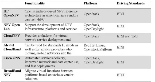
The following table summarizes some of the industry projects on NFV up to this point:
Table 2.2 Industry NFV projects
HP OpenNFV NFVOpen Lab CloudNFV Alea tel CloudBand Cisco ONS BroadBand NFV Functionality
Open standards-based NFV reference architecture in which carriers v endors can test v EPC
Support the developrnent ofNFV infrastructure, platforrns and services Provides a platform for virtual network service deployrnent and Can be used for standards IT needs as well as for service providers who rnoving mobile networks into the Autornated services delivery,
irnproved network and data center use, and fast deployments
Migrate virtual functions between platforrns based on various vendor solutions Platform OpenStack OpenStack, Op enD a y light OpenStack Red Hat Linux, Openstack Platforrn OpenStack, OpenDaylight Driving Standards ET SI ET SI ET SI and TMF ETSI ETSI ETSI
25
CHAPTER3
VIRTUAL MOBILE SIP PROXY INTEGRATION
3.1 Virtual Network Functions Concept in MNO
A network function (NF) is a functional block within a network infrastructure which has well-defined external interfaces and well-defined functional behaviorError! Reference source not found. [33] . A virtual NF is the implementation of the NF on the virtual resources such as a virtual machine (VM). A single virtual NF may be composed of multiple internai components, and hence it could be deployed over multiple VMs. Whereas, each VM hosts a single component of the virtual NF [32]. In the case of NFV, the NFs that make up the service are virtualized and deployed on virtual resources such as a VM. However, in the perspective of the us ers, the services whether based on functions running on a dedicated equipment or on VMs should have the sarne performance. The number, type and ordering of virtual NFs for each service are determined by the service's functional and behavioral specification. Therefore, the behavior of the service is dependent on the constituent virtual NFs Error! Reference source not found.[32].
In this chapter, a solution to resolve the scalability issue in MNOs is proposed. The solution uses the NFV concept to make up the virtualized call management NF in MNOs. TeleFinity IP PBX, which serves as SIP proxy, is the virtualized software solution that is responsible for controlling the call management function in MNO and manage us ers SIP calls' quality. The main benefits to virtualize the SIP proxy are the
programmability, minimal operation cost , unified management, routing, efficient Joad balancing, and optimized management of server resources (including CPU and memory).
Next section presents an overv1ew about the SIP proxy software, its benefits and modules which are used as a part in the proposed solution in the thesis.
3.2 What is SIP Proxy
SIP proxy, in telecommunication, is one of the main components of an IP PBX that is used by SIP to perform many of the cali set-up functions. As described in RFC3621 standard ,SIP makes use of elements, called proxy servers (SIP proxy) to route requests to the user's current location, authenticate and authorize users for the services, implement provider call-routing poli ci es, and provide features to users.
Within the SIP networks, the SIP proxy actually manages the setup of calls between SIP deviees including the controlling of cali routing and it also performs necessary functions such as registration, authorization, network access control and in sorne cases it also handles network security.
TeleFinity IP PBX is used as SIP proxy server within the solution proposed in this thesis because of its key benefits described in the subsection 3.3.1.
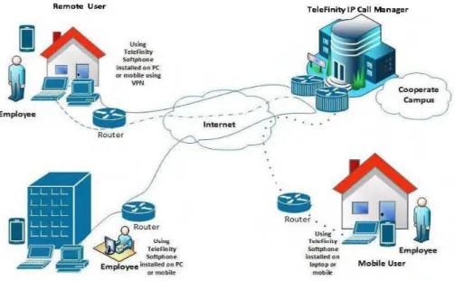
3.3 TeleFinity IP PBX Overview
TeleFinity IP PBX is a complete telephony software solution that provides telephone calls over IP data networks. It boasts robust PBX features, high reliability and scalability, and multi-protocol support. It is an intelligent IP Cali Manager solution
27
that provides contextual, continuous, and high capability journeys for end users [34][34]. It can be also connected to traditional PSTN lines, El lines, Q-SIG lines, and GSM lines via an optional gateway.
TeleFinity IP PBX has open platforrn architecture which is designed to handle a very
high load of calls with maximum performance using minimum hardware requirements. The TeleFinity IP PBX platforrn is built on standard protocol components and operating systems providing J:v1Nü with flexible easy-to-use interface. Its architecture is easy to customize and integrate with other systems. TeleFinity IP PBX Developrnent Kit (SDK) provides developers and system integrators with an option to integrate with any mobile telecommmication system. It enables MNO to route and monitor calls, make robust audio calls upon pre-defined flexible call flow designer and generate advanced statistical reports. Below figure shows typical architecture for TeleFinity IP PBX.
Remote User
Emplo yee
Home Office Agent
Using Telefinity Softptlone in-stalted on PC or mobile using VPN
3.3.1 TeleFinity IP PBX Benefits
The following points present the key benefits of TeleFinity IP PBX solution that make it the best choice to serve the SIP proxy role in the proposed solution:
• It is IP Call Manage Solution that operates under SIP standards. • Integrates with any telephony environment (2G, 3G,4G)
• Can handle up to 2,000 concurrent calls on single platform • It can be supported and activated on any mobile deviee. • No need for SIM swaps or on-deviee applications. • High quality services
• Much easier to install & configure than a proprietary phone system, and easier to manage because of web/GUI based configuration interface.
• Significant cost savings using VoiP providers. • Eliminate vendor lock in.
• Scalable Solution.
• Works efficiently in VM environment.
• Allow hot-desking & roaming (Mobile Extensions). • Better phone usability: SIP phones are easier to use.
• Use existing network infrastructure without additional hardware.
3.4 TeleFinity IP PBX Modules
This section lists the modules supported by TeleFinity IP PBX solution. These modules present several NFs in MNO such as call accounting function, call monitor function, IVR function, sending fax function, etc. Moreover, these modules can be installed on VMs and used by the operators to offer new web services to their clients.
29
These web services can be managed by the end user himself using specifie portal application installed on their mobile deviees.
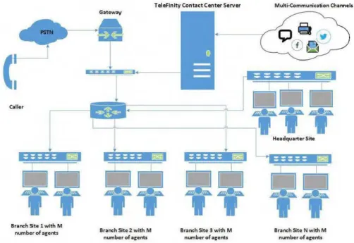
3.4.1 Call Center Module
Contact Center is SIP based solution that routes calls to queues, analyze and generate advanced statistical reports that helps in optimizing the contact center performance. Contact Center is a cutting-edge PC based solution with open platform architecture. It is robust, reliable, scalable, and affordable contact center solution appropriate for small-scale to large operators.
Contact Center module runs up to 12,000 seats with unlimited number of agents. It can be expanded up to unlimited number of seats, making Contact Center extremely scalable, meeting MNO needs.
Caller
Branch Site 1 with M number of acents
Gateway
Branch Site 2 with M number of ac ents
T elef inity Contact Cen ter Server
Branch Site 3 with M number of a cents
Multi·Communicati on Channels
::: ::: ::: ::: ::: 1:1!!:1
Branch Site N with M number of acents
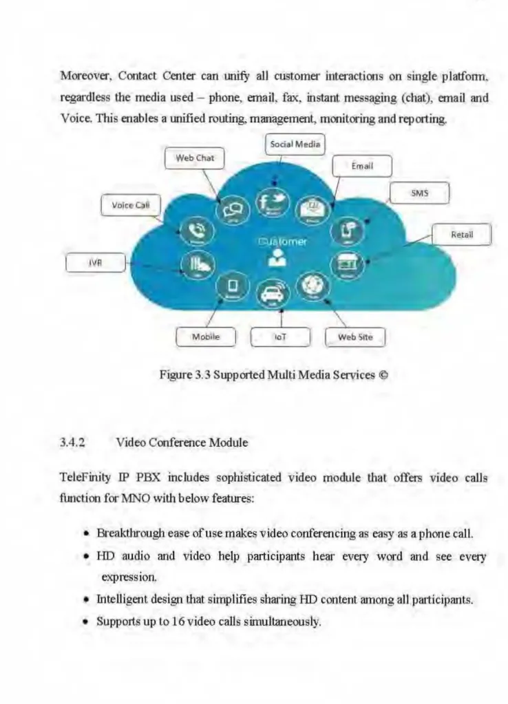
Moreover, Contact Center can
l.ll1ifY
ali customer interactions on single platform. regardless the media us ed - phone, email, fax, instant messaging (chat), email and Voice. This enables a unified routing, management, monitoring and reporting.IV Il
Figure 3.3 Supported MultiMedia Services @
3.4.2 V ideo Conference Module
TeleFinity IP PBX includes sophisticated video module that offers video calls function for l\1NO with below features:
• Breakthrough ease of use makes video conferencing as easy as a phone ca11. • HD audio and video help participants hear every word and see every
expression.
• Intelligent design that simplifies sharing HD content among ali patticipants. • Supports up to 16 video calls simultaneously.
31
3.4.3 Interactive Voice Response (IVR) Module
IVR module is a powerful Interactive Voice Response (IVR) Engine and Management Module. lt is designed to otier very sophisticated features with a user configurable interface that uniquely provides IVR designer tool in a flow chart design. The IVR module can replace digit-intensive dual tone multi-frequency (DT11F) "Touch-tone" IVR interfaces with speech-enabled service.
Users can develop their own IVR applications using powerful and familiar scripting tools such as visual basic (VB) Script. The user can take full control of the call flow using the embedded object, which provides all the telephony functionality necessary to develop IVR applications. The user can use the existing capabilities of VB Script to connect to other system's database and hosts. Scripting Language supported by IVR module is VXML with .wav supported audio type.
t~ F~e Script Window Help . - - - -"Il
El···&) T elephony Contrais
:4~ Pl4ile : .... q:~ RecordFile i·---~ GetOigits i----(} Pla.YDate-Time i----~ PlayNumber i----~ PlayDiscreteNumber .. $ .. Pla9M oney i···-,,~~ PlayDuration i···1tJ~ PlayString : .. ft. Pla.YPrompt :----hng Changelanguage !---- IJBS VBScript ; ____ ~&; T ransferCall ~----~ Oatabase i···· ~ VoiceMail "· 1b Hangup : ····-~ Container ~---~ Internet !-··· "'!~ XMLObject L. .. J..L,.. SendEmail ~ NewCall 1
l
lr---r-
~ ---11
~BSChecliN"orkliœ 1 1 1 ~ _:]PIN"Timo J f:.=Jowrime .J, ~)~LeaveVoîceMsg [1
Jfb® l eav.eV oîceMessag j . 1[Wl
Get0igits12 1 1 ~BSCheckTickePN-1 ~:JQuestioner 1 .J, ~p l eaveV oiceMessageVI1
1[Wl
Get0igits211
Jlf~PiayVoiceMsg ~ Ill
·-fS2J...,sendEmaîiVIP 1 fSZJ.,. SondEmaüS 1 1 , . - - - - " 1-i~ H angup7 1§ .4.4 Oall R:ec&r~g M~du1e
Gall t•ec:crding. tttl>dula
pr~videa .cqtnprehertshr:e.t:tL1.1lti·chaMel
recordirtg .capal.lillti~> th!!thelp·
!liNO ·PPtimizittgthe c!lst<>mer
caf~,<!ge!lt petfiéirtna!l.ce·, and r:eg!llawy
C()ln}iliali:Ct'.
r
1
1
1 - - - - 1
~~-=--~logfinity f>a~ve Re<'ording Met!"'
C:;i!l acc:ounting module tracks in comjng and ot)tgoing phom calls in real tirne:
Addftionally;,
it
identift:e> telec:cm exp etl.ses, ftàud, errt ergenty calls, :md W$rJtoonditi11ns. It afsq provides eagy .to reatl c.a!l vol urne and t'funk usage .grapbs. that help
33
.lm ... _
f ••• t• " • l u' "'> • •~• l4 ~t"~~' " lh"'" ' + 1
[:;
- - -- - -
- - - . ,_
_,Figure 3.6 Gall Accounting Module [14]
3.4.6
Fax Module
The Fax Server Application solution is ùnplemented using tlre fax over IP (FOIP)
technology integrated with IP Cali Managermadule.
Fax over IP functionality enables sending faxes over the fax line and the Intemd at
the samè tùne.
Itcan be integrated with tlre existing lP infrastructure, such as
IP-enahled PBXs.
U sing the SMTP protocol, the users will be able
Iosend and receive faxes ahd text
messages directly from their email account. To achieve this, the :fux module must be
integrated with the e-mail server. Wh en the fàx is received, it will be sent to the agent
email account with fax. message attachments (TIFF, RTF, etc .. . ),.As weil, the
message can be savf;d easily and the agent has the ability to send. reply and receive
faxes easily. The Fax message is.stored in themailboxes o!each uset
Fax Gateway
TeleFinity Contact Center
1
=====
~Fa.x Machine
•
"
End UserAgent
Figure 3. 7 Fax Module ©
3.5 Mobile SIP Proxy Integration Approach
The proposed solution offers a hosted SIP Proxy application installed on VM within the MNO platform and it is integrated with the existing telecommunication entities using a SIP trunk. Multiple SIP proxy solutions can be deployed on multiple VMs to allow handling a greater number of subscribers. Each SIP proxy is installed on VM with high resources specifications i.e. CPU is Intel Xeon or better and memory size is 64GB or higher, and it can handle up to 2,000 concurrent calls on a single platform.
In this approach, the mobile terminal is registered as VoiP extension to the SIP proxy via mobile software application installed on the user deviee. Each mobile terminal
35
can experience the same feature set as any mobile phone deviee connected to a mobile operator. The mobile terminal routes the calls via a packet-switched PS data connection of mobile operator as VoiP calls using IP connections. The mobile software application updates a presence status of the mobile phone to the SIP proxy. As well, it records the dialing user calls to a predefined number which is routed to the SIP proxy's dial-in service, and sends the user dialing to the proxy using DTMF (Dia! Tone Multi-Frequency Signaling) signais.
As shown in figure 3.8, the proposed solution ,which is bordered with dotted blue line) is applicable to any user terminal e.g. a mobile or a wireless user terminal, such as a mobile phone , a user communication terminal with wire, a persona! digital assistant (PDA), a game console, an e-reading deviee, a tablet, a smart phone, a persona! computer (PC), a laptop, or a desktop computer .As well, this proposed solution can be integrated with any communications system or any combinations of
different communications systems that support 2G, 3G, 4G and/or SG systems using
the SIP trunk without the interfering of their existing infrastructure. The communication systems may be a fixed communications system ( e.g. landline networks) or a wireless communications system ( e.g. mobile phone networks) or a communications system utilizing both fixed networks and wireless networks.
1 Telephony 1 servers host multiple 1 VMs 1 1 1 1 Application Server/ 1 Gate l 1 1 1 1 1 1 MNO Network:-....,b~~~b--...;...-"""\
__ ""' _1
/ CAMEU ISUP/MAP '~-~---~~~
MNO Network Components( GMSC, IN,HSS, .. )
MNO Users
Figure 3.8 Proposed Solution Diagram ©
CA MEL: Customized Applications for Mobile networks Enhanced Log1c ISUP:ISDN User Part MAP: Mobile Application Part GMSC: Gateway Mobile Switching Center IN: Intelligent Network
3.6 Proposed Architecture
3.6.1 Solution Design
E•istinc Mobile
Ope rotor U sers A-Interface Mobile Operator Core Network
EJ
D
[ ]
BSS SIPTrunk SIP Traffic RTP Traffic SIPProxyVM \ '-. lftt. .______--,---' \ -fi 1 ~ ' WebPortoiVM~
\
L---~~
SIP Signaling\
~
\1
. StoroceVM1
l i~
TCP'-Figure 3.9 Proposed Solution Architectural Design©
37
Mobile Application
In figure 3.9, high-level solution architectural design is presented. As shown, the existing mobile users can access the communications network via an access network, e.g. via a base station subsystem (BSS) or a radio network subsystem. The core network element in 1ANO comprises a GMSC element (Gateway Mobile Switching Center element). It is an ex change element controlling the area, in which the mobile subscriber is presently located. As well, it can interrogate the routing of mobile terminating calls. GMS C can send notifications of registration and de-registration events of a mobile subscriber to an SCP (Service Control Point) which is a node that
directs services m the intelligent network (IN). GMSC can request routing instructions from SCP on how to route an originating cali or a terminating cali of a user. SCP can th en return a pre-defined prefix which is added before the destination number with which the cali can be routed. GMSC can then route or direct the cali to a SIP proxy VM. The purpose of using SCP in MNOs is to receive notifications of attach and detach procedures of the subscriber's IMSI (International Mobile Subscriber Identity Code) number and of location update events from GMSC. At !east partly based on this information, SCP can determine whether the subscriber is currently registered to the network or not. SCP further de livers this information to the Application Service VM.
The Application Service (AS) VM in the above system architecture is responsible for controlling and managing the service that receives the registration and/or de-registration notifications from the SCP. When AS VM receives a new SIP session from the GMSC, its service recognizes the subscriber from the SIP signaling message, then it be gins a new SIP session to the SIP proxy as an SIP extension of the subscriber. The same thing is done for the traffic in the opposite side, when the service on AS VM receives a SIP session from the SIP proxy, it recognizes the recipient from the SIP signaling, then it begins a new session with GMSC to the mobile deviee, combining the media of the incoming and outgoing sessions.
SIP proxy VM in the above system architecture is responsible for controlling SIP extensions registration and managing the switching of their calls. SIP proxy can receive the registration, and authenticate the user and deliver the traffic according to its configuration. The SIP proxy VM is interconnected with storage VM via TCP connection which is responsible for data processing for client calls history, calls records and clients status and save it in a predefined database schema on SQL Database server. As weil, the SIP proxy VM is interconnected with web portal VM via HTTP connection which identifies the incoming requests from web clients. The
39
main components contained in a web portal VM are the virtual directories which receive the inbound HTTP requests and process them.
3.6.2 VM Specifications
111is section presents the VM specifications needed to deploy the proposed solution within the MNO platform. Three VMs are required with the below minimum specifications:
Table 3.1 Minimum VMs Specifications
Minimum VMs Specifications
Telephony VM DB & Portal VM Application Server VM
CPU Intel Xeon ES-2699
v4 RAM 64GB HDD Storage 1 TB Data base
os
Windows Server R2 2008 64-bits SP1 A- Telephony VMIntel Xeon ES-2699 v4 64GB
1 TB SQL Server R2 2008 Standard Edition 64-bits Windows Server R2 2008
64-bits SP1
Qaud Core CPU 8GB 500GB
Ubuntu 14.04.3 LIS server
TI1e SIP proxy solution is implemented on the Telephony VM. TI1e nummum technical specifications of the Telephony VM required to serve up to 12,000 subscribers and 2,000 concurrent calls/VM server are given in table 3.1.
![Figure 1.1 LTE Network Entities [2]](https://thumb-eu.123doks.com/thumbv2/123doknet/7642898.236736/15.918.226.686.600.986/figure-lte-network-entities.webp)
![Figure 2.1 Traditional network layers versus logicallayers in a SDNNetwork [30]](https://thumb-eu.123doks.com/thumbv2/123doknet/7642898.236736/29.918.186.782.260.465/figure-traditional-network-layers-versus-logicallayers-in-sdnnetwork.webp)
![Figure 2.2 fudicative SDN architecture and mapping to N.FV [30]](https://thumb-eu.123doks.com/thumbv2/123doknet/7642898.236736/30.918.65.845.92.1093/figure-fudicative-sdn-architecture-mapping-n-fv.webp)
![Figure 23 H'igh Leve.1 NFV Domain s. [24][32)](https://thumb-eu.123doks.com/thumbv2/123doknet/7642898.236736/31.918.76.823.65.1114/figure-h-igh-leve-nfv-domain-s.webp)
![Figure 2.4.End to end service Graph r~presentatinn (32]](https://thumb-eu.123doks.com/thumbv2/123doknet/7642898.236736/32.918.75.833.105.845/figure-end-end-service-graph-r-presentatinn.webp)
![Figure 2.5 Architectu.ral -descript:ion of NFV [ 32]](https://thumb-eu.123doks.com/thumbv2/123doknet/7642898.236736/33.920.81.820.134.1063/figure-architectu-ral-descript-ion-nfv.webp)